esp wiring SUZUKI SWIFT 2006 2.G Service Workshop Manual
[x] Cancel search | Manufacturer: SUZUKI, Model Year: 2006, Model line: SWIFT, Model: SUZUKI SWIFT 2006 2.GPages: 1496, PDF Size: 34.44 MB
Page 19 of 1496
Downloaded from www.Manualslib.com manuals search engine Precautions: 00-14
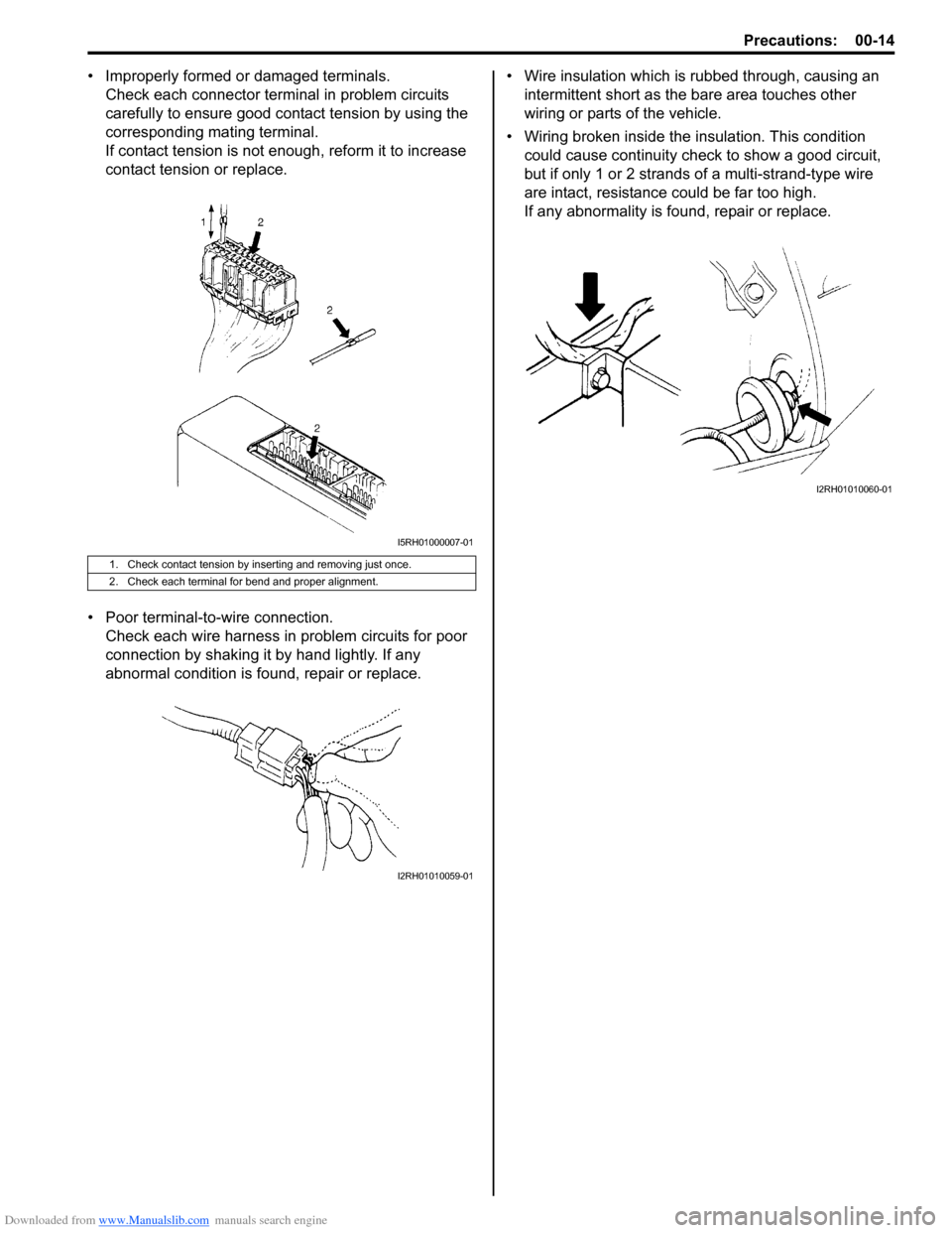
• Improperly formed or damaged terminals.Check each connector terminal in problem circuits
carefully to ensure good contact tension by using the
corresponding mating terminal.
If contact tension is not enough, reform it to increase
contact tension or replace.
• Poor terminal-to -wire connection.
Check each wire harness in problem circuits for poor
connection by shaking it by hand lightly. If any
abnormal condition is found, repair or replace. • Wire insulation which is rubbed through, causing an
intermittent short as the bare area touches other
wiring or parts of the vehicle.
• Wiring broken inside the insulation. This condition
could cause continuity check to show a good circuit,
but if only 1 or 2 strands of a multi-strand-type wire
are intact, resistance could be far too high.
If any abnormality is found, repair or replace.
1. Check contact tension by inserting and removing just once.
2. Check each terminal for bend and proper alignment.
I5RH01000007-01
I2RH01010059-01
I2RH01010060-01
Page 97 of 1496
Downloaded from www.Manualslib.com manuals search engine Engine General Information and Diagnosis: 1A-47
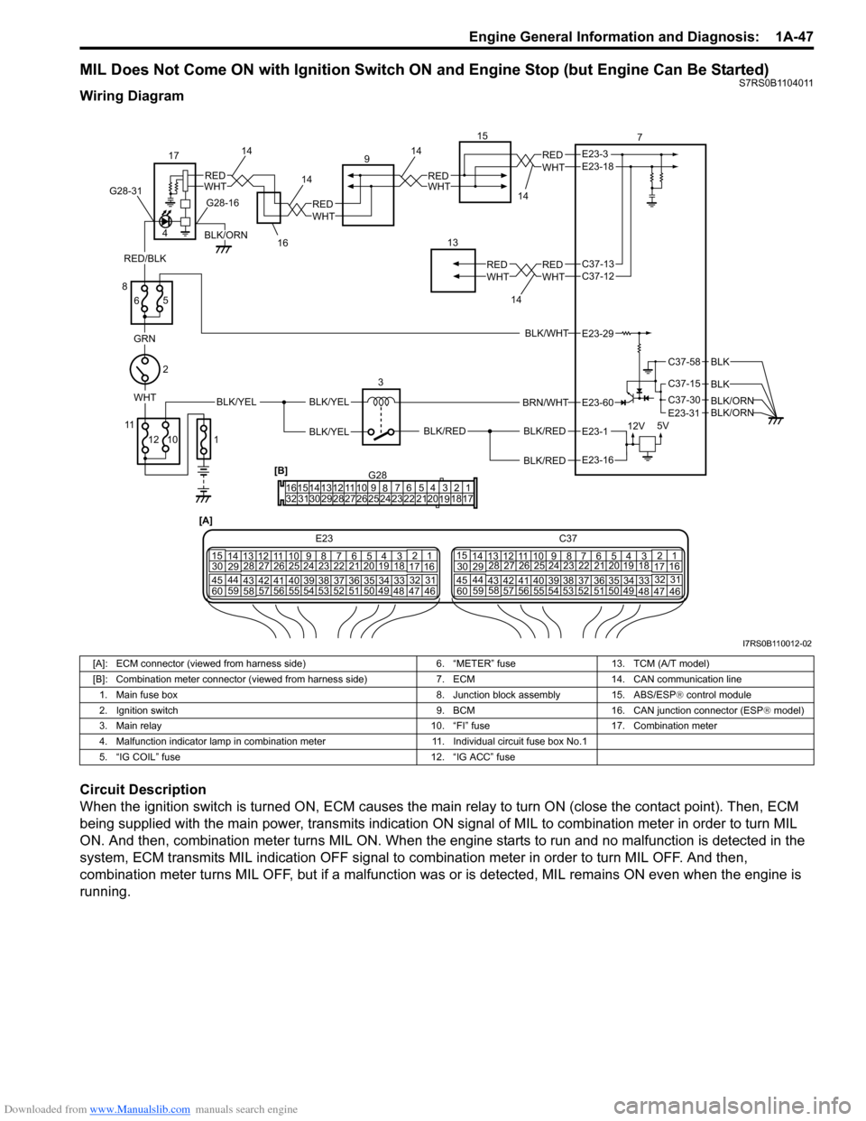
MIL Does Not Come ON with Ignition Switch ON and Engine Stop (but Engine Can Be Started)S7RS0B1104011
Wiring Diagram
Circuit Description
When the ignition switch is turned ON, ECM causes the main relay to turn ON (close the contact point). Then, ECM
being supplied with the main power, transmits indication ON si gnal of MIL to combination meter in order to turn MIL
ON. And then, combination meter turns MIL ON. When the engine starts to run and no malfunction is detected in the
system, ECM transmits MIL indication OFF signal to combination meter in order to turn MIL OFF. And then,
combination meter turns MIL OFF, but if a malfunction was or is detected, MIL remains ON even when the engine is
running.
G281234567
8
910
11
1213141516
1718
19
20
212223242526272829303132
[B]
[A]
E23 C37
34
1819
567
10
11
17
20
47 46
495051
2122
52 16
25 9
24
14
29
5557 54 53
59
60 58 2
262728
15
30
56 4832 31
34353637
4042 39 38
44
45 43 41 331
1213
238
34
1819
567
10
11
17
20
47 46
495051
2122
52 16
25 9
24
14
29
5557 54 53
59
60 58 2
262728
15
30
56 4832 31
34353637
4042 39 38
44
45 43 41 331
12
13
238
BLK/WHT
BLK/RED
BLK/RED
BRN/WHT
BLK/REDWHTBLK/YEL
GRN
12V 5V
2
3
8
6 7
E23-29
E23-3
E23-1
E23-60
E23-18
E23-16
1014
14
12
11
RED/BLK
C37-58
C37-15
C37-30
BLK
E23-31
BLK
BLK/ORNBLK/ORN
4
WHTREDWHTRED
BLK/ORN
G28-16
15
13
14
1414
G28-31
BLK/YEL
BLK/YEL
WHTRED
WHTRED
WHTREDC37-13 C37-12
WHTRED
9
17
5 1 16
I7RS0B110012-02
[A]: ECM connector (viewed from harness side)
6. “METER” fuse13. TCM (A/T model)
[B]: Combination meter connector (viewed from harness side) 7. ECM14. CAN communication line
1. Main fuse box 8. Junction block assembly15. ABS/ESP® control module
2. Ignition switch 9. BCM16. CAN junction connector (ESP® model)
3. Main relay 10. “FI” fuse17. Combination meter
4. Malfunction indicator lamp in combination meter 11. Individual circuit fuse box No.1
5. “IG COIL” fuse 12. “IG ACC” fuse
Page 178 of 1496
Downloaded from www.Manualslib.com manuals search engine 1A-128 Engine General Information and Diagnosis:
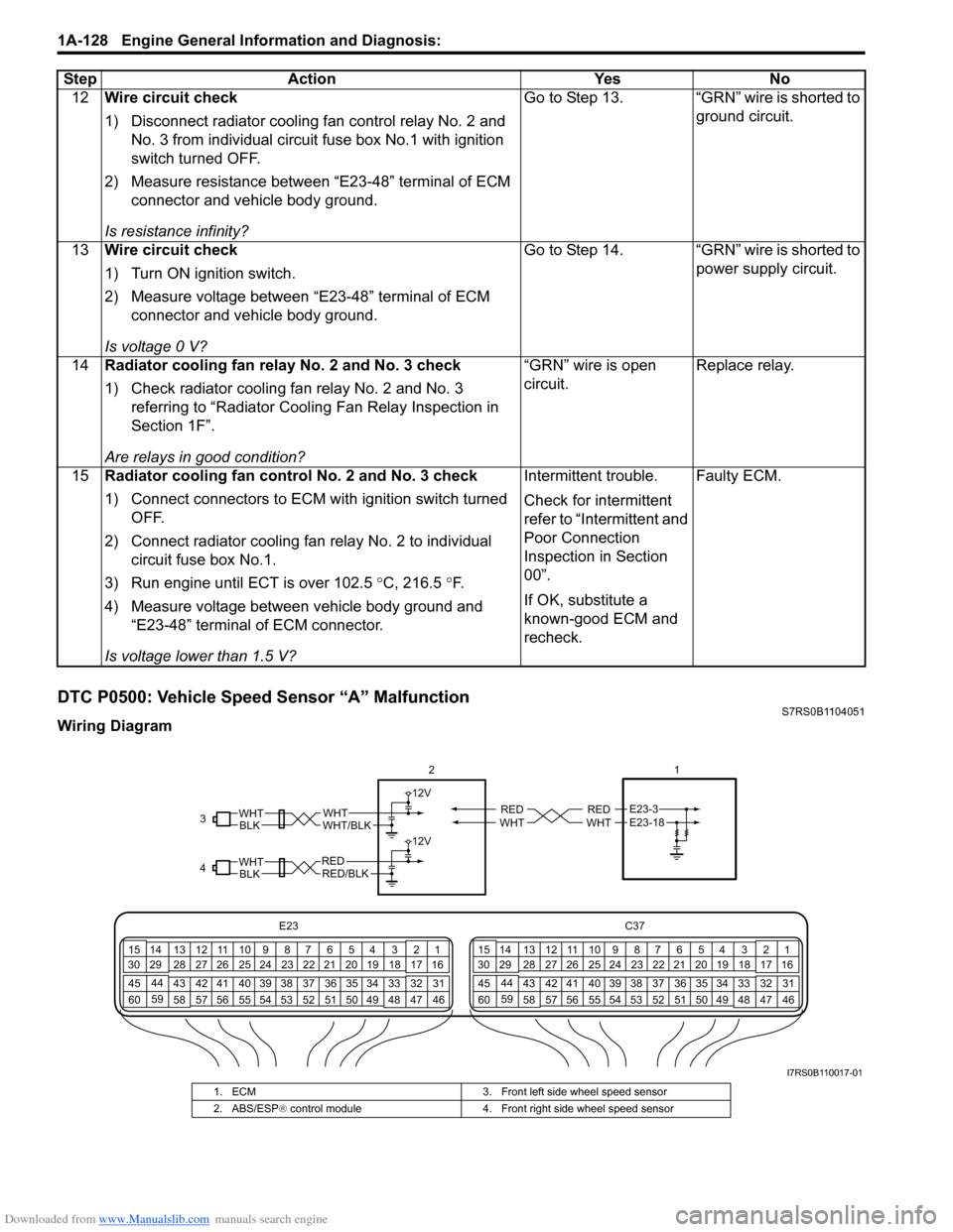
DTC P0500: Vehicle Speed Sensor “A” MalfunctionS7RS0B1104051
Wiring Diagram12
Wire circuit check
1) Disconnect radiator cooling fan control relay No. 2 and
No. 3 from individual circuit fuse box No.1 with ignition
switch turned OFF.
2) Measure resistance between “E23-48” terminal of ECM connector and vehicle body ground.
Is resistance infinity? Go to Step 13. “GRN” wire is shorted to
ground circuit.
13 Wire circuit check
1) Turn ON ignition switch.
2) Measure voltage between “E23-48” terminal of ECM
connector and vehicle body ground.
Is voltage 0 V? Go to Step 14. “GRN” wire is shorted to
power supply circuit.
14 Radiator cooling fan relay No. 2 and No. 3 check
1) Check radiator cooling fan relay No. 2 and No. 3
referring to “Radiator Coolin g Fan Relay Inspection in
Section 1F”.
Are relays in good condition? “GRN” wire is open
circuit.
Replace relay.
15 Radiator cooling fan control No. 2 and No. 3 check
1) Connect connectors to ECM with ignition switch turned
OFF.
2) Connect radiator cooling fan relay No. 2 to individual circuit fuse box No.1.
3) Run engine until ECT is over 102.5 °C, 216.5 °F.
4) Measure voltage between vehicle body ground and “E23-48” terminal of ECM connector.
Is voltage lower than 1.5 V? Intermittent trouble.
Check for intermittent
refer to “Intermittent and
Poor Connection
Inspection in Section
00”.
If OK, substitute a
known-good ECM and
recheck.
Faulty ECM.
Step Action Yes No
E23
C37
34
1819
567
10
11
17
20
47 46
495051
2122
52 16
25 9
24
14
29
55
57 54 53
59
60 58 2
262728
15
30
56 4832 31
34353637
40
42 39 38
44
45 43 41 331
1213
238
34
1819
567
10
11
17
20
47 46
495051
2122
52 16
25 9
24
14
29
55
57 54 53
59
60 58 2
262728
15
30
56 4832 31
34353637
40
42 39 38
44
45 43 41 331
1213
238
E23-3E23-18REDWHTREDWHTWHT/BLKWHTBLKWHT
BLKWHTREDRED/BLK
12V
12V
3
4 21
I7RS0B110017-01
1. ECM
3. Front left side wheel speed sensor
2. ABS/ESP® control module 4. Front right side wheel speed sensor
Page 195 of 1496
Downloaded from www.Manualslib.com manuals search engine Engine General Information and Diagnosis: 1A-145
DTC Troubleshooting
NOTE
• When measuring circuit voltage, resistance and/or pulse signal at ECM connector, connect the
special tool to ECM and/or the ECM connectors re ferring to “Inspection of ECM and Its Circuits”.
• Upon completion of inspection and repair work, perform “DTC Confirmation Procedure” and confirm that the trouble has been corrected.
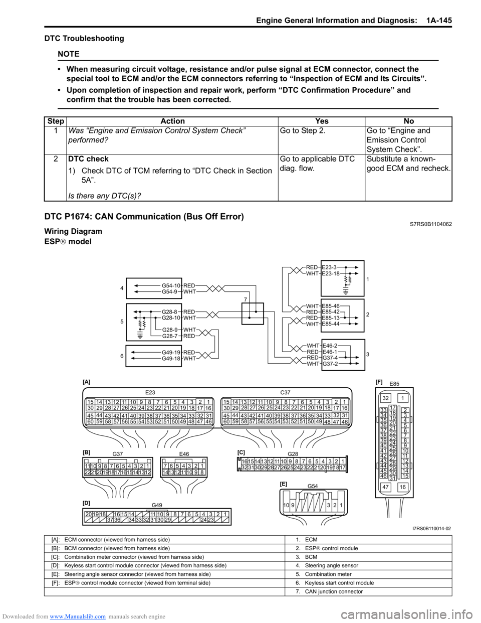
DTC P1674: CAN Communication (Bus Off Error)S7RS0B1104062
Wiring Diagram
ESP ® model
Step Action Yes No
1 Was “Engine and Emission Control System Check”
performed? Go to Step 2. Go to “Engine and
Emission Control
System Check”.
2 DTC check
1) Check DTC of TCM referring to “DTC Check in Section
5A”.
Is there any DTC(s)? Go to applicable DTC
diag. flow.
Substitute a known-
good ECM and recheck.
[F]
E85
161
15
2
3
4
5
6
7
8
9
10
11
12
13
14
17
18
19
20
21
22
23
24
25
26
27
28
29
30
31
3233
34
35
36
37
38
39
40
41
42
43
44
45
46
47
[D] 12345678910
11
141516
36 34 33 32 31 30 29 24 23
37
181920
G49
[A]
E23
C37
34
1819
567
10
11
17
20
47 46
495051
2122
52 16
25 9
24
14
29
5557 54 53
59
60 58 2
262728
15
30
56 4832 31
34353637
4042 39 38
44
45 43 41 331
1213
238
34
1819
567
10
11
17
20
47 46
495051
2122
52 16
25 9
24
14
29
5557 54 53
59
60 58 2
262728
15
30
56 4832 31
34353637
4042 39 38
44
45 43 41 331
12
13
238
[C]G28
1234567
8
910
11
1213141516
1718
19
20
212223242526272829303132
[E] G54
109 321
[B]
G37E46
1234567 1234567
8910
11
8910
11
121314 121314
1516171819202122
4
6 1
2
3
REDWHT
REDWHT
REDWHT
REDWHT
REDWHT
E23-3E23-18
E85-42E85-46
E85-13E85-44
E46-1E46-2
G37-4G37-2
REDWHT
REDWHTG49-19G49-18
5
7
WHTG54-9REDG54-10
G28-8G28-10
G28-7REDG28-9WHT
I7RS0B110014-02
[A]: ECM connector (viewed from harness side)
1. ECM
[B]: BCM connector (viewed from harness side) 2. ESP® control module
[C]: Combination meter connector (viewed from harness side) 3. BCM
[D]: Keyless start control module connector (vie wed from harness side) 4. Steering angle sensor
[E]: Steering angle sensor connector (viewed from harness side) 5. Combination meter
[F]: ESP ® control module connector (viewed from terminal side) 6. Keyless start control module
7. CAN junction connector
Page 199 of 1496
Downloaded from www.Manualslib.com manuals search engine Engine General Information and Diagnosis: 1A-149
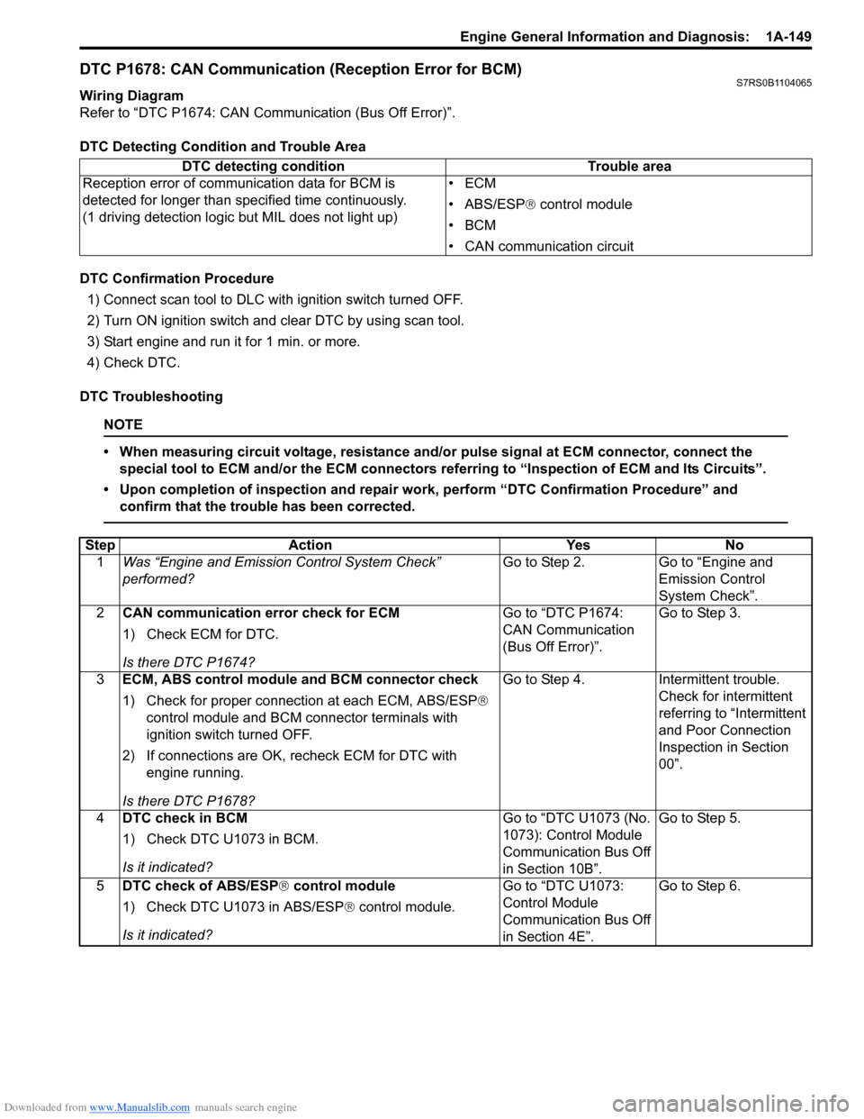
DTC P1678: CAN Communication (Reception Error for BCM)S7RS0B1104065
Wiring Diagram
Refer to “DTC P1674: CAN Communication (Bus Off Error)”.
DTC Detecting Condition and Trouble Area
DTC Confirmation Procedure1) Connect scan tool to DLC with ignition switch turned OFF.
2) Turn ON ignition switch and clear DTC by using scan tool.
3) Start engine and run it for 1 min. or more.
4) Check DTC.
DTC Troubleshooting
NOTE
• When measuring circuit voltage, resistance and/ or pulse signal at ECM connector, connect the
special tool to ECM and/or the ECM connectors re ferring to “Inspection of ECM and Its Circuits”.
• Upon completion of inspection and repair work, perform “DTC Confirmation Procedure” and confirm that the trouble has been corrected.
DTC detecting condition Trouble area
Reception error of communication data for BCM is
detected for longer than specified time continuously.
(1 driving detection logic but MIL does not light up) •ECM
• ABS/ESP®
control module
•BCM
• CAN communication circuit
Step Action YesNo
1 Was “Engine and Emission Control System Check”
performed? Go to Step 2.
Go to “Engine and
Emission Control
System Check”.
2 CAN communication error check for ECM
1) Check ECM for DTC.
Is there DTC P1674? Go to “DTC P1674:
CAN Communication
(Bus Off Error)”.
Go to Step 3.
3 ECM, ABS control module and BCM connector check
1) Check for proper connecti on at each ECM, ABS/ESP®
control module and BCM connector terminals with
ignition switch turned OFF.
2) If connections are OK, recheck ECM for DTC with engine running.
Is there DTC P1678? Go to Step 4.
Intermittent trouble.
Check for intermittent
referring to “Intermittent
and Poor Connection
Inspection in Section
00”.
4 DTC check in BCM
1) Check DTC U1073 in BCM.
Is it indicated? Go to “DTC U1073 (No.
1073): Control Module
Communication Bus Off
in Section 10B”.Go to Step 5.
5 DTC check of ABS/ESP ® control module
1) Check DTC U1073 in ABS/ESP ® control module.
Is it indicated? Go to “DTC U1073:
Control Module
Communication Bus Off
in Section 4E”.Go to Step 6.
Page 200 of 1496
Downloaded from www.Manualslib.com manuals search engine 1A-150 Engine General Information and Diagnosis:
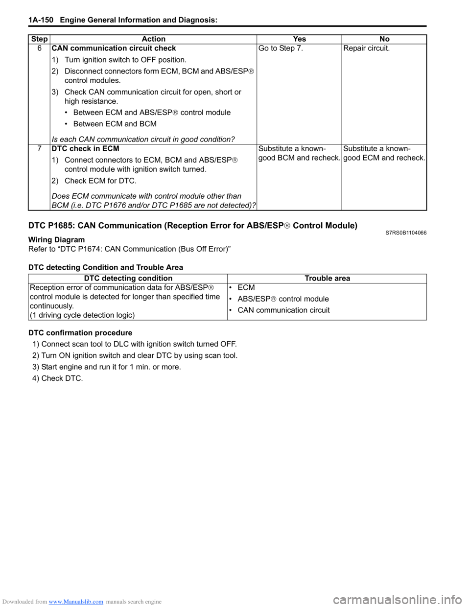
DTC P1685: CAN Communication (Reception Error for ABS/ESP® Control Module)S7RS0B1104066
Wiring Diagram
Refer to “DTC P1674: CAN Communication (Bus Off Error)”
DTC detecting Condition and Trouble Area
DTC confirmation procedure
1) Connect scan tool to DLC with ignition switch turned OFF.
2) Turn ON ignition switch and clear DTC by using scan tool.
3) Start engine and run it for 1 min. or more.
4) Check DTC. 6
CAN communication circuit check
1) Turn ignition switch to OFF position.
2) Disconnect connectors fo rm ECM, BCM and ABS/ESP®
control modules.
3) Check CAN communication circuit for open, short or high resistance.
• Between ECM and ABS/ESP ® control module
• Between ECM and BCM
Is each CAN communication circuit in good condition? Go to Step 7. Repair circuit.
7 DTC check in ECM
1) Connect connectors to ECM, BCM and ABS/ESP ®
control module with ignition switch turned.
2) Check ECM for DTC.
Does ECM communicate with control module other than
BCM (i.e. DTC P1676 and/or DTC P1685 are not detected)? Substitute a known-
good BCM and recheck.
Substitute a known-
good ECM and recheck.
Step
Action YesNo
DTC detecting condition Trouble area
Reception error of communication data for ABS/ESP ®
control module is detected for longer than specified time
continuously.
(1 driving cycle detection logic) •ECM
• ABS/ESP®
control module
• CAN communication circuit
Page 259 of 1496
Downloaded from www.Manualslib.com manuals search engine Engine General Information and Diagnosis: 1A-209
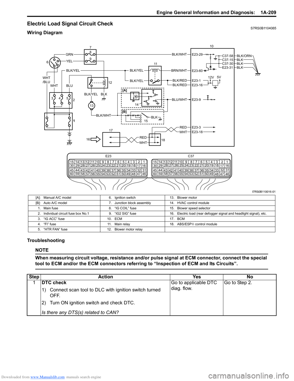
Electric Load Signal Circuit CheckS7RS0B1104085
Wiring Diagram
Troubleshooting
NOTE
When measuring circuit voltage, resistance and/or pulse signal at ECM connector, connect the special
tool to ECM and/or the ECM connectors referri ng to “Inspection of ECM and Its Circuits”.
BLK/WHT
BLK/RED
WHT
BRN/WHT
12V5V
11
BLK/YELBLK/YEL
BLK/YEL
BLKBLKBLK
BLK/ORN
10
18
17
BLU/WHT
15
WHTRED
43
YEL
5
13
BLK/WHT
BLKBLK/YEL
GRN
WHT
/BLU
BLU
16
2
6
7
12
8
9
BLK
WHT
RED
E23-29
E23-60
E23-1E23-16
E23-9
E23-3E23-18
C37-58C37-15
E23-31C37-30
BLK/RED
[A]
[B]
E23 C37
34
1819
567
10
11
17
20
47 46
495051
2122
52 16
25 9
24
14
29
5557 54 53
59
60 58 2
262728
15
30
56 4832 31
34353637
4042 39 38
44
45 43 41 331
1213
238
34
1819
567
10
11
17
20
47 46
495051
2122
52 16
25 9
24
14
29
5557 54 53
59
60 58 2
262728
15
30
56 4832 31
34353637
4042 39 38
44
45 43 41 331
12
13
238
1
14
I7RS0B110016-01
[A]: Manual A/C model
6. Ignition switch13. Blower motor
[B]: Auto A/C model 7. Junction block assembly14. HVAC control module
1. Main fuse 8. “IG COIL” fuse15. Blower speed selector
2. Individual circuit fuse box No.1 9. “IG2 SIG” fuse16. Electric load (rear defogger signal and headlight signal), etc.
3. “IG ACC” fuse 10. ECM17. BCM
4. “FI” fuse 11. Main relay18. ABS/ESP® control module
5. “HTR FAN” fuse 12. Blower motor relay
StepAction YesNo
1 DTC check
1) Connect scan tool to DLC with ignition switch turned
OFF.
2) Turn ON ignition switch and check DTC.
Is there any DTS(s) related to CAN? Go to applicable DTC
diag. flow.
Go to Step 2.
Page 496 of 1496

Downloaded from www.Manualslib.com manuals search engine 4-ii Table of Contents
Repair Instructions ..............................................4D-2Parking Brake Inspection and Adjustment ..........4D-2
Parking Brake Cable Removal and Installation ......................................................... 4D-3
Parking Brake Lever Removal and Installation ....4D-3
Specifications .... ...................................................4D-4
Tightening Torque Specifications ........................4D-4
ABS ........................................... .................4E-1
Precautions........................................................... 4E-1
Precautions in Diagnosing Troubles ................... 4E-1
Precautions in On-Vehicle Service...................... 4E-1
Precautions in Hydraulic Unit Operation Check ................................................................ 4E-1
General Description ............................................. 4E-2 ABS Description .................................................. 4E-2
ABS Hydraulic Unit / Control Module Assembly Description ....................................... 4E-2
CAN Communication System Description........... 4E-3
Schematic and Routing Diagram ........................ 4E-4 ABS Schematic ................................................... 4E-4
ABS Wiring Circuit Diagram ................................ 4E-5
Component Location ........... ................................ 4E-7
ABS Components Location ................................. 4E-7
Front Wheel Speed Sensor Components Location ............................................................ 4E-7
Rear Wheel Speed Sensor Components Location ............................................................ 4E-8
Diagnostic Information and Procedures ............ 4E-8 ABS Check .......................................................... 4E-8
ABS Warning Light Check................................. 4E-10
EBD Warning Light (Brake Warning Light) Check .............................................................. 4E-10
DTC Check........................................................ 4E-11
DTC Table ......................................................... 4E-11
DTC Clearance ................................................. 4E-12
Scan Tool Data ................................................. 4E-12
ABS Warning Light Does Not Come ON at Ignition Switch ON .......................................... 4E-13
ABS Warning Light Comes ON Steady ............. 4E-14
EBD Warning Light (Brake Warning Light) Comes ON Steady .......................................... 4E-15
Serial Data Link Circuit Check .......................... 4E-16
DTC C1021, C1022 / C1025, C1026 / C1031, C1032 / C1035, C1036: Right-Front / Left-
Front / Right-Rear / Left-Rear Wheel Speed
Sensor Circuit or Sensor Ring ........................ 4E-18
DTC C1041 / C1045 / C1051 / C1055, DTC C1042 / C1046 / C1052 / C1056: Right-Front
/ Left-Front / Right-Rear / Left-Rear Inlet
Solenoid Circuit, Right-Front / Left-Front /
Right-Rear / Left-Rear Outlet Solenoid
Circuit .............................................................. 4E-20
DTC C1057: Power Source Circuit ................... 4E-21
DTC C1061: ABS Pump Motor and/or Motor Driver Circuit ................................................... 4E-22
DTC C1063: Solenoid Valve Power Supply Driver Circuit ................................................... 4E-23
DTC C1071: ABS Control Module..................... 4E-24 DTC U1073: Control Module Communication
Bus Off ............................................................ 4E-25
DTC U1100: Lost Communication with ECM (Reception Error)............................................. 4E-27
Repair Instructions ............ ................................ 4E-28
ABS Hydraulic Unit Operati on Check................ 4E-28
ABS Hydraulic Unit / Control Module
Assembly Components ...... ............................. 4E-29
ABS Hydraulic Unit / Control Module
Assembly On-Vehicle Inspection .................... 4E-29
ABS Hydraulic Unit / Control Module
Assembly Removal and Inst allation ................ 4E-29
Front / Rear Wheel Speed Sensor On-Vehicle Inspection ........................................................ 4E-31
Front Wheel Speed Sensor Removal and Installation ....................................................... 4E-32
Front Wheel Speed Sensor Inspection ............. 4E-32
Rear Wheel Speed Sensor Removal and Installation ....................................................... 4E-33
Rear Wheel Speed Sensor Inspection .............. 4E-34
Front Wheel Encoder On-Veh icle Inspection .... 4E-34
Front wheel Enco der Removal and
Installation ....................................................... 4E-34
Rear Wheel Encoder On-Veh icle Inspection..... 4E-34
Rear Wheel Encoder Removal and Installation ....................................................... 4E-34
Specifications ..................... ................................ 4E-35
Tightening Torque Specifications ...................... 4E-35
Special Tools and Equipmen t ........................... 4E-35
Special Tool ...................................................... 4E-35
Electronic Stability Prog ram ...................4F-1
Precautions ........................................................... 4F-1
Precautions in Diagnosing Troubles ................... 4F-1
Precautions in On-Vehicle Service...................... 4F-1
Precautions in Hydraulic Unit Operation Check ................................................................ 4F-1
Precautions in Sensor Calibration ....................... 4F-1
Precautions in Speedometer Test or Other Tests ................................................................. 4F-2
General Description ............................................. 4F-2 Electronic Stability Program Description ............. 4F-2
Electronic Stability Program Construction ........... 4F-3
ESP® Hydraulic Unit / Control Module
Assembly Description........................................ 4F-5
Warning Lamp, Indicator Lamp Description ........ 4F-6
CAN Communication System Description........... 4F-6
CAN Communication System For Electronic Stability Program Description ............................ 4F-7
Schematic and Routing Diagram ........................ 4F-8 Electronic Stability Program Schematic .............. 4F-8
Electronic Stability Program Wiring Circuit Diagram............................................................. 4F-9
Component Location ............ ............................. 4F-11
Electronic Stability Program Component
Location........................................................... 4F-11
Diagnostic Information and Procedures .......... 4F-12 Electronic Stability Program System Check ...... 4F-12
ESP® Warning lamp Check .............................. 4F-14
Page 583 of 1496
Downloaded from www.Manualslib.com manuals search engine Electronic Stability Program: 4F-9
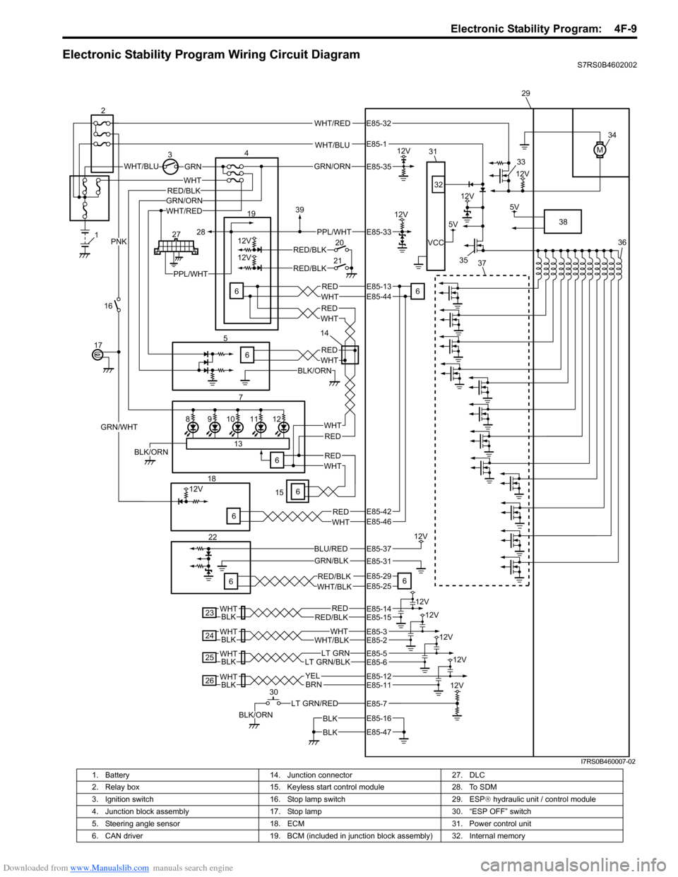
Electronic Stability Program Wiring Circuit DiagramS7RS0B4602002
WHT/BLU
WHT/BLUGRN
M
12V3
12V
5V
12V
VCC
WHT/RED
WHT
7
REDWHT
12V
12V
6 19
20
21RED/BLK
RED/BLK
GRN/WHT
PNK
12V
GRN/BLK
5V
LT GRN/RED
BLK/ORN
4
16
17
186
22
6 29
30 34
36
38
33
35
32
31
6
6 37
BLK
BLK
RED/BLKRED12V
BLKWHT
23
WHT/BLKWHT
12V
BLKWHT
24
BLKWHTLT GRN/BLKLT GRN
12V
25
BLKWHTBRN
12V
26YEL
12V
98101211
13
6BLK/ORN
1
227
5
WHT/REDGRN/ORN
BLK/ORN
REDWHT
REDWHT
PPL/WHT
6
REDWHT
REDWHT
6
REDWHT
RED/BLK
PPL/WHT
28
39
15 14
BLU/RED
GRN/ORN
12V
12V
E85-35
E85-33
E85-13E85-44
E85-46
E85-29E85-25
E85-37
E85-31
E85-14E85-15
E85-12E85-11
E85-16
E85-47
E85-3
E85-32
E85-1
E85-2
E85-5E85-6
E85-7
E85-42
RED/BLKWHT/BLK
I7RS0B460007-02
1. Battery 14. Junction connector 27. DLC
2. Relay box 15. Keyless start control module 28. To SDM
3. Ignition switch 16. Stop lamp switch 29. ESP® hydraulic unit / control module
4. Junction block assembly 17. Stop lamp 30. “ESP OFF” switch
5. Steering angle sensor 18. ECM 31. Power control unit
6. CAN driver 19. BCM (included in junction block assembly) 32. Internal memory
Page 590 of 1496
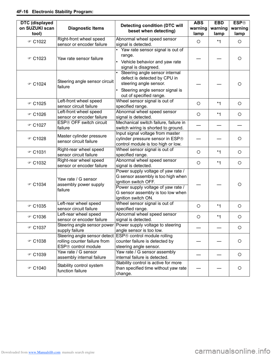
Downloaded from www.Manualslib.com manuals search engine 4F-16 Electronic Stability Program:
�) C1022 Right-front wheel speed
sensor or encoder failure Abnormal wheel speed sensor
signal is detected.
�{
*1 �{
�) C1023 Yaw rate sensor failure • Yaw rate sensor signal is out of
range.
• Vehicle behavior and yaw rate signal is disagreed. ——
�{
�) C1024 Steering angle sensor circuit
failure • Steering angle sensor internal
defect is detected by CPU in
steering angle sensor.
• Steering angle sensor signal is out of specified range. ——
�{
�) C1025 Left-front wheel speed
sensor circuit failure Wheel sensor signal is out of
specified range.
�{
*1 �{
�) C1026 Left-front wheel speed
sensor or encoder failure Abnormal wheel speed sensor
signal is detected.
�{
*1 �{
�) C1027 ESP
® OFF switch circuit
failure Mechanical switch failure, failure in
switch wiring is shorted to ground.
———
�) C1028 Master cylinder pressure
sensor circuit failure Input signal voltage from master
cylinder pressure sensor in ESP
®
control module is too high or low. ——
�{
�) C1031 Right-rear wheel speed
sensor circuit failure Wheel sensor signal is out of
specified range.
�{
*1 �{
�) C1032 Right-rear wheel speed
sensor or encoder failure Abnormal wheel speed sensor
signal is detected.
�{
*1 �{
�) C1034 Yaw rate / G sensor
assembly power supply
failure Power supply voltage of yaw rate /
G sensor assembly is too high when
ignition switch OFF.
——�{
Power supply voltage of yaw rate /
G sensor assembly is too low when
ignition switch ON.
�) C1035 Left-rear wheel speed
sensor circuit failure Wheel sensor signal is out of
specified range.
�{
*1 �{
�) C1036 Lef
t-rear wheel speed
sensor or encoder failure Abnormal wheel speed sensor
signal is detected.
�{
*1 �{
�) C1037 Steering angle sensor power
supply failure Power supply voltage to steering
angle sensor is too low.
——
�{
�) C1038 Steering angle sensor detect
rolling counter failure from
ESP
® control module ESP
® control module rolling
counter failure is detected by
steering angle sensor. ——
�{
�) C1039 Yaw rate / G sensor
assembly internal failure Yaw rate / G sensor assembly
internal failure is detected.
——
�{
�) C1040 Stability control system
function failure Stability control is active for more
than specified time
without yaw rate
change. ——
�{
DTC (displayed
on SUZUKI scan tool) Diagnostic Items
Detecting condition (DTC will
beset when detecting) ABS
warning lamp EBD
warning lamp ESP
®
warning lamp