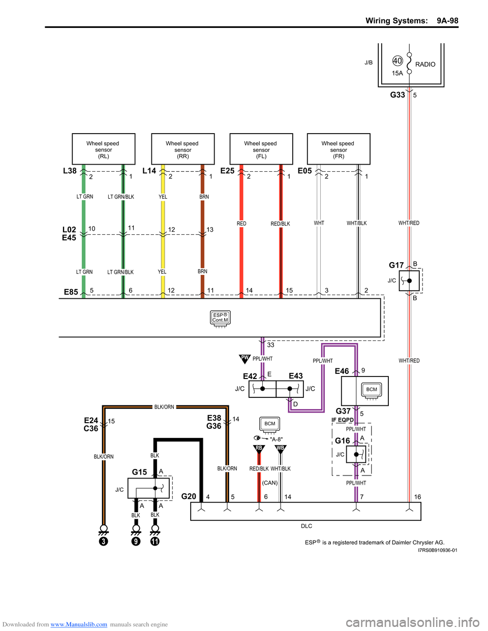
esp wiring SUZUKI SWIFT 2006 2.G Service Repair Manual
[x] Cancel search | Manufacturer: SUZUKI, Model Year: 2006, Model line: SWIFT, Model: SUZUKI SWIFT 2006 2.GPages: 1496, PDF Size: 34.44 MB
Page 1269 of 1496

Downloaded from www.Manualslib.com manuals search engine Wiring Systems: 9A-98
YEL
ESP
Cont.M
L38
LT GRN/BLKLT GRN
LT GRN/BLKLT GRN
L02
E4510
5 6 12 11 14 15 3 211
Wheel speed sensor(RL)
BRN
YELBRN
13
12
L14
Wheel speed
sensor(RR)
WHT/BLK
E05
Wheel speed sensor(FR)
WHTRED
E25
Wheel speed sensor(FL)
RED/BLK
E85
2 12 12 121
33
DLC
PPL/WHT
PPL/WHT
A
A
E38
G36
5
E42
D
J/C
G16
PPL/WHT
E
59E46
BCM
BCMPPL/WHT
WHT/RED
G20 G37
PW
WHT/BLKRED/BLK
RBWB
"A-8"
11
BLK
BLK
A
A
J/C
G15
4
E24
C3615
BLK/ORN
3
BLK/ORN
9
BLK
A
B
B
J/C
G17
15A RADIO
40
G335
WHT/RED
J/B
BLK/ORN
14
6
716
14
E43
J/C
J/C
(CAN) IF EQPD
R
RESP is a registered trademark of Daimler Chrysler AG.I7RS0B910936-01
Page 1427 of 1496

Downloaded from www.Manualslib.com manuals search engine Body Electrical Control System: 10B-24
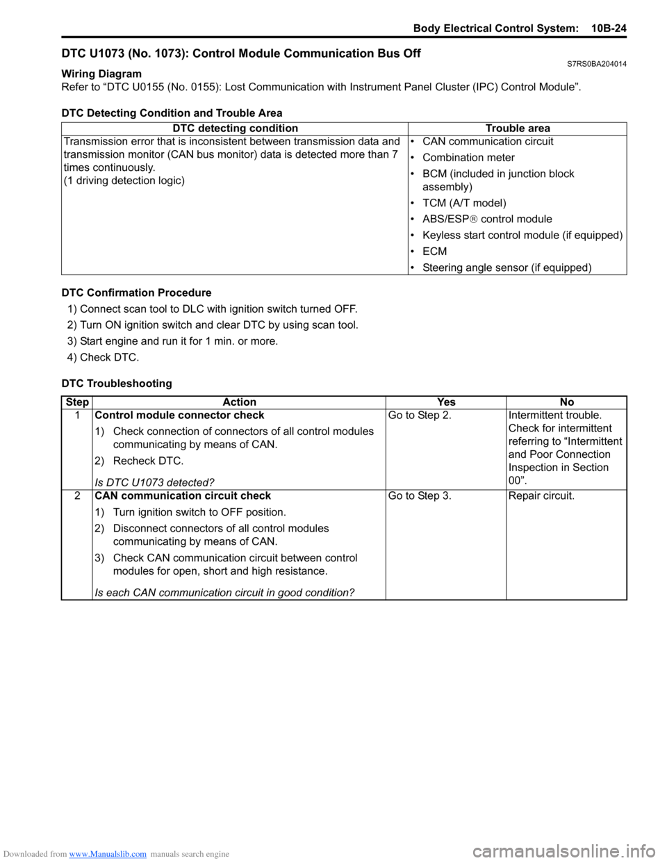
DTC U1073 (No. 1073): Control Module Communication Bus OffS7RS0BA204014
Wiring Diagram
Refer to “DTC U0155 (No. 0155): Lost Communication with Instrument Panel Cluster (IPC) Control Module”.
DTC Detecting Condition and Trouble Area
DTC Confirmation Procedure 1) Connect scan tool to DLC with ignition switch turned OFF.
2) Turn ON ignition switch and clear DTC by using scan tool.
3) Start engine and run it for 1 min. or more.
4) Check DTC.
DTC Troubleshooting DTC detecting condition Trouble area
Transmission error that is inconsistent between transmission data and
transmission monitor (CAN bus monitor) data is detected more than 7
times continuously.
(1 driving detection logic) • CAN communication circuit
• Combination meter
• BCM (included in junction block
assembly)
• TCM (A/T model)
• ABS/ESP ® control module
• Keyless start control module (if equipped)
•ECM
• Steering angle sensor (if equipped)
Step Action YesNo
1 Control module connector check
1) Check connection of connectors of all control modules
communicating by means of CAN.
2) Recheck DTC.
Is DTC U1073 detected? Go to Step 2.
Intermittent trouble.
Check for intermittent
referring to “Intermittent
and Poor Connection
Inspection in Section
00”.
2 CAN communication circuit check
1) Turn ignition switch to OFF position.
2) Disconnect connectors of all control modules
communicating by means of CAN.
3) Check CAN communication circuit between control modules for open, short and high resistance.
Is each CAN communication circuit in good condition? Go to Step 3.
Repair circuit.
Page 1447 of 1496

Downloaded from www.Manualslib.com manuals search engine Immobilizer Control System: 10C-4
Schematic and Routing Diagram
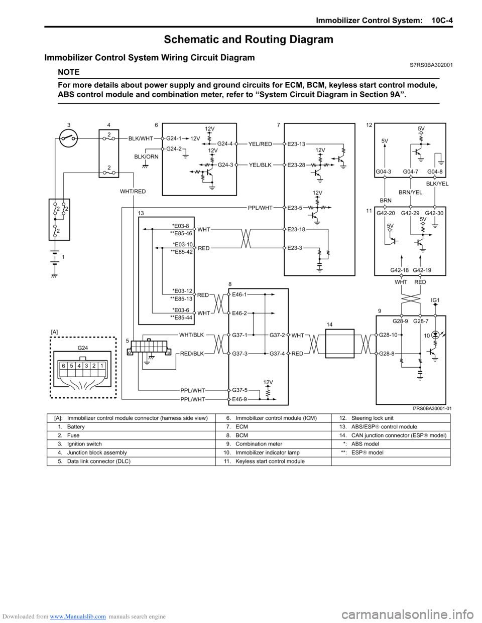
Immobilizer Control System Wiring Circuit DiagramS7RS0BA302001
NOTE
For more details about power supply and ground circuits for ECM, BCM, keyless start control module,
ABS control module and combination meter, refer to “System Ci rcuit Diagram in Section 9A”.
BLK/WHT
BLK/ORN12V
G24-1
G24-2
12V
5V
12V
12VYEL/RED
YEL/BLK
G24-4
G24-3
12V
5V
BRN
BRN/YEL
BLK/YEL
1
2
2 2
2
34
2 6712
11
9
14
12
3
4
G24
[A]
5
6
REDWHT
G42-20 G42-29 G42-30
G04-3 G04-7 G04-8
WHT/RED
5V
5V
5
G28-9 G28-7
G42-18G42-19
E23-13
E23-28
IG1
PPL/WHT 10
PPL/WHT
PPL/WHT
E23-5
RED
WHT**E85-46E23-18
E23-3
RED
WHT
E46-1
E46-2
WHT
RED
G37-2
G37-4
WHT/BLK
RED/BLK
G37-1
G37-3
12V
E46-9
G37-5
13
8
**E85-42
**E85-13
**E85-44
G28-10
G28-8
*E03-8 *E03-10
*E03-12
*E03-6
I7RS0BA30001-01
[A]: Immobilizer control module connector (harness side vi ew) 6. Immobilizer control module (ICM) 12. Steering lock unit
1. Battery 7. ECM 13. ABS/ESP ® control module
2. Fuse 8. BCM 14. CAN junction connector (ESP ® model)
3. Ignition switch 9. Combination meter *: ABS model
4. Junction block assembly 10. Immobilizer indicator lamp **: ESP ® model
5. Data link connector (DLC) 11. Keyless start control module