wipe SUZUKI SWIFT 2006 2.G Service Workshop Manual
[x] Cancel search | Manufacturer: SUZUKI, Model Year: 2006, Model line: SWIFT, Model: SUZUKI SWIFT 2006 2.GPages: 1496, PDF Size: 34.44 MB
Page 4 of 1496

Downloaded from www.Manualslib.com manuals search engine 00
0
1
2
3
4
5
6
7
8
9
10
11
Vo l u m e 1
Precautions............................................................... 00-iPrecautions ............................................................ 00-1
General Information ................ ................................... 0-i
General Information ............................................... 0A-1
Maintenance and Lubricatio n ................................. 0B-1
Engine ......................................................................... 1-i Precautions .............................................................. 1-1
Engine General Information and Diagnosis ........... 1A-1
Aux. Emission Control Devices .............................. 1B-1
Engine Electrical Devices....................................... 1C-1
Engine Mechanical ................................................. 1D-1
Engine Lubrication System .................................... 1E-1
Engine Cooling System .......................................... 1F-1
Fuel System ...........................................................1G-1
Ignition System....................................................... 1H-1
Starting System ....................................................... 1I-1
Charging System.....................................................1J-1
Exhaust System ..................................................... 1K-1
Suspension ................................................................. 2-i Precautions .............................................................. 2-1
Suspension General Diagnosis .............................. 2A-1
Front Suspension ................................................... 2B-1
Rear Suspension................ .................................... 2C-1
Wheels and Tires ................................................... 2D-1
Driveline / Axle ........................................................... 3-i Precautions .............................................................. 3-1
Drive Shaft / Axle ................................................... 3A-1
Brakes ......................................................................... 4-i Precautions .............................................................. 4-1
Brake Control System and Diagnosis .................... 4A-1
Front Brakes........................................................... 4B-1
Rear Brakes ........................................................... 4C-1
Parking Brake......................................................... 4D-1
ABS ........................................................................ 4E-1
Electronic Stability Program ................................... 4F-1
Vo l u m e 2
Precautions ............................................................... 00-iPrecautions ............................................................ 00-1
Transmission / Transaxle .... ...................................... 5-i
Precautions .............................................................. 5-1
Automatic Transmission/Transaxle ........................ 5A-1
Manual Transmission/Transaxle ............................ 5B-1
Clutch .....................................................................5C-1
Steering ....................................................................... 6-i Precautions .............................................................. 6-1
Steering General Diagnosis ................................... 6A-1
Steering Wheel and Column .................................. 6B-1
Power Assisted Steering System ...........................6C-1
HVAC ........................................................................... 7-i Precautions .............................................................. 7-1
Heater and Ventilation............................................ 7A-1
Air Conditioning System ......................................... 7B-1
Restraint ...................................................................... 8-i Precautions .............................................................. 8-1
Seat Belts ............................................................... 8A-1
Air Bag System ...................................................... 8B-1
Body, Cab and Accessories .... .................................. 9-i
Precautions .............................................................. 9-1
Wiring Systems ...................................................... 9A-1
Lighting Systems .................................................... 9B-1
Instrumentation / Driver Info. / Horn .......................9C-1
Wipers / Washers ...................................................9D-1
Glass / Windows / Mirrors ...................................... 9E-1
Security and Locks ................................................. 9F-1
Seats ..................................................................... 9G-1
Interior Trim ............................................................9H-1
Hood / Fenders / Doors .......................................... 9J-1
Body Structure ....................................................... 9K-1
Paint / Coatings ...................................................... 9L-1
Exterior Trim .......................................................... 9M-1
Control Systems ....................................................... 10-i Precautions ............................................................ 10-1
Body Electrical Control Sy stem ............................ 10B-1
Immobilizer Control System .................................10C-1
Keyless Start System ........................................... 10E-1
TABLE OF CONTENTS
Page 8 of 1496
Downloaded from www.Manualslib.com manuals search engine 00-3 Precautions:
WARNING!
SDM
• For handling and storage of a SDM, select a place where the ambient temperature
below 65 °C (150 °F), without high humidity
and away from electric noise.
• During service procedures, be very careful when handling a Sensing and Diagnostic
Module (SDM). Never strike or jar the SDM.
• Never power up the air bag system when the SDM is not rigidly attached to the
vehicle. All SDM and mounting bracket
fasteners must be carefully torqued and
the arrow must be pointing toward the
front of the vehicle to ensure proper
operation of the air bag system.
The SDM could be activated when powered
while not rigidly att ached to the vehicle
which could cause deployment and result
in personal injury.
WARNING!
Driver and Passenger Seat Belt
Pretensioners
• For handling and storage of a live seat belt pretensioner, select a place where the
ambient temperature below 65 °C (150 ° F),
without high humidity and away from
electric noise.
• Never carry seat belt pretensioner by wire or connector of pretensioner. When
placing a live seat belt pretensioner on the
workbench or some place like that, never
put something on seat belt pretensioner.
Otherwise, personal injury may result.
• Never dispose of live (inactivated) seat belt pretensioners (drive and passenger). If
disposal is necessary, be sure to activate
them according to activation procedures
described in “Air Bag (Inflator) Module and
Seat Belt Pretensioner Disposal in Section
8B” before disposal.
• The seat belt pretensioner immediately after activation is very hot. Wait for at least
half an hour to cool it off before
proceeding the work.
• With many service procedures, gloves and safety glasses should be worn to prevent
any possible irritation of the skin or eyes.
• Even when the accident was light enough not to cause air bags to activate, be sure to inspect system
parts and other related parts according to instructions
under “Repair and Inspection Required after Accident
in Section 8B”.
• When servicing parts other than air bag system, if shocks may be applied to air bag system component
parts, remove those parts beforehand.
• When handling the air bag (inflator) modules (driver, passenger, side and curtain), seat belt pretensioners
(driver and passenger), forward sensor, side sensors
or SDM, be careful not to drop it or apply an impact to
it. If an excessive impact was applied, never attempt
disassembly or repair but replace it with a new one.
• When grease, cleaning agent, oil, water, etc. has got onto air bag (inflator) modules (driver, passenger, side
and curtain) or seat belt pretensioners (drive and
passenger), wipe off immediately with a dry cloth.
• Air bag wire harness is included in floor and instrument panel wire harnesses. Air bag wire
harness branched off from floor and instrument panel
wire harnesses can be identifie d easily as it is covered
with a yellow protection tube and it has yellow
connectors. Be very ca reful when handling it.
• When an open in air bag wire harness, damaged wire harness, connector or terminal is found, replace wire
harness, connectors and terminals as an assembly.
• Do not apply power to the air bag system unless all components are connected or a diagnostic flow
requests it, as this will set a DTC.
• Never use air bag system component parts from another vehicle.
• When using electric welding, be sure to disconnect all air bag (inflator) module connectors and pretensioner
connectors from air bag wire harness respectively.
• Never expose air bag system component parts directly to hot air (drying or baking the vehicle after
painting) or flames.
• WARNING / CAUTION labels are attached on each
part of air bag system components. Be sure to follow
the instructions.
• After vehicle is completely repaired, perform “Air Bag Diagnostic System Check in Section 8B”.
Page 34 of 1496
Downloaded from www.Manualslib.com manuals search engine 0B-4 Maintenance and Lubrication:
Accessory Drive Belt ReplacementS7RS0B0206002
Water Pump and Generator Drive Belt
Replace belt with new one referring to “Water Pump /
Generator Drive Belt Removal and Installation in Section
1J”.
A/C Compressor Drive Belt
Replace belt with new one referring to “Compressor
Drive Belt Removal and Inst allation in Section 7B”.
Valve Lash (Clearance) InspectionS7RS0B0206003
Inspect intake and exhaust valve lash and adjust as
necessary.
Refer to “Valve Lash (Clearance) Inspection in Section
1D” for valve lash inspection and adjustment procedure.
Engine Oil and Filter ChangeS7RS0B0206004
WARNING!
• New and used engine oil can be
hazardous.
Be sure to read “WARNING” in “General
Precautions in Section 00” and observe
what is written there.
• Step 1) – 7) outlined below must be performed with ENGINE NOT RUNNING.
For Step 8), be sure to have adequate
ventilation while engine is running.
Before draining engine oil, check engine for oil leakage.
If any evidence of leakage is found, make sure to correct
defective part before proceeding to the following work.
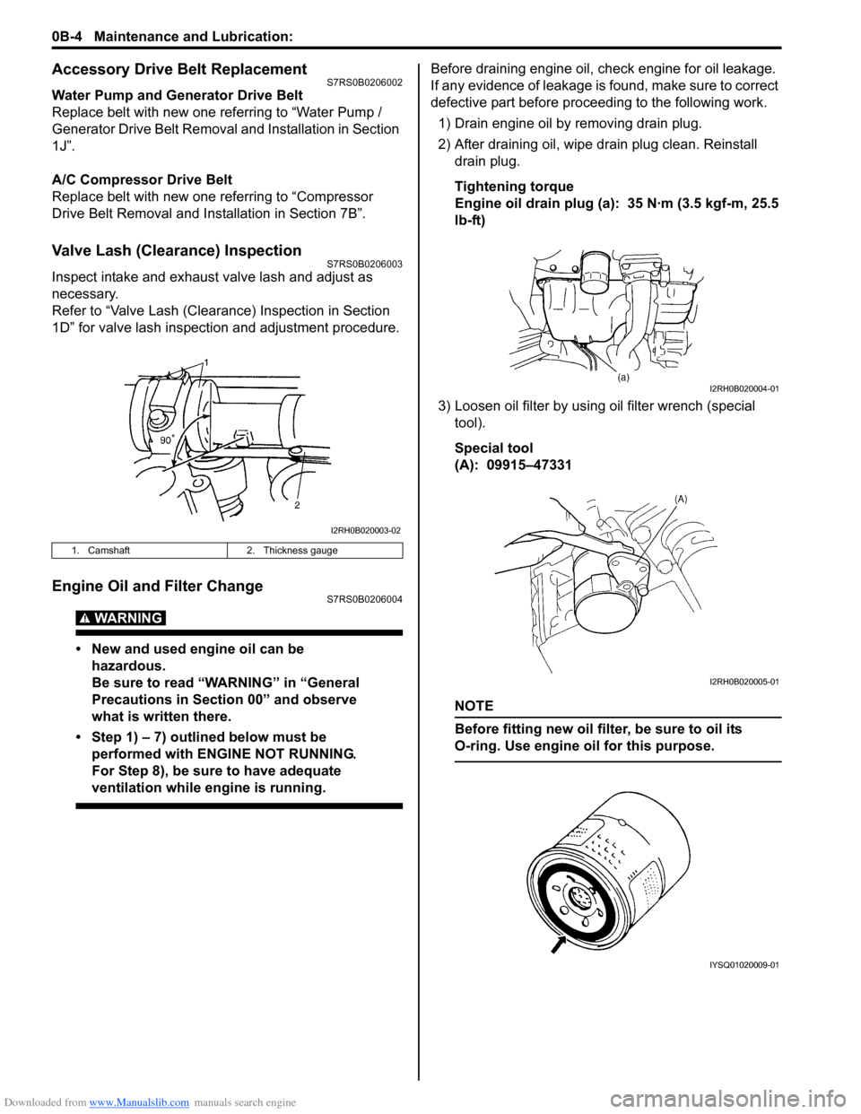
1) Drain engine oil by removing drain plug.
2) After draining oil, wipe drain plug clean. Reinstall drain plug.
Tightening torque
Engine oil drain plug (a): 35 N·m (3.5 kgf-m, 25.5
lb-ft)
3) Loosen oil filter by using oil filter wrench (special
tool).
Special tool
(A): 09915–47331
NOTE
Before fitting new oil filter, be sure to oil its
O-ring. Use engine oil for this purpose.
1. Camshaft 2. Thickness gauge
I2RH0B020003-02
I2RH0B020004-01
I2RH0B020005-01
IYSQ01020009-01
Page 266 of 1496
Downloaded from www.Manualslib.com manuals search engine 1A-216 Engine General Information and Diagnosis:
Repair Instructions
Idle Speed and IAC Throttle Valve Opening
Inspection
S7RS0B1106001
Before idle speed check, make sure of the following.
• Lead wires and hoses of electronic fuel injection and engine and emission control systems are connected
securely.
• Valve lash is checked according to maintenance schedule.
• Ignition timing is within specification.
• All accessories (wipers, heater, lights, A/C, etc.) are out of service.
• Air cleaner has been properly installed and is in good condition.
• No abnormal air drawn in from air intake system.
After all items are confirmed, check idle speed and IAC
duty as follows.
NOTE
Before starting engine, place transmission
gear shift lever in “Neutral” (shift selector
lever to “P” range for A/T vehicle), and set
parking brake and block drive wheels.
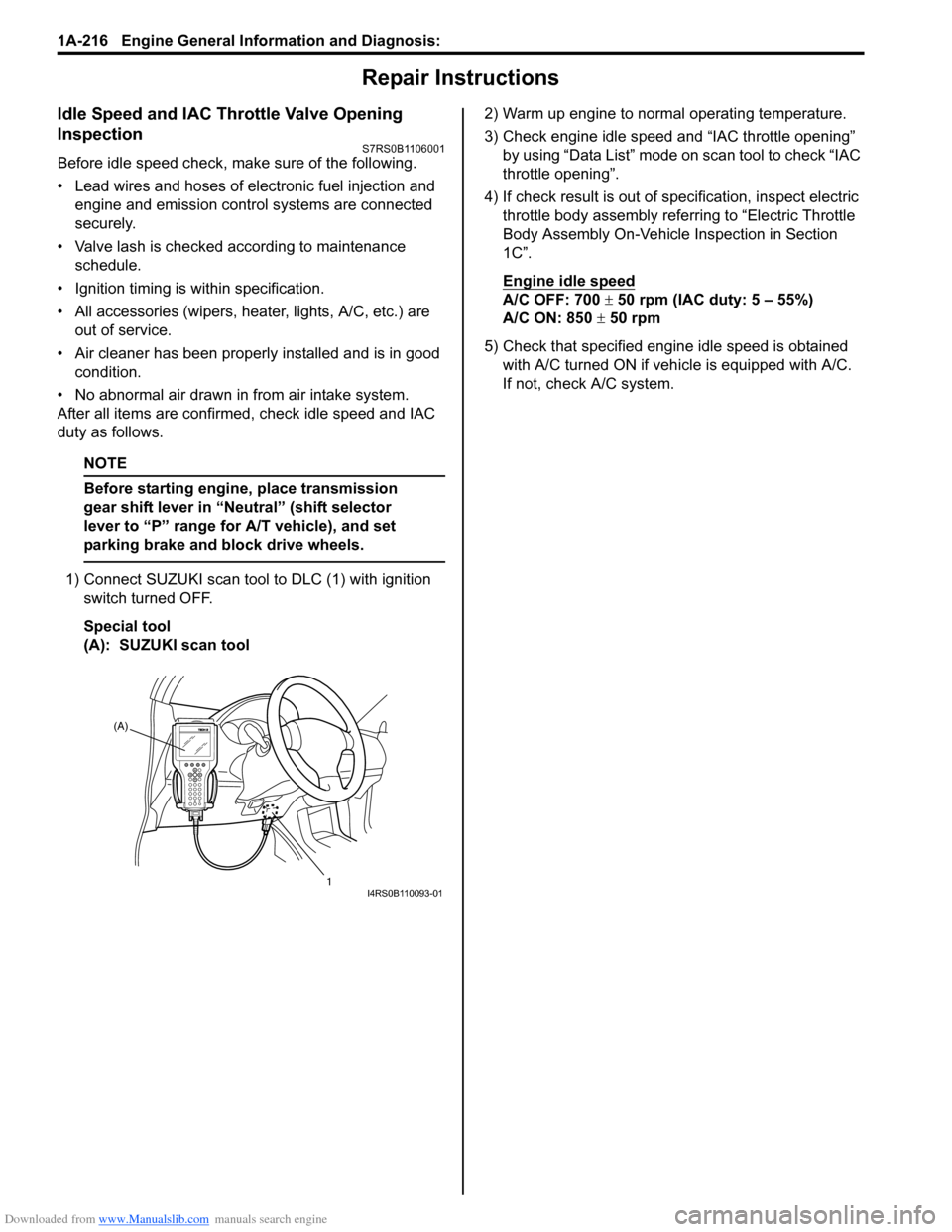
1) Connect SUZUKI scan tool to DLC (1) with ignition
switch turned OFF.
Special tool
(A): SUZUKI scan tool 2) Warm up engine to normal operating temperature.
3) Check engine idle speed and “IAC throttle opening”
by using “Data List” mode on scan tool to check “IAC
throttle opening”.
4) If check result is out of sp ecification, inspect electric
throttle body assembly referring to “Electric Throttle
Body Assembly On-Vehicle Inspection in Section
1C”.
Engine idle speed
A/C OFF: 700 ± 50 rpm (IAC duty: 5 – 55%)
A/C ON: 850 ± 50 rpm
5) Check that specified engine idle speed is obtained with A/C turned ON if vehi cle is equipped with A/C.
If not, check A/C system.
(A)
1
I4RS0B110093-01
Page 415 of 1496
Downloaded from www.Manualslib.com manuals search engine Charging System: 1J-5
Generator Test (Undercharged Battery Check)S7RS0B1A04003
This condition, as evidenced by slow cranking or
indicator clear with dark or light yellow dot can be
caused by one or more of the following conditions even
though indicator lamp may be operating normal.
The following procedure also applies to cars with
voltmeter and ammeter.1) Make sure that undercharged condition has not been caused by accessories left on for extended period of
time.
2) Check drive belt for proper tension.
3) If battery defect is suspected, refer to “Battery Description”.
4) Inspect wiring for defects. Check all connections for tightness and cleanliness, battery cable connections
at battery, starting motor, ignition ground cable and
no “C” terminal circuit at ground.
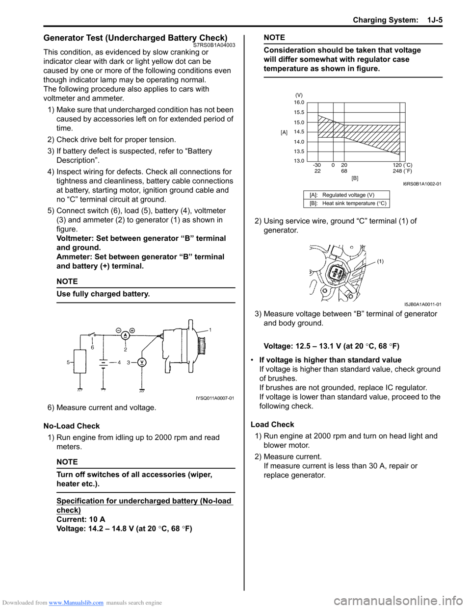
5) Connect switch (6), load (5), battery (4), voltmeter (3) and ammeter (2) to generator (1) as shown in
figure.
Voltmeter: Set between generator “B” terminal
and ground.
Ammeter: Set between generator “B” terminal
and battery (+) terminal.
NOTE
Use fully charged battery.
6) Measure current and voltage.
No-Load Check 1) Run engine from idling up to 2000 rpm and read meters.
NOTE
Turn off switches of all accessories (wiper,
heater etc.).
Specification for undercharged battery (No-load
check)
Current: 10 A
Voltage: 14.2 – 14.8 V (at 20 °C, 68 °F)
NOTE
Consideration should be taken that voltage
will differ somewhat with regulator case
temperature as shown in figure.
2) Using service wire, ground “C” terminal (1) of
generator.
3) Measure voltage between “B” terminal of generator and body ground.
Voltage: 12.5 – 13.1 V (at 20 °C, 68 °F)
• If voltage is higher than standard value
If voltage is higher than standard value, check ground
of brushes.
If brushes are not grounded, replace IC regulator.
If voltage is lower than standard value, proceed to the
following check.
Load Check 1) Run engine at 2000 rpm and turn on head light and blower motor.
2) Measure current. If measure current is less than 30 A, repair or
replace generator.
IYSQ011A0007-01
[A]: Regulated voltage (V)
[B]: Heat sink temperature ( °C)
16.0
15.5
15.0
14.5
14.0
13.5
13.0
-30 0 20
[A]
[B]
68
22120 (˚C)
248 (˚F)
(V)
I6RS0B1A1002-01
I5JB0A1A0011-01
Page 437 of 1496
Downloaded from www.Manualslib.com manuals search engine Front Suspension: 2B-4
Reference Information
Side slip
When checked with side slip tester, side slip should
satisfy following specification.Side slip
0 to IN 3.0 mm/m (0 to IN 0.118 in/3.3 ft)
If side slip is greatly di
fferent, toe or front wheel
alignment may not be correct.
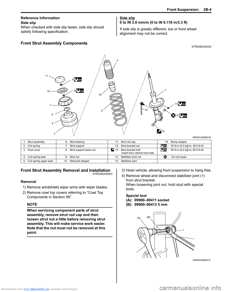
Front Strut Assembly ComponentsS7RS0B2206002
Front Strut Assembly Removal and InstallationS7RS0B2206003
Removal
1) Remove windshield wipe r arms with wiper blades.
2) Remove cowl top covers referring to “Cowl Top
Components in Section 9K”.
NOTE
When servicing component parts of strut
assembly, remove stru t rod cap and then
loosen strut nut a little before removing strut
assembly. This will make service work easier.
Note that the nut must not be removed at this
point.
3) Hoist vehicle, allowing front suspension to hang free.
4) Remove wheel and disconn ect stabilizer joint (1)
from strut bracket.
When loosening joint nu t, hold stud with special
tools.
Special tool
(A): 09900–00411 socket
(B): 09900–00413 5 mm
11 3
2 1
12
13
4
5
6
7
10
8(a)
(b)
9
(a)
14
15(a)
16
I6RS0C220006-02
1. Strut assembly
6. Strut bearing 11. Strut rod cap16. Bump stopper
2. Coil spring 7. Strut support 12. Strut bracket nut : 50 N⋅m (5.0 kgf-m, 36.5 lb-ft)
3. Dust cover 8. Strut support lower nut 13. Strut bracket bolt
:Insert from vehicle front side. : 90 N
⋅m (9.0 kgf-m, 65.5 lb-ft)
4. Coil spring seat 9. Strut nut 14. Stabilizer joint nut : Do not reuse.
5. Coil spring upper seat 10. Rebound stopper 15. Stabilizer joint
1
(A)
(B)
I4RS0A220004-01
Page 438 of 1496
Downloaded from www.Manualslib.com manuals search engine 2B-5 Front Suspension:
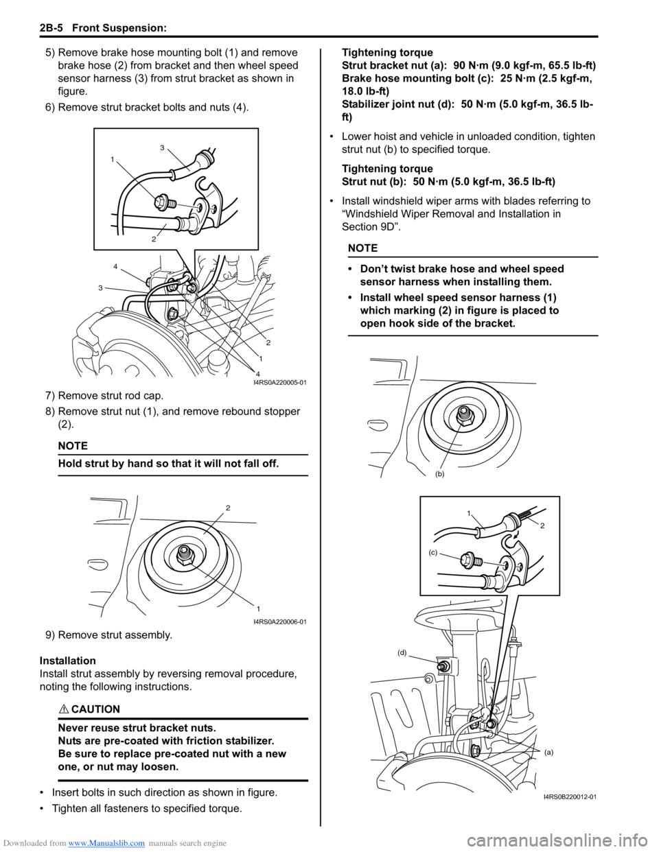
5) Remove brake hose mounting bolt (1) and remove brake hose (2) from bracket and then wheel speed
sensor harness (3) from strut bracket as shown in
figure.
6) Remove strut bracket bolts and nuts (4).
7) Remove strut rod cap.
8) Remove strut nut (1), and remove rebound stopper (2).
NOTE
Hold strut by hand so th at it will not fall off.
9) Remove strut assembly.
Installation
Install strut assembly by reversing removal procedure,
noting the following instructions.
CAUTION!
Never reuse strut bracket nuts.
Nuts are pre-coated with friction stabilizer.
Be sure to replace pre-coated nut with a new
one, or nut may loosen.
• Insert bolts in such direction as shown in figure.
• Tighten all fasteners to specified torque. Tightening torque
Strut bracket nut (a): 90 N·m (9.0 kgf-m, 65.5 lb-ft)
Brake hose mounting bolt (c): 25 N·m (2.5 kgf-m,
18.0 lb-ft)
Stabilizer joint nut (d): 50 N·m (5.0 kgf-m, 36.5 lb-
ft)
• Lower hoist and vehicle in unloaded condition, tighten strut nut (b) to specified torque.
Tightening torque
Strut nut (b): 50 N·m (5.0 kgf-m, 36.5 lb-ft)
• Install windshield wiper arms with blades referring to
“Windshield Wiper Removal and Installation in
Section 9D”.
NOTE
• Don’t twist brake hose and wheel speed sensor harness when installing them.
• Install wheel speed sensor harness (1) which marking (2) in figure is placed to
open hook side of the bracket.
1 3
2
2
1
4
4
3
I4RS0A220005-01
2
1
I4RS0A220006-01
(d) (a)
(b)
(c)
1
2
I4RS0B220012-01
Page 484 of 1496
Downloaded from www.Manualslib.com manuals search engine 3A-6 Drive Shaft / Axle:
Front Drive Shaft Disassembly and ReassemblyS7RS0B3106004
Disassembly
Tripod joint
CAUTION!
• Disassembly of wheel side joint is not allowed. If any noise or damage exists in it,
replace it as assembly.
• Do not disassemble tripod joint spider. If any malcondition is found in it, replace it
as differential side joint assembly.
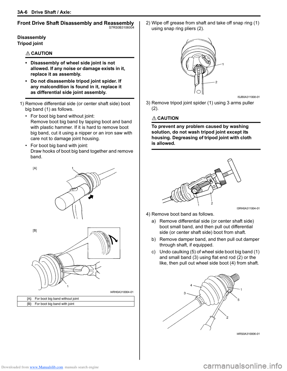
1) Remove differential side (or center shaft side) boot
big band (1) as follows.
• For boot big band without joint:Remove boot big band by tapping boot and band
with plastic hammer. If it is hard to remove boot
big band, cut it using a nipper or an iron saw with
care not to damage joint housing.
• For boot big band with joint: Draw hooks of boot big band together and remove
band. 2) Wipe off grease from shaft and take off snap ring (1)
using snap ring pliers (2).
3) Remove tripod joint spid er (1) using 3 arms puller
(2).
CAUTION!
To prevent any problem caused by washing
solution, do not wash tripod joint except its
housing. Degreasing of tr ipod joint with cloth
is allowed.
4) Remove boot band as follows.
a) Remove differential side (or center shaft side) boot small band, and then pull out differential
side (or center shaft side) boot from shaft.
b) Remove damper band, and then pull out damper through shaft, if equipped.
c) Undo caulking (5) of wheel side boot big band (1) and small band (3) using flat end rod (2) or the
like, then pull out wheel side boot (4) from shaft.
[A]: For boot big band without joint
[B]: For boot big band with joint
I4RH0A310004-01
I5JB0A311008-01
I3RH0A311004-01
I4RS0A310006-01
Page 485 of 1496
Downloaded from www.Manualslib.com manuals search engine Drive Shaft / Axle: 3A-7
DOJ
CAUTION!
Disassembly of wheel side joint is not
allowed. If any noise or damage exists in it,
replace it as assembly.
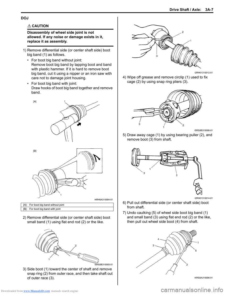
1) Remove differential side (or center shaft side) boot big band (1) as follows.
• For boot big band without joint:Remove boot big band by tapping boot and band
with plastic hammer. If it is hard to remove boot
big band, cut it using a nipper or an iron saw with
care not to damage joint housing.
• For boot big band with joint: Draw hooks of boot big band together and remove
band.
2) Remove differential side (or center shaft side) boot small band (1) using flat end rod (2) or the like.
3) Side boot (1) toward the center of shaft and remove snap ring (2) from outer race, and then take shaft out
of outer race (3). 4) Wipe off grease and remove circlip (1) used to fix
cage (2) by using snap ring pliers (3).
5) Draw away cage (1) by using bearing puller (2), and remove boot (3) from shaft.
6) Pull out differential side (or center shaft side) boot from shaft.
7) Undo caulking (5) of wheel side boot big band (1) and small band (3) using flat end rod (2) or the like,
then pull out wheel side boot (4) from shaft.
[A]: For boot big band without joint
[B]: For boot big band with joint
I4RH0A310004-01
2
1
I5RS0B310005-01
I2RH01310012-01
I5RS0B310006-01
I2RH01310014-01
I4RS0A310006-01
Page 507 of 1496
Downloaded from www.Manualslib.com manuals search engine Brake Control System and Diagnosis: 4A-9
Air Bleeding of Brake SystemS7RS0B4106006
CAUTION!
Brake fluid is extremely damaging to paint. If
fluid should accidentally touch painted
surface, immediately wipe fluid from paint
and clean painted surface.
Bleeding operation is necessary to remove air whenever
it entered hydraulic brake system.
Hydraulic lines of brake system are based on the
diagonal split system. When a brake pipe or hose was
disconnected at the wheel, bleeding operation must be
performed at both ends of the line of the removed pipe or
hose. When any joint part of the master cylinder of other
joint part between the master cylinder and each brake
(wheel) was removed, the hydraulic brake system must
be bled at all 4 wheel brakes.
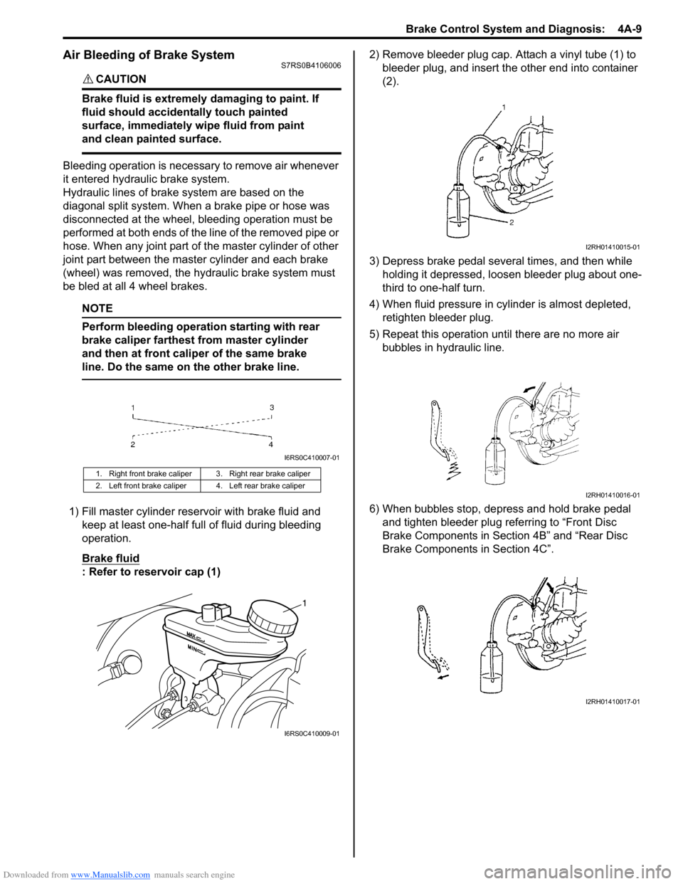
NOTE
Perform bleeding operation starting with rear
brake caliper farthest from master cylinder
and then at front caliper of the same brake
line. Do the same on the other brake line.
1) Fill master cylinder rese rvoir with brake fluid and
keep at least one-half full of fluid during bleeding
operation.
Brake fluid
: Refer to reservoir cap (1) 2) Remove bleeder plug cap. Attach a vinyl tube (1) to
bleeder plug, and insert the other end into container
(2).
3) Depress brake pedal several times, and then while holding it depressed, loosen bleeder plug about one-
third to one-half turn.
4) When fluid pressure in cy linder is almost depleted,
retighten bleeder plug.
5) Repeat this operation until there are no more air bubbles in hydraulic line.
6) When bubbles stop, depress and hold brake pedal and tighten bleeder plug referring to “Front Disc
Brake Components in Section 4B” and “Rear Disc
Brake Components in Section 4C”.
1. Right front brake caliper 3. Right rear brake caliper
2. Left front brake caliper 4. Left rear brake caliper
I6RS0C410007-01
1
I6RS0C410009-01
I2RH01410015-01
I2RH01410016-01
I2RH01410017-01