Vin SUZUKI SWIFT 2006 2.G Service Workshop Manual
[x] Cancel search | Manufacturer: SUZUKI, Model Year: 2006, Model line: SWIFT, Model: SUZUKI SWIFT 2006 2.GPages: 1496, PDF Size: 34.44 MB
Page 470 of 1496
Downloaded from www.Manualslib.com manuals search engine 2D-3 Wheels and Tires:
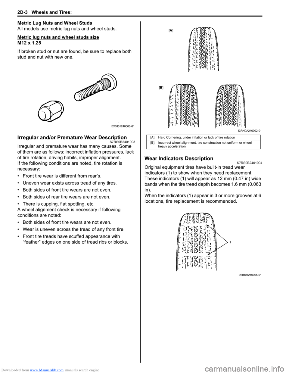
Metric Lug Nuts and Wheel Studs
All models use metric lug nuts and wheel studs.
Metric lug nuts and wheel studs size
M12 x 1.25
If broken stud or nut are found, be sure to replace both
stud and nut with new one.
Irregular and/or Premature Wear DescriptionS7RS0B2401003
Irregular and premature wear has many causes. Some
of them are as follows: incorrect inflation pressures, lack
of tire rotation, driving habits, improper alignment.
If the following conditions are noted, tire rotation is
necessary:
• Front tire wear is different from rear’s.
• Uneven wear exists across tread of any tires.
• Both sides of front tire wears are not even.
• Both sides of rear tire wears are not even.
• There is cupping, flat spotting, etc.
A wheel alignment check is necessary if following
conditions are noted:
• Both sides of front tire wears are not even.
• Wear is uneven across the tread of any front tire.
• Front tire treads have scuffed appearance with “feather” edges on one side of tread ribs or blocks.
Wear Indicators DescriptionS7RS0B2401004
Original equipment tires have built-in tread wear
indicators (1) to show when they need replacement.
These indicators (1) will app ear as 12 mm (0.47 in) wide
bands when the tire tread depth becomes 1.6 mm (0.063
in).
When the indicators (1) appear in 3 or more grooves at 6
locations, tire replacement is recommended.
I2RH01240003-01
[A]: Hard Cornering, under inflation or lack of tire rotation
[B]: Incorrect wheel alignment, tire construction not uniform or wheel heavy acceleration
I3RH0A240002-01
I2RH01240005-01
Page 471 of 1496
Downloaded from www.Manualslib.com manuals search engine Wheels and Tires: 2D-4
Radial Tire Waddle DescriptionS7RS0B2401005
Waddle is side to side movement at the front and/or rear
of the vehicle. It is caused by the steel belt not being
straight within the tire. It is most noticeable at a low
speed, 8 to 48 kph (5 to 30 mph).
It is possible to locate the f aulty tire by road testing the
vehicle. If it is on the rear , the rear end of the vehicle
shakes from side to side or “waddles”. To the driver in
the seat, it feels as though someone is pushing on the
side of vehicle.
If the faulty tire is on the front, waddling is more visual.
The front sheet metal appears to be moving back and
forth and the driver feels as though he is at the pivot
point in vehicle.
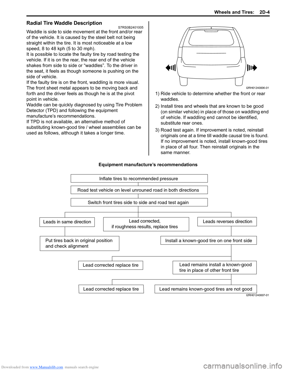
Waddle can be quickly diagnosed by using Tire Problem
Detector (TPD) and following the equipment
manufacture’s recommendations.
If TPD is not available, an alternative method of
substituting known-good tire / wheel assemblies can be
used as follows, although it takes a longer time. 1) Ride vehicle to determine whether the front or rear
waddles.
2) Install tires and wheels that are known to be good (on similar vehicle) in place of those on waddling end
of vehicle. If waddling end cannot be identified,
substitute rear ones.
3) Road test again. If improvement is noted, reinstall originals one at a time till w addle causal tire is found.
If no improvement is noted, install known-good tires
in place of all four. Then reinstall originals in the
same manner.
Equipment manufacture’s recommendations
I2RH01240006-01
Inflate tires to recommended pressure
Road test vehicle on level unrouned road in both directions
Switch front tires side to side and road test again
Lead corrected,
if roughness results, replace tiresLeads in same directionLeads reverses direction
Put tires back in original position
and check alignmentInstall a known-good tire on one front side
Lead remains install a known-good
tire in place of other front tire
Lead remains known-good tires are not goodLead corrected replace tire
Lead corrected replace tire
I2RH01240007-01
Page 474 of 1496
Downloaded from www.Manualslib.com manuals search engine 2D-7 Wheels and Tires:
Wheel Removal and InstallationS7RS0B2406003
Removal
WARNING!
Do not removal all of the wheel nuts at once,
because all the wheels of this vehicle are
mounted by the wheel nuts.
Leave a nut at least not to drop the wheel.
Support the wheel and/or tire and then
remove the nut(s) left with the wheel.
1) Loosen wheel nuts by approximately 180° (half a
rotation).
2) Hoist vehicle.
3) Make sure that the vehicle will not fall off by trying to
move vehicle body in both ways.
4) Remove wheel nut except one.
5) Support the wheel and/or tire not to drop the wheel and then remove the nut left with the wheel.
CAUTION!
Never use heat to loosen tight wheel because
the application of heat to wheel causes the
wheel life shorter and the wheel bearing
damage.
Installation
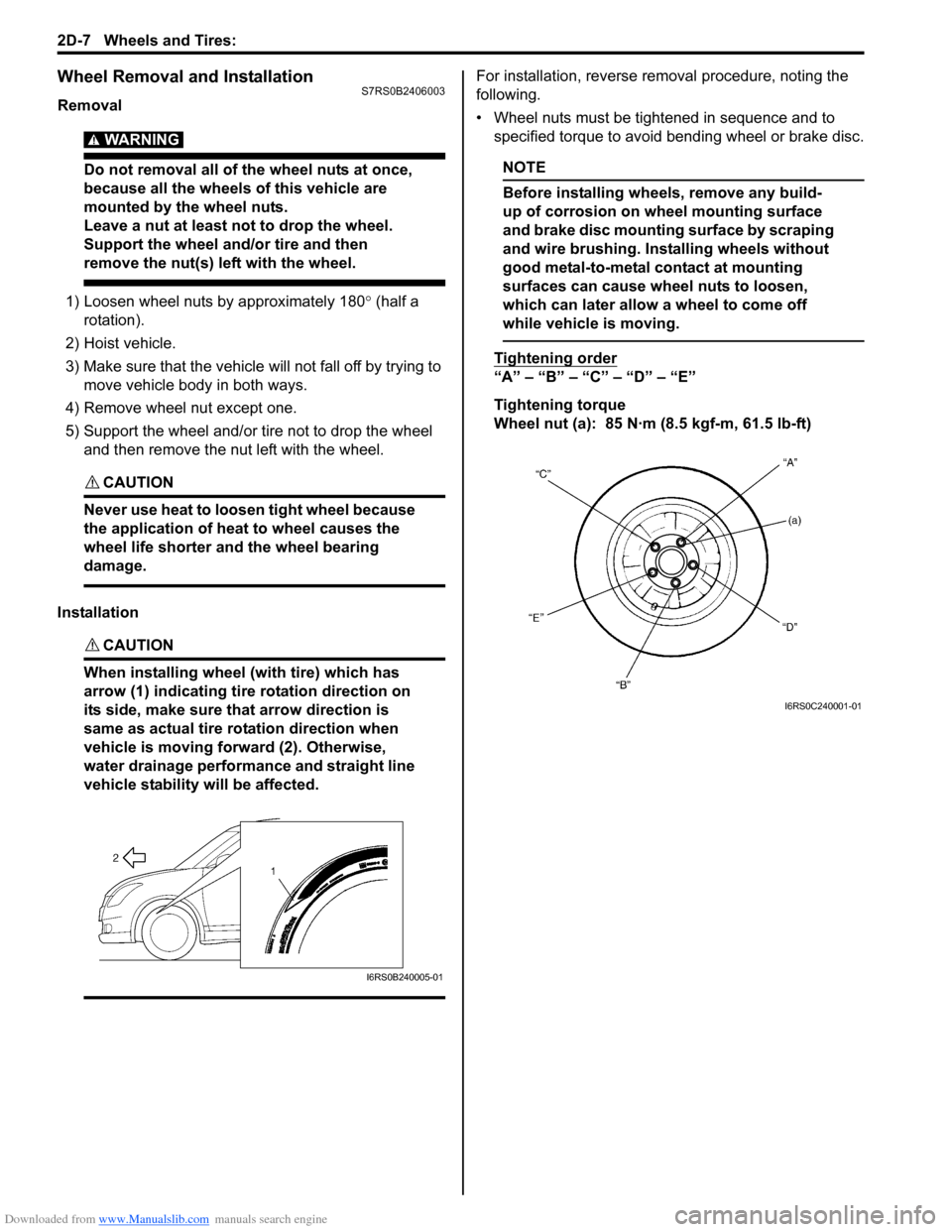
CAUTION!
When installing wheel (with tire) which has
arrow (1) indicating tire rotation direction on
its side, make sure that arrow direction is
same as actual tire ro tation direction when
vehicle is moving forw ard (2). Otherwise,
water drainage performance and straight line
vehicle stability will be affected.
For installation, reverse removal procedure, noting the
following.
• Wheel nuts must be tightened in sequence and to specified torque to avoid bending wheel or brake disc.
NOTE
Before installing wheels, remove any build-
up of corrosion on wheel mounting surface
and brake disc mounting surface by scraping
and wire brushing. Installing wheels without
good metal-to-metal contact at mounting
surfaces can cause wheel nuts to loosen,
which can later allow a wheel to come off
while vehicle is moving.
Tightening order
“A” – “B” – “C” – “D” – “E”
Tightening torque
Wheel nut (a): 85 N·m (8.5 kgf-m, 61.5 lb-ft)
I6RS0B240005-01
I6RS0C240001-01
Page 475 of 1496
Downloaded from www.Manualslib.com manuals search engine Wheels and Tires: 2D-8
Tire Mounting and DismountingS7RS0B2406004
CAUTION!
When installing tire which has arrow
indicating tire rotation direction to wheel,
make sure that this tire rotation direction is
same as actual tire rotation direction when
vehicle is moving forward. Otherwise, it is
not possible to install wheel with tire to
vehicle in specified direction.
Use a tire changing machine to mount or dismount tires.
Follow equipment manufacturer’s instructions. Do not
use hand tools or tire irons al one to change tires as they
may damage tire beads or wheel rim.
Rim bead seats should be cleaned with a wire brush or
coarse steel wool to remove lubricants, old rubber and
light rust. Before mounting or dismounting a tire, bead
area should be well lubricated with approved tire
lubricant.
After mounting, inflate to specified pressure shown on
tire placard so that beads are completely seated.
WARNING!
Do not stand over tire when inflating. Bead
may break when bead snaps over rim’s safety
hump and cause serious personal injury.
Do not exceed 330 kpa (47.9 psi) pressure
when inflating. If 330 kpa (47.9 psi) pressure
will not seat beads, deflate, re-lubricate and
reinflate.
Over inflation may cause bead to break and
cause serious personal injury.
Install valve core and inflate to proper pressure.
Tire RepairS7RS0B2406005
There are many different materials and techniques on
the market to repair tires. As not all of these work on all
types of tires, tire manufacturers have published detailed
instructions on how and when to repair tires. These
instructions can be obtained from each tire
manufacturer.
Tire Repair for Emergency Repaired-Tire with
Sealant
S7RS0B2406006
WARNING!
Be sure to observe “Precaution for
Emergency Flat Tire Repair Kit”. Otherwise,
your health may be ruined.
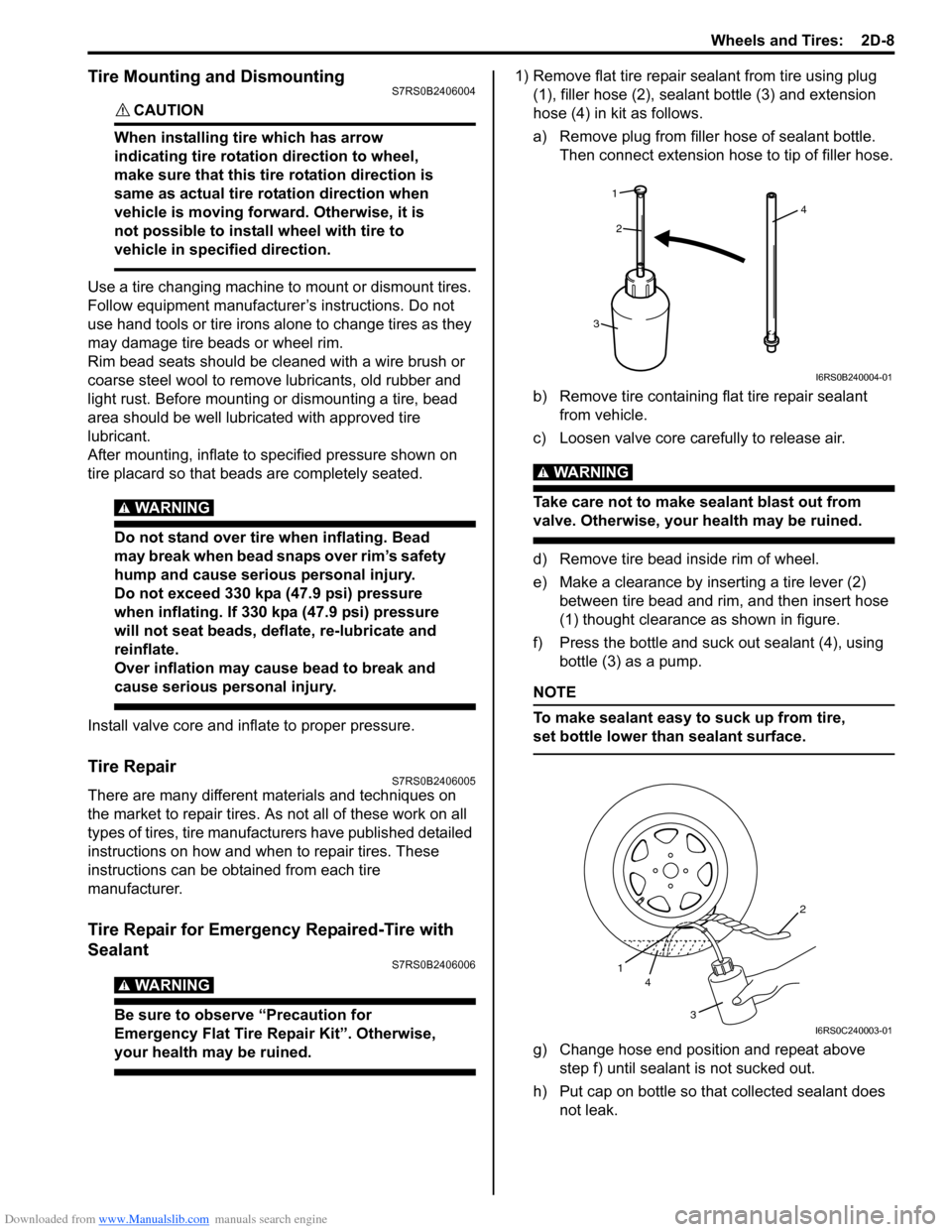
1) Remove flat tire repair sealant from tire using plug (1), filler hose (2), sealant bottle (3) and extension
hose (4) in kit as follows.
a) Remove plug from fille r hose of sealant bottle.
Then connect ext ension hose to tip of filler hose.
b) Remove tire containing flat tire repair sealant from vehicle.
c) Loosen valve core carefully to release air.
WARNING!
Take care not to make sealant blast out from
valve. Otherwise, your health may be ruined.
d) Remove tire bead inside rim of wheel.
e) Make a clearance by inserting a tire lever (2) between tire bead and rim, and then insert hose
(1) thought clearance as shown in figure.
f) Press the bottle and suck out sealant (4), using bottle (3) as a pump.
NOTE
To make sealant easy to suck up from tire,
set bottle lower than sealant surface.
g) Change hose end position and repeat above step f) until sealant is not sucked out.
h) Put cap on bottle so that collected sealant does not leak.
4
1
2
3
I6RS0B240004-01
1 4
3 2
I6RS0C240003-01
Page 500 of 1496
Downloaded from www.Manualslib.com manuals search engine 4A-2 Brake Control System and Diagnosis:
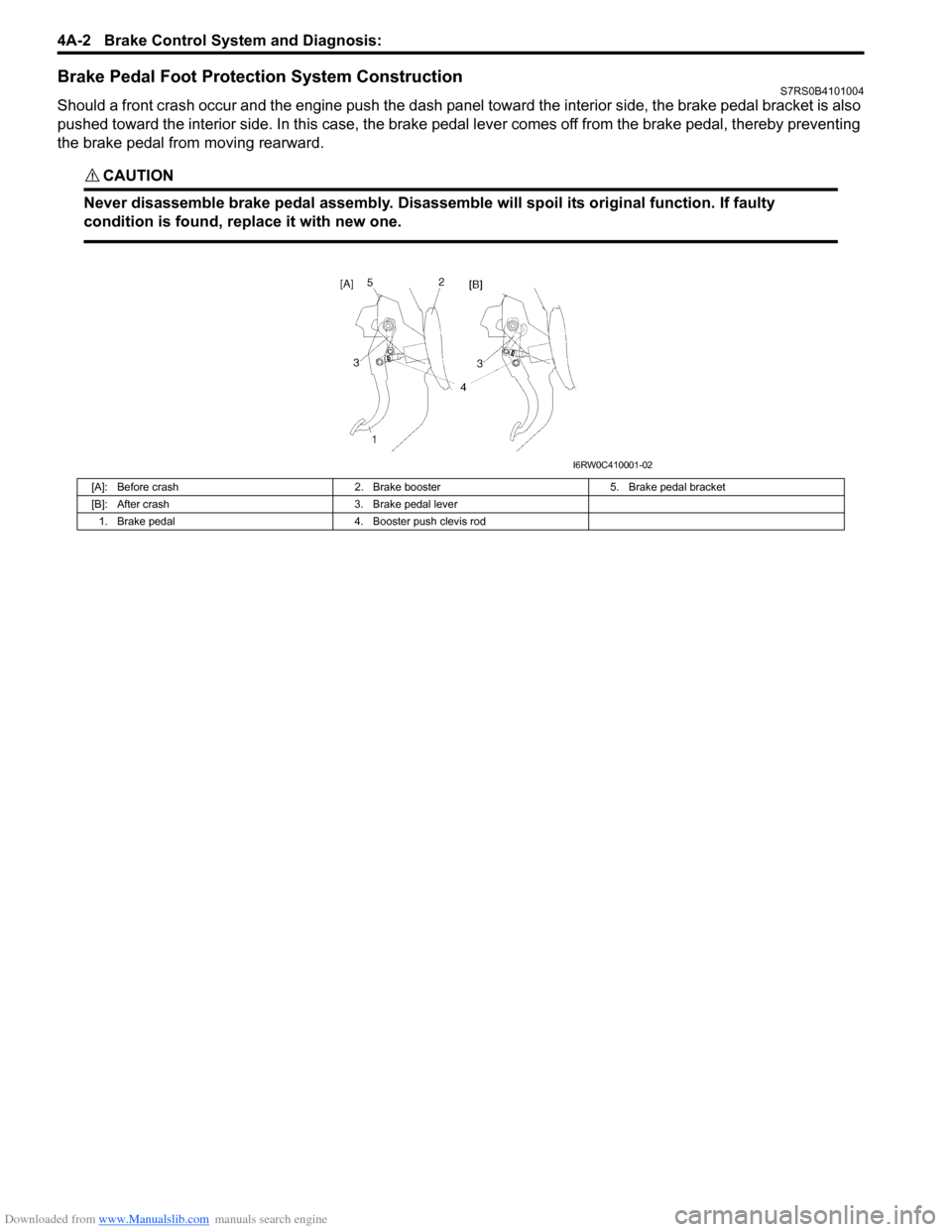
Brake Pedal Foot Protection System ConstructionS7RS0B4101004
Should a front crash occur and the engine push the dash panel toward the interior side, the brake pedal bracket is also
pushed toward the interior side. In this case, the brake pedal lever comes off from the brake pedal, thereby preventing
the brake pedal from moving rearward.
CAUTION!
Never disassemble brake pedal assembly. Disassemble will spoil its original function. If faulty
condition is found, replace it with new one.
[A]: Before crash2. Brake booster5. Brake pedal bracket
[B]: After crash 3. Brake pedal lever
1. Brake pedal 4. Booster push clevis rod
I6RW0C410001-02
Page 506 of 1496
Downloaded from www.Manualslib.com manuals search engine 4A-8 Brake Control System and Diagnosis:
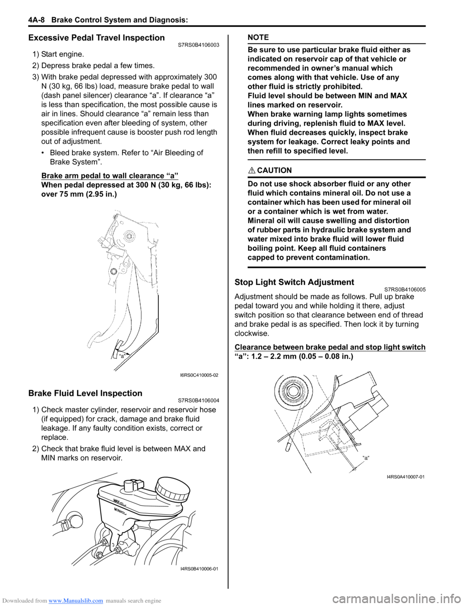
Excessive Pedal Travel InspectionS7RS0B4106003
1) Start engine.
2) Depress brake pedal a few times.
3) With brake pedal depressed with approximately 300 N (30 kg, 66 lbs) load, measure brake pedal to wall
(dash panel silencer) clearance “a”. If clearance “a”
is less than specification, the most possible cause is
air in lines. Should clearance “a” remain less than
specification even after bleeding of system, other
possible infrequent cause is booster push rod length
out of adjustment.
• Bleed brake system. Refer to “Air Bleeding of Brake System”.
Brake arm pedal to wall clearance “a”
When pedal depressed at 300 N (30 kg, 66 lbs):
over 75 mm (2.95 in.)
Brake Fluid Level InspectionS7RS0B4106004
1) Check master cylinder, reservoir and reservoir hose (if equipped) for crack, damage and brake fluid
leakage. If any faulty condition exists, correct or
replace.
2) Check that brake fluid level is between MAX and MIN marks on reservoir.
NOTE
Be sure to use particular brake fluid either as
indicated on reservoir cap of that vehicle or
recommended in owner’s manual which
comes along with that vehicle. Use of any
other fluid is strictly prohibited.
Fluid level should be between MIN and MAX
lines marked on reservoir.
When brake warning lamp lights sometimes
during driving, replenis h fluid to MAX level.
When fluid decreases quickly, inspect brake
system for leakage. Correct leaky points and
then refill to specified level.
CAUTION!
Do not use shock absorber fluid or any other
fluid which contains mineral oil. Do not use a
container which has been used for mineral oil
or a container which is wet from water.
Mineral oil will cause swelling and distortion
of rubber parts in hydraulic brake system and
water mixed into brake fluid will lower fluid
boiling point. Keep all fluid containers
capped to prevent contamination.
Stop Light Switch AdjustmentS7RS0B4106005
Adjustment should be made as follows. Pull up brake
pedal toward you and while holding it there, adjust
switch position so that clea rance between end of thread
and brake pedal is as specified. Then lock it by turning
clockwise.
Clearance between brake pedal and stop light switch
“a”: 1.2 – 2.2 mm (0.05 – 0.08 in.)
I6RS0C410005-02
I4RS0B410006-01
I4RS0A410007-01
Page 507 of 1496
Downloaded from www.Manualslib.com manuals search engine Brake Control System and Diagnosis: 4A-9
Air Bleeding of Brake SystemS7RS0B4106006
CAUTION!
Brake fluid is extremely damaging to paint. If
fluid should accidentally touch painted
surface, immediately wipe fluid from paint
and clean painted surface.
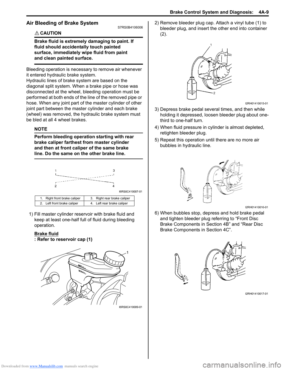
Bleeding operation is necessary to remove air whenever
it entered hydraulic brake system.
Hydraulic lines of brake system are based on the
diagonal split system. When a brake pipe or hose was
disconnected at the wheel, bleeding operation must be
performed at both ends of the line of the removed pipe or
hose. When any joint part of the master cylinder of other
joint part between the master cylinder and each brake
(wheel) was removed, the hydraulic brake system must
be bled at all 4 wheel brakes.
NOTE
Perform bleeding operation starting with rear
brake caliper farthest from master cylinder
and then at front caliper of the same brake
line. Do the same on the other brake line.
1) Fill master cylinder rese rvoir with brake fluid and
keep at least one-half full of fluid during bleeding
operation.
Brake fluid
: Refer to reservoir cap (1) 2) Remove bleeder plug cap. Attach a vinyl tube (1) to
bleeder plug, and insert the other end into container
(2).
3) Depress brake pedal several times, and then while holding it depressed, loosen bleeder plug about one-
third to one-half turn.
4) When fluid pressure in cy linder is almost depleted,
retighten bleeder plug.
5) Repeat this operation until there are no more air bubbles in hydraulic line.
6) When bubbles stop, depress and hold brake pedal and tighten bleeder plug referring to “Front Disc
Brake Components in Section 4B” and “Rear Disc
Brake Components in Section 4C”.
1. Right front brake caliper 3. Right rear brake caliper
2. Left front brake caliper 4. Left rear brake caliper
I6RS0C410007-01
1
I6RS0C410009-01
I2RH01410015-01
I2RH01410016-01
I2RH01410017-01
Page 508 of 1496
Downloaded from www.Manualslib.com manuals search engine 4A-10 Brake Control System and Diagnosis:
7) Then attach bleeder plug cap.
8) After completing bleeding operation, apply fluid pressure to pipe line and check for leakage.
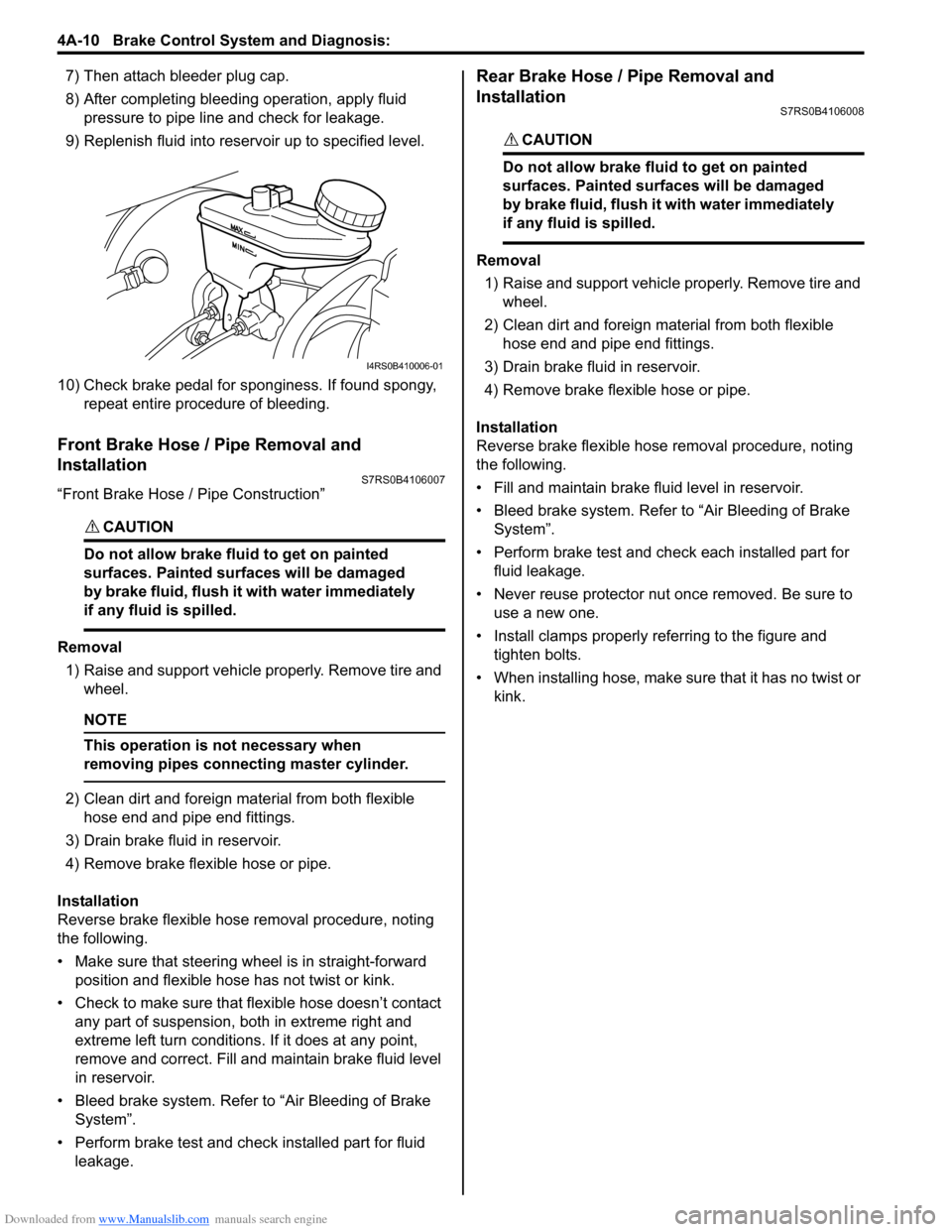
9) Replenish fluid into reserv oir up to specified level.
10) Check brake pedal for sponginess. If found spongy, repeat entire procedure of bleeding.
Front Brake Hose / Pipe Removal and
Installation
S7RS0B4106007
“Front Brake Hose / Pipe Construction”
CAUTION!
Do not allow brake fluid to get on painted
surfaces. Painted surfaces will be damaged
by brake fluid, flush it with water immediately
if any fluid is spilled.
Removal
1) Raise and support vehicle properly. Remove tire and wheel.
NOTE
This operation is not necessary when
removing pipes connecting master cylinder.
2) Clean dirt and foreign mate rial from both flexible
hose end and pipe end fittings.
3) Drain brake fluid in reservoir.
4) Remove brake flexible hose or pipe.
Installation
Reverse brake flexible hose removal procedure, noting
the following.
• Make sure that steering wh eel is in straight-forward
position and flexible hose has not twist or kink.
• Check to make sure that flexible hose doesn’t contact any part of suspension, both in extreme right and
extreme left turn conditions. If it does at any point,
remove and correct. Fill and maintain brake fluid level
in reservoir.
• Bleed brake system. Refer to “Air Bleeding of Brake System”.
• Perform brake test and check installed part for fluid leakage.
Rear Brake Hose / Pipe Removal and
Installation
S7RS0B4106008
CAUTION!
Do not allow brake fluid to get on painted
surfaces. Painted surfaces will be damaged
by brake fluid, flush it with water immediately
if any fluid is spilled.
Removal
1) Raise and support vehicle properly. Remove tire and wheel.
2) Clean dirt and foreign material from both flexible hose end and pipe end fittings.
3) Drain brake fluid in reservoir.
4) Remove brake flexible hose or pipe.
Installation
Reverse brake flexible hose removal procedure, noting
the following.
• Fill and maintain brake fluid level in reservoir.
• Bleed brake system. Refer to “Air Bleeding of Brake System”.
• Perform brake test and check each installed part for fluid leakage.
• Never reuse protector nut once removed. Be sure to use a new one.
• Install clamps properly referring to the figure and tighten bolts.
• When installing hose, make sure that it has no twist or
kink.
I4RS0B410006-01
Page 521 of 1496
Downloaded from www.Manualslib.com manuals search engine Front Brakes: 4B-5
Assembly
Assemble parts in reverse order of disassembly,
observing the following instructions.
CAUTION!
• Wash each part cleanly before installation in the same fluid as the one used in master
cylinder reservoir.
• Never use other fluid or thinner.
• Before installing piston seal or cylinder boot to cylinder, apply brake fluid to them.
• Install a new piston seal into groove in cylinder securely making sure that it is not
twisted.
• Before installing caliper to carrier, check for slid pin smooth movement in thrust
direction.
• After reassembling brake lines, bleed air from them.
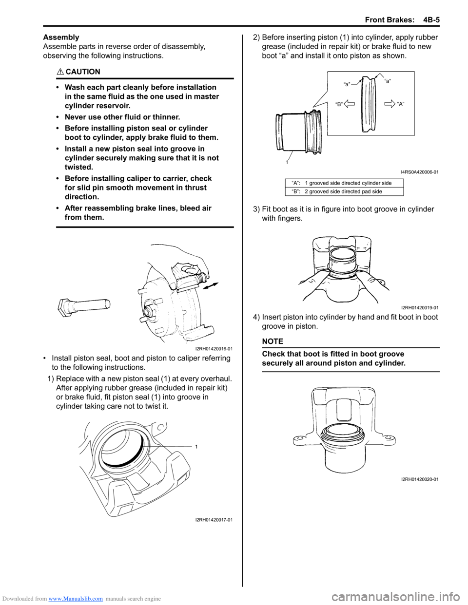
• Install piston seal, boot and piston to caliper referring to the following instructions.
1) Replace with a new piston seal (1) at every overhaul. After applying rubber grease (included in repair kit)
or brake fluid, fit piston seal (1) into groove in
cylinder taking care not to twist it. 2) Before inserting piston (1) into cylinder, apply rubber
grease (included in repair kit) or brake fluid to new
boot “a” and install it onto piston as shown.
3) Fit boot as it is in figure into boot groove in cylinder with fingers.
4) Insert piston into cylinder by hand and fit boot in boot groove in piston.
NOTE
Check that boot is fitted in boot groove
securely all around piston and cylinder.
I2RH01420016-01
1
I2RH01420017-01
“A”: 1 grooved side directed cylinder side
“B”: 2 grooved side directed pad side
I4RS0A420006-01
I2RH01420019-01
I2RH01420020-01
Page 522 of 1496
Downloaded from www.Manualslib.com manuals search engine 4B-6 Front Brakes:
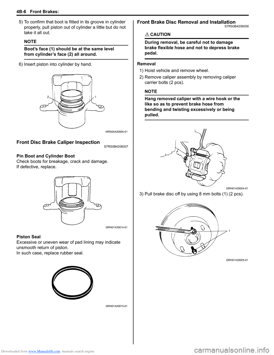
5) To confirm that boot is fitted in its groove in cylinder
properly, pull piston out of cylinder a little but do not
take it all out.
NOTE
Boot’s face (1) should be at the same level
from cylinder’s face (2) all around.
6) Insert piston into cylinder by hand.
Front Disc Brake Caliper InspectionS7RS0B4206007
Pin Boot and Cylinder Boot
Check boots for breakage, crack and damage.
If defective, replace.
Piston Seal
Excessive or uneven wear of pad lining may indicate
unsmooth return of piston.
In such case, replace rubber seal.
Front Brake Disc Removal and InstallationS7RS0B4206008
CAUTION!
During removal, be care ful not to damage
brake flexible hose and not to depress brake
pedal.
Removal
1) Hoist vehicle and remove wheel.
2) Remove caliper assembly by removing caliper carrier bolts (2 pcs).
NOTE
Hang removed caliper with a wire hook or the
like so as to prevent brake hose from
bending and twisting excessively or being
pulled.
3) Pull brake disc off by using 8 mm bolts (1) (2 pcs).
I4RS0A420004-01
I2RH01420014-01
I2RH01420015-01
I2RH01420024-01
I2RH01420025-01