sdm SUZUKI SWIFT 2006 2.G Service Workshop Manual
[x] Cancel search | Manufacturer: SUZUKI, Model Year: 2006, Model line: SWIFT, Model: SUZUKI SWIFT 2006 2.GPages: 1496, PDF Size: 34.44 MB
Page 1246 of 1496
Downloaded from www.Manualslib.com manuals search engine 9A-75 Wiring Systems:
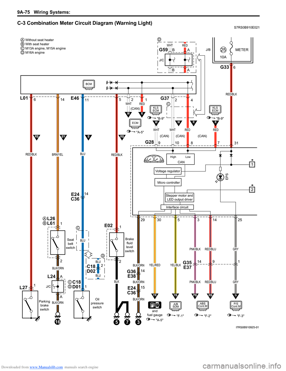
C-3 Combination Meter Circuit Diagram (Warning Light)S7RS0B910E021
J/BMETER
10A25
G2831
3
E24
C3615
G36 E3814
Stepper motor and
LED output driver
Voltage regulator
Interface circuit
Micro controllerEPS
G336
RED/BLK
145293025
PNK/BLKGRY
GRY
RED/BLU
PNK/BLK
BLK/ORN
BLK/ORN
BLK/ORN
RED/BLU
P/S
Cont M
"F-3"
RBPBYBYR
YEL/BLKYEL/RED
A/B
SDM
"F-1""A-5"
ABS
Cont.M
"F-2"
G
CAN
High Low
WHTWHTRED
WHTRED
RED
RW
109 8
6L0114
RED/BLKBRN/YEL
L271
Parking
brake
switch
1
2
A
A
16
BLK/ORN
BLK/ORN
J/C
L24
Seat belt
switch
Oil
pressure switch
E24
C3614
BLU
BLU
1C18
D01
RED/BLK
E021
Brake
fluid
level
switch
and
fuel gauge
2
53
BLK
11 5E46G372
4
RW
W
21WHTRED
"A-5"
1
2
RBBBYRB
7
BCM
ECM"B-9"
KLS
ECM
7
R"B-9"
KLS
ECM
Without seat heater
AWith seat heater
BM13A engine, M15A engine
CM16A engine
D
C
C
C
D
(CAN)
(CAN) (CAN)
(CAN)
L26
L61AB
B
BA
A
J/C
G59
BLU
BLU
D
C18
D022G35 E371419
D
I7RS0B910925-01
Page 1264 of 1496
Downloaded from www.Manualslib.com manuals search engine 9A-93 Wiring Systems:
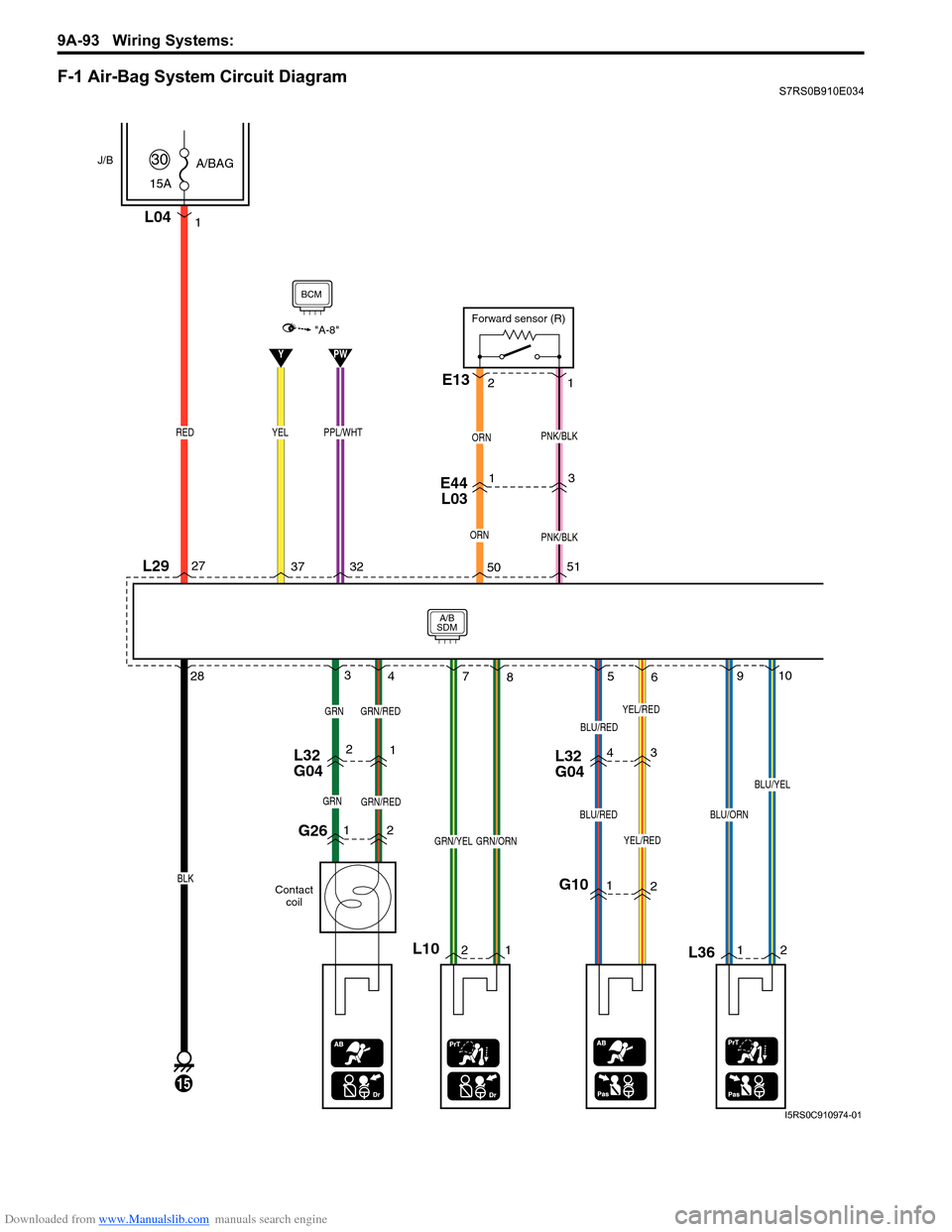
F-1 Air-Bag System Circuit DiagramS7RS0B910E034
3
ORN
YPW
A/B
SDM
L29
J/B
15A A/BAG
30
RED
L04
BCM
15
BLK
1
E44
L031
PNK/BLK
E13
Forward sensor (R)
1
2
Contact
coil
G2612
L32
G0421
L1021
YEL/RED
GRN/RED
G101 2
43
YEL/RED
L3612
3
4 7
856910
28 27
37 32 5051
"A-8"
L32
G04
ORN
PNK/BLKYELPPL/WHT
GRN
GRNGRN/RED
GRN/YELGRN/ORN
BLU/RED
BLU/REDBLU/ORN
BLU/YEL
I5RS0C910974-01
Page 1265 of 1496

Downloaded from www.Manualslib.com manuals search engine Wiring Systems: 9A-94
L30
L25
L18 L411212
A/B
SDM
L29
L11L351
2
1
2
1235
1113
1420 192122
46
47
45
44
IF EQPD
Side-sensor Side-sensor
LT GRN/BLK
YEL/GRNBLK/YELBRN/YEL
Side curtain
Diagnosis
connector #3
Side air-bag Side air-bag Side curtain
L044
G3413
J/B
"C-3"
YB
2
YEL/BLK
YEL/BLK
WHT/REDWHT/GRNLT GRN
GRY/RED
PPL
GRY
12
BRN/WHTBRNYEL/BLU
12
1
L532
I7RS0B910947-01
Page 1299 of 1496
Downloaded from www.Manualslib.com manuals search engine Instrumentation / Driver Info. / Horn: 9C-4
Schematic and Routing Diagram
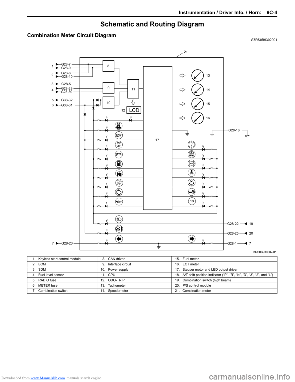
Combination Meter Circuit DiagramS7RS0B9302001
16
15
14
13
G28-5
5
6
3
G28-26
7
G28-2219
G28-2520
G28-17
12
10 11
21
9
17
G28-304G28-29
18
G28-16
G28-9
G28-10G28-8 G28-7
1
2 8
G38-31
G38-32
I7RS0B930002-01
1. Keyless start control module
8. CAN driver 15. Fuel meter
2. BCM 9. Interface circuit 16. ECT meter
3. SDM 10. Power supply 17. Stepper motor and LED output driver
4. Fuel level sensor 11. CPU 18. A/T shift position indicator (“P”, “R”, “N”, “D”, “3”, “2”, and “L”)
5. RADIO fuse 12. ODO-TRIP 19. Combination switch (high beam)
6. METER fuse 13. Tachometer 20. P/S control module
7. Combination switch 14. Speedometer 21. Combination meter
Page 1300 of 1496
Downloaded from www.Manualslib.com manuals search engine 9C-5 Instrumentation / Driver Info. / Horn:
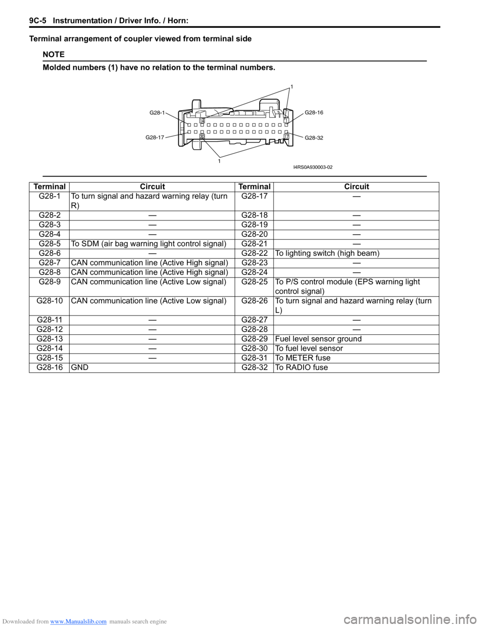
Terminal arrangement of coupler viewed from terminal side
NOTE
Molded numbers (1) have no relation to the terminal numbers.
TerminalCircuitTerminal Circuit
G28-1 To turn signal and hazard warning relay (turn R) G28-17
—
G28-2 —G28-18 —
G28-3 —G28-19 —
G28-4 —G28-20 —
G28-5 To SDM (air bag warning light control signal) G28-21 —
G28-6 —G28-22 To lighting switch (high beam)
G28-7 CAN communication line (Active High signal) G28-23 —
G28-8 CAN communication line (Active High signal) G28-24 —
G28-9 CAN communication line (Active Low signal) G 28-25 To P/S control module (EPS warning light
control signal)
G28-10 CAN communication line (Active Low signal) G28-26 To turn signal and hazard warning relay (turn L)
G28-11 —G28-27 —
G28-12 —G28-28 —
G28-13 —G28-29 Fuel level sensor ground
G28-14 —G28-30 To fuel level sensor
G28-15 —G28-31 To METER fuse
G28-16 GND G28-32 To RADIO fuse
G28-1 G28-16
G28-32
G28-17
1 1I4RS0A930003-02
Page 1409 of 1496
![SUZUKI SWIFT 2006 2.G Service Workshop Manual Downloaded from www.Manualslib.com manuals search engine Body Electrical Control System: 10B-6
[A]: Vehicle not equipped with diagnosis connector 19. Door key cylinder switch (included in door lock a SUZUKI SWIFT 2006 2.G Service Workshop Manual Downloaded from www.Manualslib.com manuals search engine Body Electrical Control System: 10B-6
[A]: Vehicle not equipped with diagnosis connector 19. Door key cylinder switch (included in door lock a](/img/20/7607/w960_7607-1408.png)
Downloaded from www.Manualslib.com manuals search engine Body Electrical Control System: 10B-6
[A]: Vehicle not equipped with diagnosis connector 19. Door key cylinder switch (included in door lock actuator)40. SDM
[B]: Vehicle equipped with diagnosis conn ector 20. Manual door lock switch 41. Rear end door window defogger relay
[C]: ESP ® model 21. Rear end door window defogger switch 42. Rear end door window defogger
1. BCM (included in junction block assembly) 22. Rear end door opener switch 43. Rear end door window defogger indicator lamp
2. Rear washer motor 23. “3” position switch (A/T model)44. Horn relay
3. Rear wiper motor 24. A/C switch45. Horn switch
4. Rear wiper relay 25. Rear end door opener relay46. Horn
5. Rear wiper and washer switch 26. Rear end door opener actuator47. Lighting switch
6. Outside air temperature sensor 27. TCM (A/T model)48. Ignition switch
7. Key reminder switch 28. ECM49. Battery
8. Theft deterrent light 29. Combination meter50. To turn signal light
9. Oil pressure switch 30. Data link connector (DLC)51. Body ground
10. Generator 31. To ECM, ABS/ESP®, P/S control module 52. Engine ground
11. Information display (if equipped) 32. To SDM53. Keyless start control module (if equipped)
12. Keyless entry receiver (if equipped) 33. Door lock actuator relay 54. Right side door mirror heater (if equipped)
13. Driver side door switch 34. Driver side door lock actuator55. Left side door mirror heater (if equipped)
14. Other than driver side door switch 35. Passenger side door lock actuator56. ABS/ESP® control module
15. Rear end door switch 36. Rear door lock actuator57. To HVAC control module
16. Driver side seat belt switch 37. Turn signal and hazard warning relay 58. CAN junction connector
17. Brake fluid level switch 38. Hazard warning switch59. Steering angle sensor
18. Parking brake switch 39. Interior light
Page 1422 of 1496
Downloaded from www.Manualslib.com manuals search engine 10B-19 Body Electrical Control System:
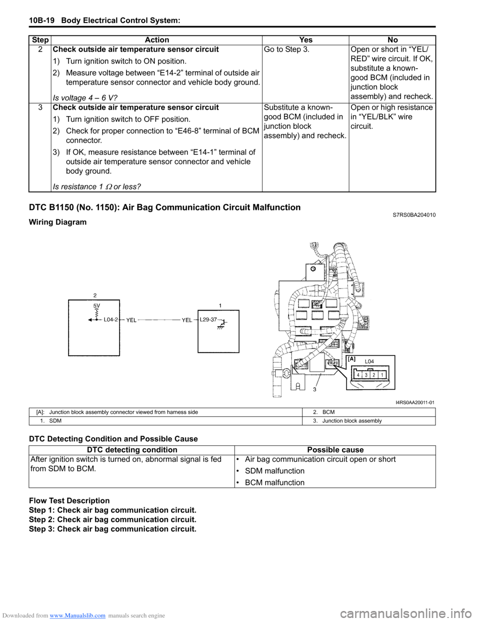
DTC B1150 (No. 1150): Air Bag Communication Circuit MalfunctionS7RS0BA204010
Wiring Diagram
DTC Detecting Condition and Possible Cause
Flow Test Description
Step 1: Check air bag communication circuit.
Step 2: Check air bag communication circuit.
Step 3: Check air bag communication circuit. 2
Check outside air temperature sensor circuit
1) Turn ignition switch to ON position.
2) Measure voltage between “E14-2” terminal of outside air
temperature sensor connector and vehicle body ground.
Is voltage 4 – 6 V? Go to Step 3. Open or short in “YEL/
RED” wire circuit. If OK,
substitute a known-
good BCM (included in
junction block
assembly) and recheck.
3 Check outside air temperature sensor circuit
1) Turn ignition switch to OFF position.
2) Check for proper connection to “E46-8” terminal of BCM
connector.
3) If OK, measure resistance between “E14-1” terminal of outside air temperature sens or connector and vehicle
body ground.
Is resistance 1
Ω or less? Substitute a known-
good BCM (included in
junction block
assembly) and recheck.
Open or high resistance
in “YEL/BLK” wire
circuit.
Step Action Yes No
I4RS0AA20011-01
[A]: Junction block assembly connect
or viewed from harness side 2. BCM
1. SDM 3. Junction block assembly
DTC detecting conditionPossible cause
After ignition switch is turned on, abnormal signal is fed
from SDM to BCM. • Air bag communication circuit open or short
• SDM malfunction
• BCM malfunction
Page 1423 of 1496
Downloaded from www.Manualslib.com manuals search engine Body Electrical Control System: 10B-20
DTC Troubleshooting
DTC B1157 (No. 1157): Air Bag Deployment Signal InputS7RS0BA204011
Wiring Diagram
Refer to “DTC B1150 (No. 1150): Air Bag Communication Circuit Malfunction”.
DTC Detecting Conditi on and Possible Cause
Flow Test Description
Step 1: Check DTC for SDM.
DTC Troubleshooting Step Action Yes No
1 Check air bag communication circuit
1) Turn ignition switch to OFF position.
2) Disconnect connector from SDM referring to “SDM
Removal and Installation in Section 8B”.
3) Disconnect connector from junction block assembly.
4) Turn ignition switch to ON position.
5) Measure voltage between “L29-37” terminal of SDM connector and vehicle body ground.
Is voltage 0 V? Go to Step 2. Short to power supply in
air bag communication
circuit.
2 Check air bag communication circuit
1) Turn ignition switch to OFF position.
2) Connect connectors to junction block assembly.
3) Turn ignition switch to ON position.
4) Measure voltage between “L04-2” terminal of junction
block assembly connector and vehicle body ground.
Is voltage 4 – 6 V? Go to Step 3.
Short to ground in air
bag communication
circuit. If OK, substitute
a known-good BCM
(included in junction
block assembly) and
recheck.
3 Check air bag communication circuit
1) Measure voltage between “L29-37” terminal of SDM
connector and vehicle body ground.
Is voltage 4 – 6 V? Substitute a known-
good SDM and recheck.
Open or high resistance
in air bag
communication circuit.
DTC detecting condition
Possible cause
Air bag deployment signal is fed from SDM to BCM. • Air bag component parts
• BCM malfunction
StepAction YesNo
1 DTC check of SDM
1) Check DTC stored in SDM re ferring to “DTC Check in
Section 8B”.
Is DTC B1021 detected? Go to “DTC B1021:
Front Air Bag Module
Deployed in Section
8B”.
Substitute a known-
good BCM (included in
junction block
assembly) and recheck.
Page 1437 of 1496
Downloaded from www.Manualslib.com manuals search engine Body Electrical Control System: 10B-34
Junction block connector “E40”
Junction block connector “E41”
Junction block connector “G32”
Junction block connector “G33”
Junction block connector “G34”
Junction block connector “K01”
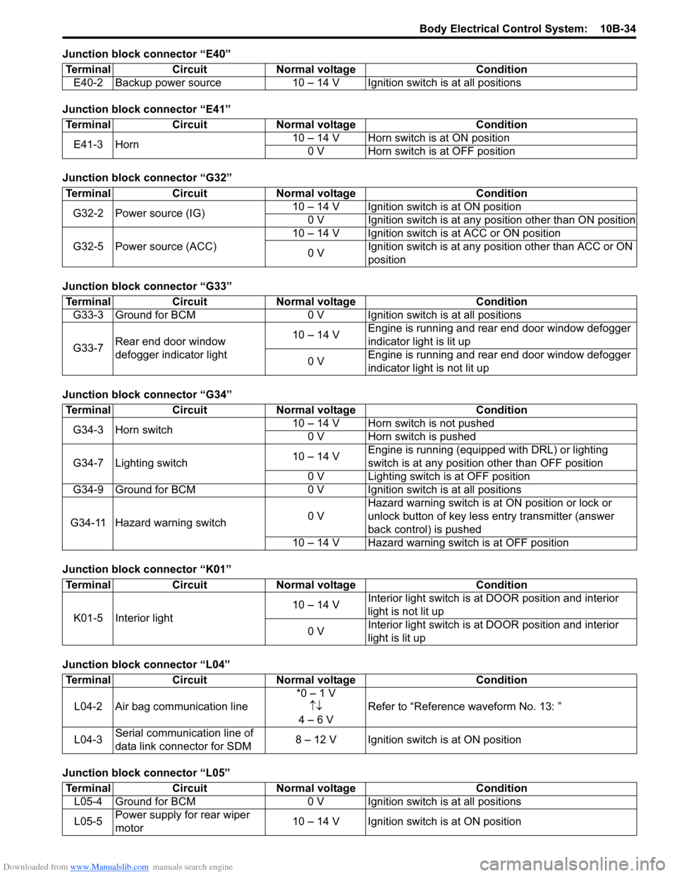
Junction block connector “L04”
Junction block connector “L05”Terminal Circuit Normal voltage Condition
E40-2 Backup power source 10 – 14 V Igni tion switch is at all positions
TerminalCircuitNormal voltage Condition
E41-3 Horn 10 – 14 V Horn switch is at ON position
0 V Horn switch is at OFF position
Terminal CircuitNormal voltage Condition
G32-2 Power source (IG) 10 – 14 V Ignition switch is at ON position
0 V Ignition switch is at any position other than ON position
G32-5 Power source (ACC) 10 – 14 V Ignition switch is at ACC or ON position
0 V Ignition switch is at any position other than ACC or ON
position
Terminal
CircuitNormal voltage Condition
G33-3 Ground for BCM 0 V Ignition switch is at all positions
G33-7 Rear end door window
defogger indicator light 10 – 14 V
Engine is running and rear end door window defogger
indicator light is lit up
0 V Engine is running and rear end door window defogger
indicator light is not lit up
Terminal
CircuitNormal voltage Condition
G34-3 Horn switch 10 – 14 V Horn switch is not pushed
0 V Horn switch is pushed
G34-7 Lighting switch 10 – 14 VEngine is running (equipped with DRL) or lighting
switch is at any position other than OFF position
0 V Lighting switch is at OFF position
G34-9 Ground for BCM 0 V Ignition switch is at all positions
G34-11 Hazard warning switch 0 VHazard warning switch is at
ON position or lock or
unlock button of key less entry transmitter (answer
back control) is pushed
10 – 14 V Hazard warning switch is at OFF position
Terminal CircuitNormal voltage Condition
K01-5 Interior light 10 – 14 V
Interior light switch is at
DOOR position and interior
light is not lit up
0 V Interior light switch is at
DOOR position and interior
light is lit up
Terminal CircuitNormal voltage Condition
L04-2 Air bag communication line *0 – 1 V
↑↓
4 – 6 V Refer to “Reference
waveform No. 13: ”
L04-3 Serial communication line of
data link connector for SDM 8 – 12 V Ignition switch is at ON position
Terminal
CircuitNormal voltage Condition
L05-4 Ground for BCM 0 V Ignition switch is at all positions
L05-5 Power supply for rear wiper
motor 10 – 14 V Ignition switch is at ON position
Page 1441 of 1496
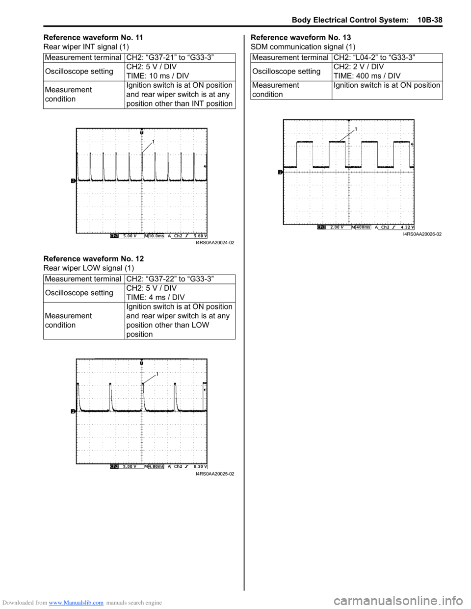
Downloaded from www.Manualslib.com manuals search engine Body Electrical Control System: 10B-38
Reference waveform No. 11
Rear wiper INT signal (1)
Reference waveform No. 12
Rear wiper LOW signal (1)Reference waveform No. 13
SDM communication signal (1)
Measurement terminal CH2: “G37-21” to “G33-3”
Oscilloscope setting CH2: 5 V / DIV
TIME: 10 ms / DIV
Measurement
condition Ignition switch is at ON position
and rear wiper switch is at any
position other than INT position
Measurement terminal CH2: “G37-22” to “G33-3”
Oscilloscope setting CH2: 5 V / DIV
TIME: 4 ms / DIV
Measurement
condition Ignition switch is at ON position
and rear wiper switch is at any
position other than LOW
position
I4RS0AA20024-02
I4RS0AA20025-02
Measurement terminal CH2: “L04-2” to “G33-3”
Oscilloscope setting
CH2: 2 V / DIV
TIME: 400 ms / DIV
Measurement
condition Ignition switch is at ON position
I4RS0AA20026-02