SUZUKI SWIFT 2006 2.G Service Workshop Manual
[x] Cancel search | Manufacturer: SUZUKI, Model Year: 2006, Model line: SWIFT, Model: SUZUKI SWIFT 2006 2.GPages: 1496, PDF Size: 34.44 MB
Page 131 of 1496
Downloaded from www.Manualslib.com manuals search engine Engine General Information and Diagnosis: 1A-81
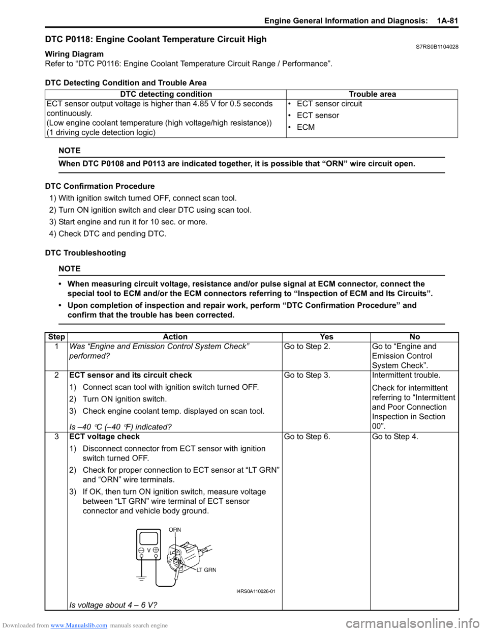
DTC P0118: Engine Coolant Temperature Circuit HighS7RS0B1104028
Wiring Diagram
Refer to “DTC P0116: Engine Coolant Temperature Circuit Range / Performance”.
DTC Detecting Condition and Trouble Area
NOTE
When DTC P0108 and P0113 are indicated together, it is possible that “ORN” wire circuit open.
DTC Confirmation Procedure
1) With ignition switch turned OFF, connect scan tool.
2) Turn ON ignition switch and clear DTC using scan tool.
3) Start engine and run it for 10 sec. or more.
4) Check DTC and pending DTC.
DTC Troubleshooting
NOTE
• When measuring circuit voltage, resistance and/ or pulse signal at ECM connector, connect the
special tool to ECM and/or the ECM connectors re ferring to “Inspection of ECM and Its Circuits”.
• Upon completion of inspection and repair work, perform “DTC Confirmation Procedure” and confirm that the trouble has been corrected.
DTC detecting condition Trouble area
ECT sensor output voltage is higher than 4.85 V for 0.5 seconds
continuously.
(Low engine coolant temperature (high voltage/high resistance))
(1 driving cycle detection logic) • ECT sensor circuit
• ECT sensor
•ECM
Step
Action YesNo
1 Was “Engine and Emission Control System Check”
performed? Go to Step 2.
Go to “Engine and
Emission Control
System Check”.
2 ECT sensor and its circuit check
1) Connect scan tool with i gnition switch turned OFF.
2) Turn ON ignition switch.
3) Check engine coolant temp. displayed on scan tool.
Is –40
°C (–40 °F) indicated? Go to Step 3. Intermittent trouble.
Check for intermittent
referring to “Intermittent
and Poor Connection
Inspection in Section
00”.
3 ECT voltage check
1) Disconnect connector from ECT sensor with ignition
switch turned OFF.
2) Check for proper connection to ECT sensor at “LT GRN” and “ORN” wire terminals.
3) If OK, then turn ON igniti on switch, measure voltage
between “LT GRN” wire terminal of ECT sensor
connector and vehicle body ground.
Is voltage about 4 – 6 V? Go to Step 6. Go to Step 4.
I4RS0A110026-01
Page 132 of 1496
Downloaded from www.Manualslib.com manuals search engine 1A-82 Engine General Information and Diagnosis:
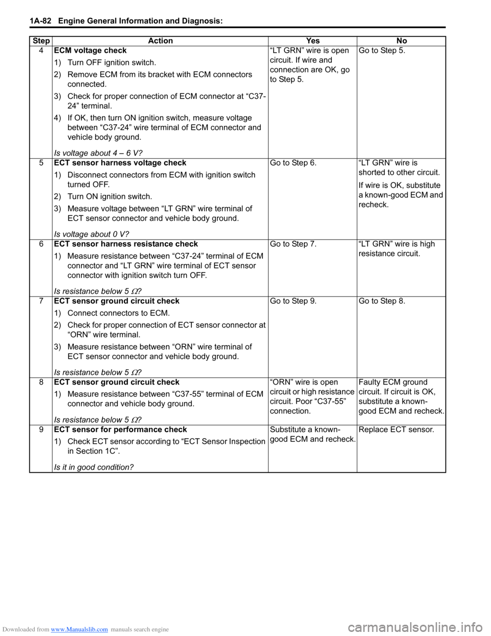
4ECM voltage check
1) Turn OFF ignition switch.
2) Remove ECM from its br acket with ECM connectors
connected.
3) Check for proper connection of ECM connector at “C37- 24” terminal.
4) If OK, then turn ON igniti on switch, measure voltage
between “C37-24” wire terminal of ECM connector and
vehicle body ground.
Is voltage about 4 – 6 V? “LT GRN” wire is open
circuit. If wire and
connection are OK, go
to Step 5.
Go to Step 5.
5 ECT sensor harness voltage check
1) Disconnect connectors from ECM with ignition switch
turned OFF.
2) Turn ON ignition switch.
3) Measure voltage between “LT GRN” wire terminal of ECT sensor connector and vehicle body ground.
Is voltage about 0 V? Go to Step 6. “LT GRN” wire is
shorted to other circuit.
If wire is OK, substitute
a known-good ECM and
recheck.
6 ECT sensor harness resistance check
1) Measure resistance between “C37-24” terminal of ECM
connector and “LT GRN” wire terminal of ECT sensor
connector with ignition switch turn OFF.
Is resistance below 5
Ω? Go to Step 7. “LT GRN” wire is high
resistance circuit.
7 ECT sensor ground circuit check
1) Connect connectors to ECM.
2) Check for proper connection of ECT sensor connector at
“ORN” wire terminal.
3) Measure resistance between “ORN” wire terminal of ECT sensor connector and vehicle body ground.
Is resistance below 5
Ω? Go to Step 9. Go to Step 8.
8 ECT sensor ground circuit check
1) Measure resistance between “C37-55” terminal of ECM
connector and vehicle body ground.
Is resistance below 5
Ω? “ORN” wire is open
circuit or high resistance
circuit. Poor “C37-55”
connection.
Faulty ECM ground
circuit. If circuit is OK,
substitute a known-
good ECM and recheck.
9 ECT sensor for performance check
1) Check ECT sensor according to “ECT Sensor Inspection
in Section 1C”.
Is it in good condition? Substitute a known-
good ECM and recheck.
Replace ECT sensor.
Step Action Yes No
Page 133 of 1496
Downloaded from www.Manualslib.com manuals search engine Engine General Information and Diagnosis: 1A-83
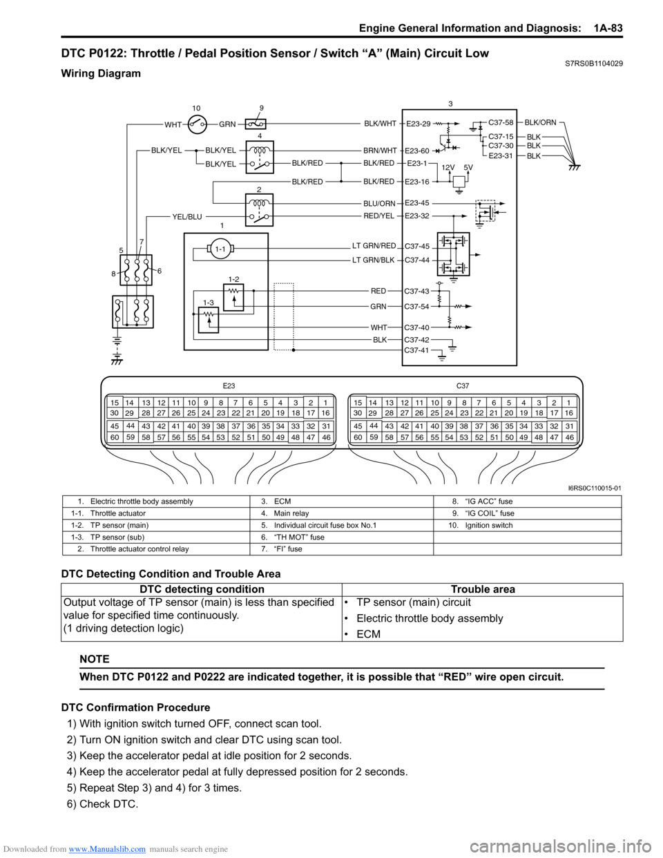
DTC P0122: Throttle / Pedal Position Sensor / Switch “A” (Main) Circuit LowS7RS0B1104029
Wiring Diagram
DTC Detecting Condition and Trouble Area
NOTE
When DTC P0122 and P0222 are indicated together, it is possible that “RED” wire open circuit.
DTC Confirmation Procedure
1) With ignition switch turned OFF, connect scan tool.
2) Turn ON ignition switch and clear DTC using scan tool.
3) Keep the accelerator pedal at idle position for 2 seconds.
4) Keep the accelerator pedal at fully depressed position for 2 seconds.
5) Repeat Step 3) and 4) for 3 times.
6) Check DTC.
E23 C37
34
1819
567
1011
17
20
47 46
495051
2122
52 16
25 9
24
14
29
55
57 54 53
59
60 58 2
262728
15
30
56 4832 31
34353637
40
42 39 38
44
45 43 41 331
1213
238
34
1819
567
1011
17
20
47 46
495051
2122
52 16
25 9
24
14
29
55
57 54 53
59
60 58 2
262728
15
30
56 4832 31
34353637
40
42 39 38
44
45 43 41 331
1213
238
12V
5VBLK/REDBLK/RED
BLK/YEL
12BLK/YEL
BLK/YEL
BRN/WHT
E23-1
E23-60
C37-58
C37-15 C37-30
BLK/ORN
BLKBLKE23-31 BLK
BLK/RED
BLU/ORN
RED/YELYEL/BLU
LT GRN/RED
LT GRN/BLK
RED
GRN
WHT
BLK
E23-16
E23-45
E23-32
C37-45
C37-44
C37-41C37-42
C37-40
C37-54
C37-43
1-1
1-2
1-3 3
4
5
8 67
10
9
E23-29 GRNBLK/WHTWHT
BLK/RED
I6RS0C110015-01
1. Electric throttle body assembly
3. ECM 8. “IG ACC” fuse
1-1. Throttle actuator 4. Main relay 9. “IG COIL” fuse
1-2. TP sensor (main) 5. Individual circuit fuse box No.110. Ignition switch
1-3. TP sensor (sub) 6. “TH MOT” fuse
2. Throttle actuator control relay 7. “FI” fuse
DTC detecting condition Trouble area
Output voltage of TP sensor (main) is less than specified
value for specified time continuously.
(1 driving detection logic) • TP sensor (main) circuit
• Electric throttle body assembly
•ECM
Page 134 of 1496
Downloaded from www.Manualslib.com manuals search engine 1A-84 Engine General Information and Diagnosis:
DTC Troubleshooting
NOTE
• When measuring circuit voltage, resistance and/or pulse signal at ECM connector, connect the
special tool to ECM and/or the ECM connectors re ferring to “Inspection of ECM and Its Circuits”.
• Upon completion of inspection and repair work, perform “DTC Confirmation Procedure” and confirm that the trouble has been corrected.
Step Action YesNo
1 Was “Engine and Emission Control System Check”
performed? Go to Step 2.
Go to “Engine and
Emission Control
System Check”.
2 TP sensor and its circuit check
1) Connect scan tool to DLC with ignition switch turned
OFF.
2) Turn ON ignition switch, check “TP Sensor 1 Volt” displayed on scan tool when accelerator pedal is idle
position and fully depressed.
Is displayed TP sensor value as described voltage in “Scan
Tool Data:”? Intermittent trouble.
Check for intermittent
referring to “Intermittent
and Poor Connection
Inspection in Section
00”.
Go to Step 3.
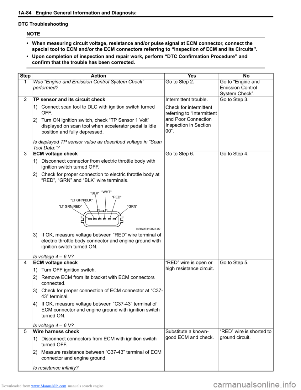
3 ECM voltage check
1) Disconnect connector from electric throttle body with
ignition switch turned OFF.
2) Check for proper connection to electric throttle body at “RED”, “GRN” and “BLK” wire terminals.
3) If OK, measure voltage between “RED” wire terminal of electric throttle body connector and engine ground with
ignition switch turned ON.
Is voltage 4 – 6 V? Go to Step 6.
Go to Step 4.
4 ECM voltage check
1) Turn OFF ignition switch.
2) Remove ECM from its br acket with ECM connectors
connected.
3) Check for proper connection of ECM connector at “C37- 43” terminal.
4) If OK, measure voltage between “C37-43” terminal of ECM connector and engine ground with ignition switch
turned ON.
Is voltage 4 – 6 V? “RED” wire is open or
high resistance circuit.
Go to Step 5.
5 Wire harness check
1) Disconnect connectors from ECM with ignition switch
turned OFF.
2) Measure resistance between “C37-43” terminal of ECM connector and engine ground.
Is resistance infinity? Substitute a known-
good ECM and check.
“RED” wire is shorted to
ground circuit.
"GRN"
"RED"
"WHT"
"BLK"
"LT GRN/BLK"
"LT GRN/RED"
I4RS0B110022-02
Page 135 of 1496
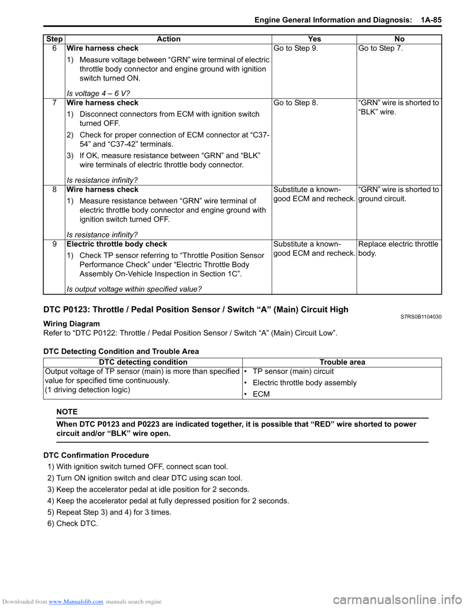
Downloaded from www.Manualslib.com manuals search engine Engine General Information and Diagnosis: 1A-85
DTC P0123: Throttle / Pedal Position Sensor / Switch “A” (Main) Circuit HighS7RS0B1104030
Wiring Diagram
Refer to “DTC P0122: Throttle / Pedal Position Sensor / Switch “A” (Main) Circuit Low”.
DTC Detecting Condition and Trouble Area
NOTE
When DTC P0123 and P0223 are indicated together, it is possible that “RED” wire shorted to power
circuit and/or “BLK” wire open.
DTC Confirmation Procedure
1) With ignition switch turned OFF, connect scan tool.
2) Turn ON ignition switch and clear DTC using scan tool.
3) Keep the accelerator pedal at idle position for 2 seconds.
4) Keep the accelerator pedal at fully depressed position for 2 seconds.
5) Repeat Step 3) and 4) for 3 times.
6) Check DTC. 6
Wire harness check
1) Measure voltage between “GRN” wire terminal of electric
throttle body connector and engine ground with ignition
switch turned ON.
Is voltage 4 – 6 V? Go to Step 9. Go to Step 7.
7 Wire harness check
1) Disconnect connectors from ECM with ignition switch
turned OFF.
2) Check for proper connection of ECM connector at “C37- 54” and “C37-42” terminals.
3) If OK, measure resistance between “GRN” and “BLK” wire terminals of electric throttle body connector.
Is resistance infinity? Go to Step 8. “GRN” wire is shorted to
“BLK” wire.
8 Wire harness check
1) Measure resistance between “GRN” wire terminal of
electric throttle body connector and engine ground with
ignition switch turned OFF.
Is resistance infinity? Substitute a known-
good ECM and recheck.
“GRN” wire is shorted to
ground circuit.
9 Electric throttle body check
1) Check TP sensor referring to “Throttle Position Sensor
Performance Check” under “Electric Throttle Body
Assembly On-Vehicle Inspection in Section 1C”.
Is output voltage within specified value? Substitute a known-
good ECM and recheck.
Replace electric throttle
body.
Step Action Yes No
DTC detecting condition
Trouble area
Output voltage of TP sensor (main) is more than specified
value for specified time continuously.
(1 driving detection logic) • TP sensor (main) circuit
• Electric throttle body assembly
•ECM
Page 136 of 1496
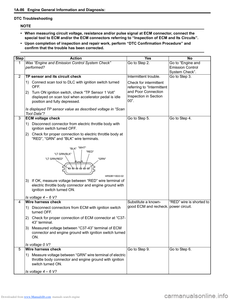
Downloaded from www.Manualslib.com manuals search engine 1A-86 Engine General Information and Diagnosis:
DTC Troubleshooting
NOTE
• When measuring circuit voltage, resistance and/or pulse signal at ECM connector, connect the
special tool to ECM and/or the ECM connectors re ferring to “Inspection of ECM and Its Circuits”.
• Upon completion of inspection and repair work, perform “DTC Confirmation Procedure” and confirm that the trouble has been corrected.
Step Action YesNo
1 Was “Engine and Emission Control System Check”
performed? Go to Step 2.
Go to “Engine and
Emission Control
System Check”.
2 TP sensor and its circuit check
1) Connect scan tool to DLC with ignition switch turned
OFF.
2) Turn ON ignition switch, check “TP Sensor 1 Volt” displayed on scan tool when accelerator pedal is idle
position and fully depressed.
Is displayed TP sensor value as described voltage in “Scan
To o l D a t a ” ? Intermittent trouble.
Check for intermittent
referring to “Intermittent
and Poor Connection
Inspection in Section
00”.
Go to Step 3.
3 ECM voltage check
1) Disconnect connector from electric throttle body with
ignition switch turned OFF.
2) Check for proper connection to electric throttle body at “RED”, “GRN” and “BLK” wire terminals.
3) If OK, measure voltage between “RED” wire terminal of electric throttle body connector and engine ground with
ignition switch turned ON.
Is voltage 4 – 6 V? Go to Step 5.
Go to Step 4.
4 Wire harness check
1) Disconnect connectors from ECM with ignition switch
turned OFF.
2) Check for proper connection of ECM connector at “C37- 43” terminal.
3) Measured voltage between “C37-43” terminal of ECM connector and engine ground with ignition switch turned
ON.
Is voltage 0 V? Substitute a known-
good ECM and recheck.
“RED” wire is shorted to
power circuit.
5 Wire harness check
1) Measure voltage between “GRN” wire terminal of electric
throttle body connector and engine ground with ignition
switch turned ON.
Is voltage 4 – 6 V? Go to Step 9.
Go to Step 6.
"GRN"
"RED"
"WHT"
"BLK"
"LT GRN/BLK"
"LT GRN/RED"
I4RS0B110022-02
Page 137 of 1496
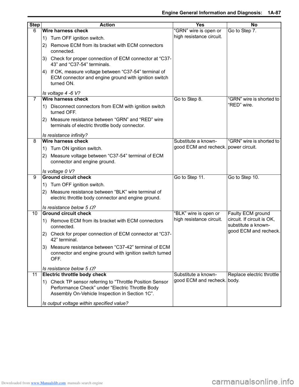
Downloaded from www.Manualslib.com manuals search engine Engine General Information and Diagnosis: 1A-87
6Wire harness check
1) Turn OFF ignition switch.
2) Remove ECM from its br acket with ECM connectors
connected.
3) Check for proper connection of ECM connector at “C37- 43” and “C37-54” terminals.
4) If OK, measure voltage between “C37-54” terminal of ECM connector and engine ground with ignition switch
turned ON.
Is voltage 4 -6 V? “GRN” wire is open or
high resistance circuit.
Go to Step 7.
7 Wire harness check
1) Disconnect connectors from ECM with ignition switch
turned OFF.
2) Measure resistance between “GRN” and “RED” wire terminals of electric th rottle body connector.
Is resistance infinity? Go to Step 8. “GRN” wire is shorted to
“RED” wire.
8 Wire harness check
1) Turn ON ignition switch.
2) Measure voltage between “C37-54” terminal of ECM
connector and engine ground.
Is voltage 0 V? Substitute a known-
good ECM and recheck.
“GRN” wire is shorted to
power circuit.
9 Ground circuit check
1) Turn OFF ignition switch.
2) Measure resistance between “BLK” wire terminal of
electric throttle body connector and engine ground.
Is resistance below 5
Ω? Go to Step 11. Go to Step 10.
10 Ground circuit check
1) Remove ECM from its br acket with ECM connectors
connected.
2) Check for proper connection of ECM connector at “C37- 42” terminal.
3) Measure resistance between “C37-42” terminal of ECM connector and engine ground with ignition switch turned
OFF.
Is resistance below 5
Ω? “BLK” wire is open or
high resistance circuit.
Faulty ECM ground
circuit. If circuit is OK,
substitute a known-
good ECM and recheck.
11 Electric throttle body check
1) Check TP sensor referring to “Throttle Position Sensor
Performance Check” under “Electric Throttle Body
Assembly On-Vehicle Inspection in Section 1C”.
Is output voltage within specified value? Substitute a known-
good ECM and recheck.
Replace electric throttle
body.
Step Action Yes No
Page 138 of 1496
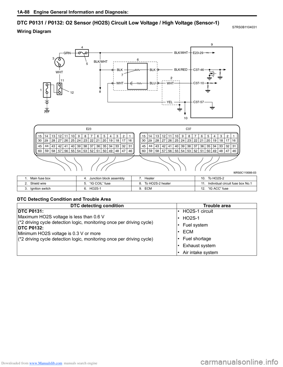
Downloaded from www.Manualslib.com manuals search engine 1A-88 Engine General Information and Diagnosis:
DTC P0131 / P0132: O2 Sensor (HO2S) Circuit Low Voltage / High Voltage (Sensor-1)S7RS0B1104031
Wiring Diagram
DTC Detecting Condition and Trouble Area
E23C37
34
1819
567
1011
17
20
47 46
495051
2122
52 16
25 9
24
14
29
55
57 54 53
59
60 58 2
262728
15
30
56 4832 31
34353637
40
42 39 38
44
45 43 41 331
1213
238
34
1819
567
1011
17
20
47 46
495051
2122
52 16
25 9
24
14
29
55
57 54 53
59
60 58 2
262728
15
30
56 4832 31
34353637
40
42 39 38
44
45 43 41 331
1213
238
BLK/WHT
WHT
11
GRN
3 9
E23-29
WHT
YEL
BLK/WHT
BLKC37-46
C37-10
C37-57
6
7
10
BLK
BLUWHT
BLK/RED
4
5
8
12
1
I6RS0C110006-03
1. Main fuse box
4. Junction block assembly 7. Heater 10. To HO2S-2
2. Shield wire 5. “IG COIL” fuse8. To HO2S-2 heater 11. Individual circuit fuse box No.1
3. Ignition switch 6. HO2S-19. ECM 12. “IG ACC” fuse
DTC detecting condition Trouble area
DTC P0131:
Maximum HO2S voltage is less than 0.6 V
(*2 driving cycle detection logic, monitoring once per driving cycle)
DTC P0132:
Minimum HO2S voltage is 0.3 V or more
(*2 driving cycle detection logic, monitoring once per driving cycle) • HO2S-1 circuit
•HO2S-1
• Fuel system
•ECM
• Fuel shortage
• Exhaust system
• Air intake system
Page 139 of 1496
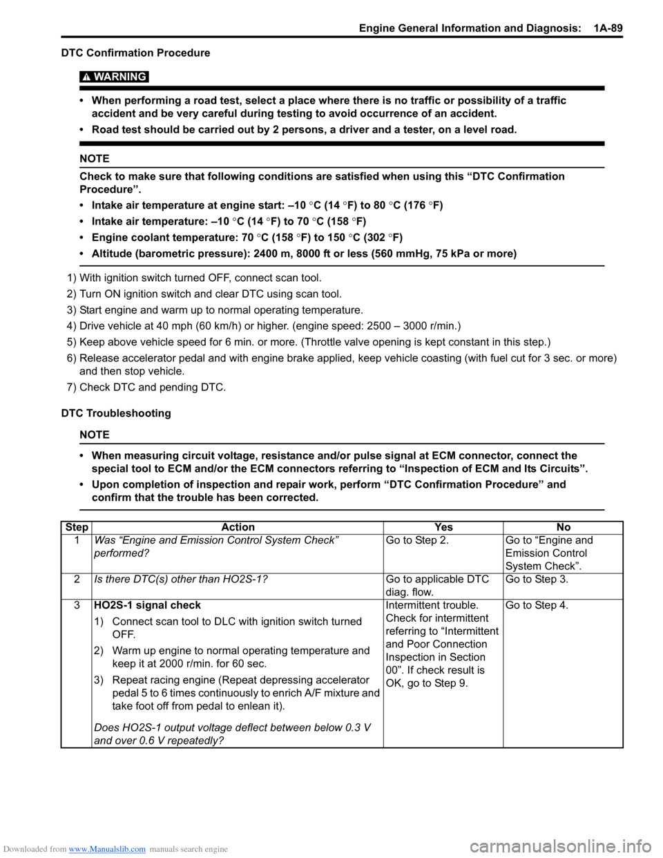
Downloaded from www.Manualslib.com manuals search engine Engine General Information and Diagnosis: 1A-89
DTC Confirmation Procedure
WARNING!
• When performing a road test, select a place where there is no traffic or possibility of a traffic accident and be very careful during testing to avoid occurrence of an accident.
• Road test should be carried out by 2 persons, a driver and a tester, on a level road.
NOTE
Check to make sure that following conditions ar e satisfied when using this “DTC Confirmation
Procedure”.
• Intake air temperature at engine start: –10 °C (14 ° F) to 80 °C (176 °F)
• Intake air temperature: –10 °C (14 °F) to 70 °C (158 °F)
• Engine coolant temperature: 70 °C (158 °F) to 150 °C (302 °F)
• Altitude (barometric pressure): 2400 m, 8000 ft or less (560 mmHg, 75 kPa or more)
1) With ignition switch turned OFF, connect scan tool.
2) Turn ON ignition switch and clear DTC using scan tool.
3) Start engine and warm up to normal operating temperature.
4) Drive vehicle at 40 mph (60 km/h) or higher. (engine speed: 2500 – 3000 r/min.)
5) Keep above vehicle speed for 6 min. or more. (Throt tle valve opening is kept constant in this step.)
6) Release accelerator pedal and with engine brake applied, keep vehicle coasting (with fuel cut for 3 sec. or more)
and then stop vehicle.
7) Check DTC and pending DTC.
DTC Troubleshooting
NOTE
• When measuring circuit voltage, resistance and/ or pulse signal at ECM connector, connect the
special tool to ECM and/or the ECM connectors re ferring to “Inspection of ECM and Its Circuits”.
• Upon completion of inspection and repair work, perform “DTC Confirmation Procedure” and confirm that the trouble has been corrected.
Step Action YesNo
1 Was “Engine and Emission Control System Check”
performed? Go to Step 2.
Go to “Engine and
Emission Control
System Check”.
2 Is there DTC(s) other than HO2S-1? Go to applicable DTC
diag. flow.Go to Step 3.
3 HO2S-1 signal check
1) Connect scan tool to DLC with ignition switch turned
OFF.
2) Warm up engine to normal operating temperature and keep it at 2000 r/min. for 60 sec.
3) Repeat racing engine (Repeat depressing accelerator pedal 5 to 6 times continuous ly to enrich A/F mixture and
take foot off from pedal to enlean it).
Does HO2S-1 output voltage deflect between below 0.3 V
and over 0.6 V repeatedly? Intermittent trouble.
Check for intermittent
referring to “Intermittent
and Poor Connection
Inspection in Section
00”. If check result is
OK, go to Step 9.
Go to Step 4.
Page 140 of 1496
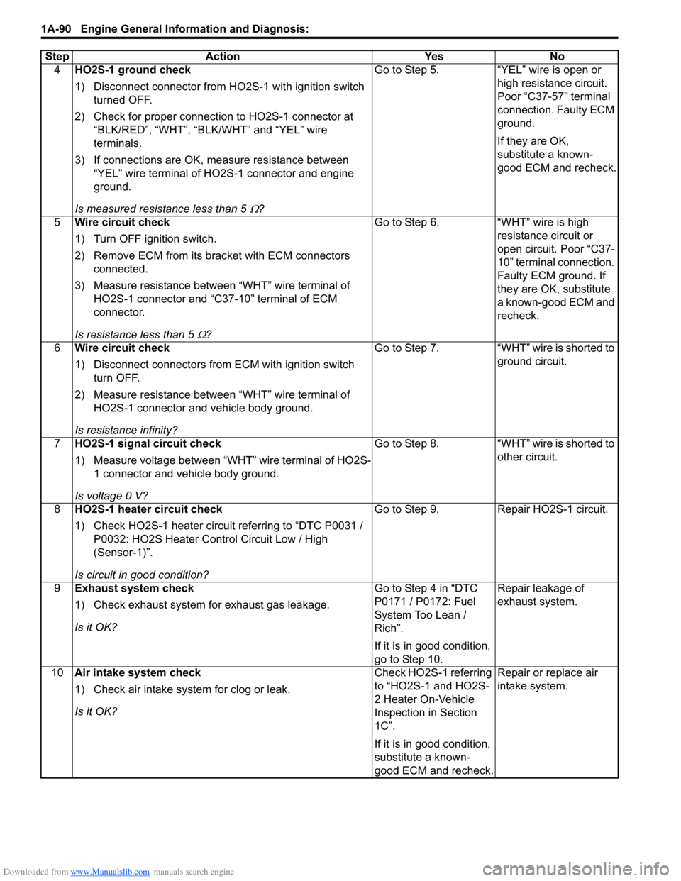
Downloaded from www.Manualslib.com manuals search engine 1A-90 Engine General Information and Diagnosis:
4HO2S-1 ground check
1) Disconnect connector from HO 2S-1 with ignition switch
turned OFF.
2) Check for proper connection to HO2S-1 connector at “BLK/RED”, “WHT”, “BLK /WHT” and “YEL” wire
terminals.
3) If connections are OK, m easure resistance between
“YEL” wire terminal of HO2S-1 connector and engine
ground.
Is measured resistance less than 5
Ω? Go to Step 5. “YEL” wire is open or
high resistance circuit.
Poor “C37-57” terminal
connection. Faulty ECM
ground.
If they are OK,
substitute a known-
good ECM and recheck.
5 Wire circuit check
1) Turn OFF ignition switch.
2) Remove ECM from its br acket with ECM connectors
connected.
3) Measure resistance between “WHT” wire terminal of HO2S-1 connector and “C37-10” terminal of ECM
connector.
Is resistance less than 5
Ω? Go to Step 6. “WHT” wire is high
resistance circuit or
open circuit. Poor “C37-
10” terminal connection.
Faulty ECM ground. If
they are OK, substitute
a known-good ECM and
recheck.
6 Wire circuit check
1) Disconnect connectors from ECM with ignition switch
turn OFF.
2) Measure resistance between “WHT” wire terminal of HO2S-1 connector and vehicle body ground.
Is resistance infinity? Go to Step 7. “WHT” wire is shorted to
ground circuit.
7 HO2S-1 signal circuit check
1) Measure voltage between “WHT” wire terminal of HO2S-
1 connector and vehicle body ground.
Is voltage 0 V? Go to Step 8. “WHT” wire is shorted to
other circuit.
8 HO2S-1 heater circuit check
1) Check HO2S-1 heater circuit referring to “DTC P0031 /
P0032: HO2S Heater Control Circuit Low / High
(Sensor-1)”.
Is circuit in good condition? Go to Step 9. Repair HO2S-1 circuit.
9 Exhaust system check
1) Check exhaust system for exhaust gas leakage.
Is it OK? Go to Step 4 in “DTC
P0171 / P0172: Fuel
System Too Lean /
Rich”.
If it is in good condition,
go to Step 10.Repair leakage of
exhaust system.
10 Air intake system check
1) Check air intake system for clog or leak.
Is it OK? Check HO2S-1 referring
to “HO2S-1 and HO2S-
2 Heater On-Vehicle
Inspection in Section
1C”.
If it is in good condition,
substitute a known-
good ECM and recheck.Repair or replace air
intake system.
Step Action Yes No