Clutch removal SUZUKI SWIFT 2006 2.G Service User Guide
[x] Cancel search | Manufacturer: SUZUKI, Model Year: 2006, Model line: SWIFT, Model: SUZUKI SWIFT 2006 2.GPages: 1496, PDF Size: 34.44 MB
Page 512 of 1496
Downloaded from www.Manualslib.com manuals search engine 4A-14 Brake Control System and Diagnosis:
6) Fill reservoir with specified fluid.
7) After completing the work, bleed air from brake and clutch system referring to “Air Bleeding of Brake
System” and “Air Bleeding of Clutch System in
Section 5C” (M/T model).
8) Install cowl top panel referring to “Cowl Top Components in Section 9K”.
9) Install windshield wiper referring to “Windshield
Wiper Removal and Insta llation in Section 9D”.
10) Perform brake test and check each installed part for fluid leakage.
Master Cylinder Assembly Disassembly and
Assembly
S7RS0B4106013
Disassembly
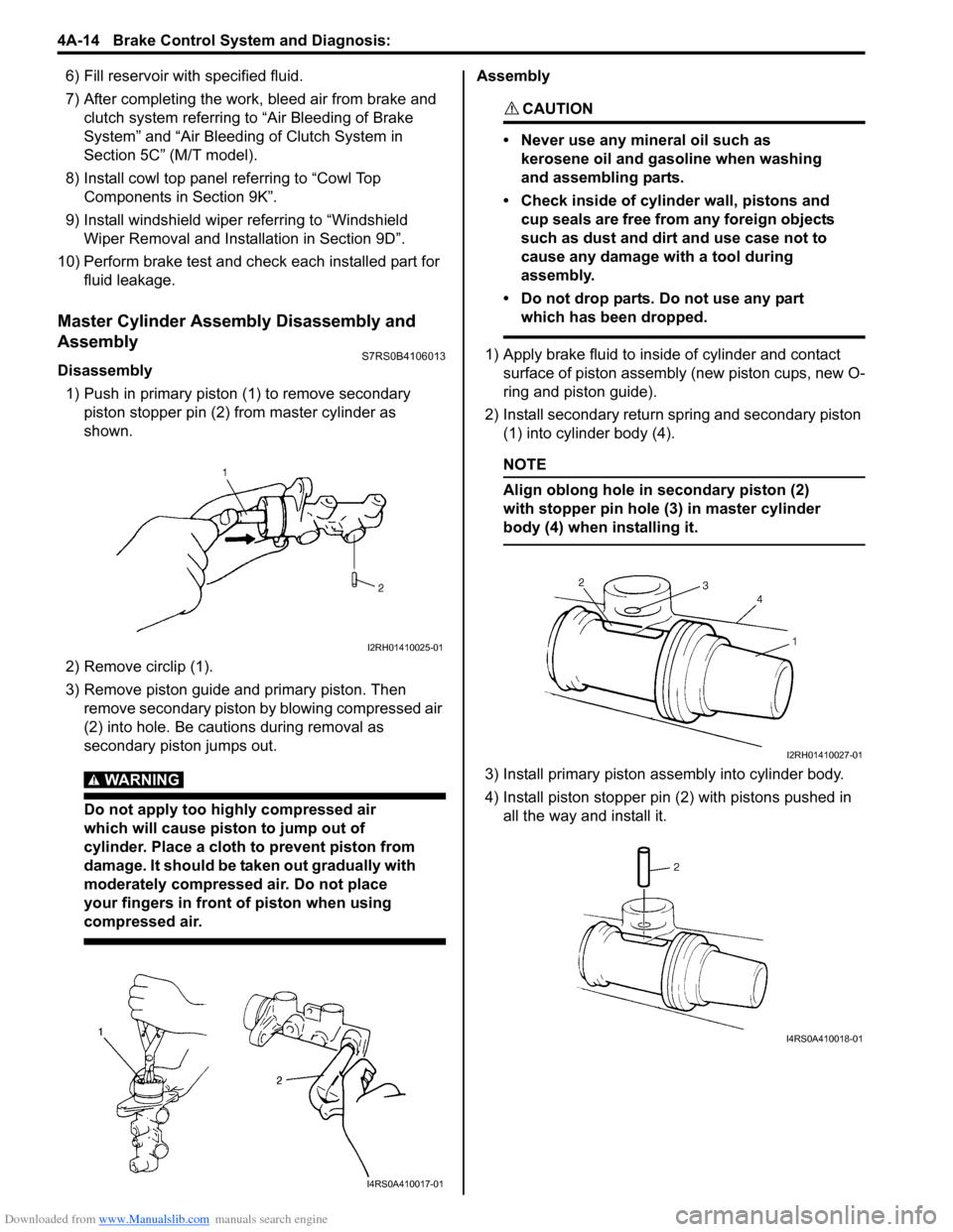
1) Push in primary piston (1) to remove secondary
piston stopper pin (2) from master cylinder as
shown.
2) Remove circlip (1).
3) Remove piston guide and primary piston. Then remove secondary piston by blowing compressed air
(2) into hole. Be cautions during removal as
secondary piston jumps out.
WARNING!
Do not apply too highly compressed air
which will cause piston to jump out of
cylinder. Place a cloth to prevent piston from
damage. It should be taken out gradually with
moderately compressed air. Do not place
your fingers in front of piston when using
compressed air.
Assembly
CAUTION!
• Never use any mineral oil such as kerosene oil and gasoline when washing
and assembling parts.
• Check inside of cylinder wall, pistons and cup seals are free from any foreign objects
such as dust and dirt and use case not to
cause any damage with a tool during
assembly.
• Do not drop parts. Do not use any part which has been dropped.
1) Apply brake fluid to inside of cylinder and contact surface of piston assembly (new piston cups, new O-
ring and piston guide).
2) Install secondary return spring and secondary piston (1) into cylinder body (4).
NOTE
Align oblong hole in secondary piston (2)
with stopper pin hole (3) in master cylinder
body (4) when installing it.
3) Install primary piston assembly into cylinder body.
4) Install piston stopper pin (2) with pistons pushed in all the way and install it.
I2RH01410025-01
I4RS0A410017-01
I2RH01410027-01
I4RS0A410018-01
Page 642 of 1496

Downloaded from www.Manualslib.com manuals search engine 5-ii Table of Contents
DTC P1878: Torque Converter Clutch Shudder .......................................................... 5A-75
DTC P2762: Torque Converter Clutch (TCC) Pressure Control Sole noid Control Circuit
Range /Performance ....................................... 5A-76
DTC P2763: Torque Converter Clutch Pressure Control Sole noid Control Circuit
High ................................................................. 5A-78
DTC P2764: Torque Converter Clutch Circuit Pressure Control Sole noid Control Circuit
Low ................................................................. 5A-80
Inspection of TCM and Its Circuits .................... 5A-82
TCM Power and Ground Circuit Check ............. 5A-86
Brake Interlock System Inspection .................... 5A-87
Repair Instructions ........... .................................5A-88
Learning Control Initializat ion ............................ 5A-88
A/T Fluid Level Check ....................................... 5A-89
A/T Fluid Change .............................................. 5A-90
Select Lever Components ... .............................. 5A-90
Select Lever Assembly Removal and Installation ....................................................... 5A-90
Select Lever Knob Installa tion........................... 5A-90
Select Lever Inspection .... ................................. 5A-91
“3” Position Switch Inspec tion ........................... 5A-91
Shift Lock Solenoid Inspec tion .......................... 5A-91
Shift Lock Solenoid Replacement ..................... 5A-91
Select Cable Components ................................ 5A-92
Select Cable Removal and Installation ............. 5A-92
Select Cable Adjustment ................................... 5A-93
Key Interlock Cable Removal and Installation... 5A-93
Transmission Range Sensor (Shift Switch) Inspection and Adjustment .............................. 5A-95
Output Shaft Speed Sensor Removal and Installation ....................................................... 5A-96
Output Shaft Speed Sensor Inspection ............. 5A-96
Input Shaft Speed Sensor Removal and Installation ....................................................... 5A-96
Input Shaft Speed Sensor Inspection................ 5A-97
Transmission Fluid Temperature Sensor Removal and Installation ................................. 5A-97
Transmission Fluid Temperature Sensor Inspection ........................................................ 5A-98
Solenoid Valves (Shift Solenoid Valves and Timing Solenoid Valve) Removal and
Installation ....................................................... 5A-98
Solenoid Valves (Shift Solenoid Valves, and Timing Solenoid Valve) Inspection .................. 5A-99
Pressure Control Soleno id Valves (Pressure
Control Solenoid and TCC Pressure Control
Solenoid) Removal and Inst allation .............. 5A-101
Pressure Control Solenoid Valve Inspection ... 5A-101
Transmission Control Module (TCM) Removal and Installation ............................... 5A-102
A/T Relay Inspection ....................................... 5A-103
Differential Side Oil Seal Replacement ........... 5A-103
A/T Fluid Cooler Hoses Replacement ............. 5A-104
Automatic Transaxle Unit Components........... 5A-105
Automatic Transaxle Unit Dismounting and Remounting ................................................... 5A-106
Automatic Transaxle Asse mbly Components . 5A-108 Automatic Transaxle Unit
Disassembly........... 5A-110
Oil Pump Assembly Components ................... 5A-121
Oil Pump Assembly Disassembly and Reassembly .................................................. 5A-122
Oil Pump Assembly Inspection ....................... 5A-122
Direct Clutch Assembly Components.............. 5A-124
Direct Clutch Assembly Preliminary Check ..... 5A-124
Direct Clutch Assembly Disassembly and Reassembly .................................................. 5A-125
Direct Clutch Assembly Inspection.................. 5A-127
Forward and Reverse Clutch Assembly Components .................................................. 5A-128
Forward and Reverse Clutch Assembly Preliminary Check ......................................... 5A-129
Forward and Reverse Clutch Assembly Disassembly and Reassembly ...................... 5A-129
Forward and Reverse Clutch Assembly Inspection ...................................................... 5A-133
2nd Brake Piston Assembly Components ....... 5A-134
2nd Brake Piston Assembly Disassembly and Reassembly .................................................. 5A-134
Transaxle Rear Cover (O/D and 2nd Coast Brake Piston) Assembly Components........... 5A-135
Transaxle Rear Cover (O/D and 2nd Coast Brake Piston) Assembly Disassembly and
Reassembly .................................................. 5A-136
Transaxle Rear Cover (O/D and 2nd Coast Brake Piston) Assembly Inspection............... 5A-137
Countershaft Assembly Co mponents.............. 5A-138
Countershaft Assembly Disassembly and Reassembly .................................................. 5A-138
Valve Body Assembly Components ................ 5A-139
Valve Body Assembly Disassembly and Reassembly .................................................. 5A-140
Differential Assembly Components ................. 5A-141
Differential Assembly Disassembly and Reassembly .................................................. 5A-142
Differential Assembly Inspection ..................... 5A-143
Torque Converter Housing Disassembly and Reassembly .................................................. 5A-144
Transaxle Case Disassembly and Reassembly .................................................. 5A-146
Automatic Transaxle Unit Inspection and Adjus
tment .................................................... 5A-147
Automatic Transaxle Unit Assembly ............... 5A-150
Specifications .................. .................................5A-167
Tightening Torque Specifications .................... 5A-167
Special Tools and Equipmen t .........................5A-168
Recommended Service Material ..................... 5A-168
Special Tool .................................................... 5A-168
Manual Transmission/Tr ansaxle ............ 5B-1
General Description .............................................5B-1
Manual Transaxle Construction and Servicing .... 5B-1
Diagnostic Information and Procedures ............5B-3 Manual Transaxle Symptom Diagnosis............... 5B-3
Repair Instructions ............ ..................................5B-3
Manual Transaxle Oil Change............................. 5B-3
Differential Side Oil Seal Replacement ............... 5B-4
Page 643 of 1496
Downloaded from www.Manualslib.com manuals search engine Table of Contents 5-iii
Gear Shift Control Lever and Cable Components...................................................... 5B-5
Gear Shift Control Le ver and Cable Removal
and Installation .................................................. 5B-6
Gear Select Control Cable Adjustment ............... 5B-6
Back Up Light Switch Removal and Installation ......................................................... 5B-7
Back Up Light Switch Inspection ......................... 5B-7
Manual Transaxle Unit Components ................... 5B-8
Manual Transaxle Unit Dismounting and Remounting....................................................... 5B-9
Gear Shift and Sele ct Shaft Assembly
Components.................................................... 5B-11
Gear Shift and Sele ct Shaft Assembly
Removal and Installation................................. 5B-11
Gear Shift and Select Shaft Disassembly and Assembly ........................................................ 5B-12
Manual Transaxle Assembly Components........ 5B-13
Fifth Gear Disassembly and Assembly ............. 5B-14
Manual Transaxle Assembly Disassembly and Reassembly ............................................. 5B-16
Transaxle Right Case Disassembly and Assembly ........................................................ 5B-23
Transaxle Left Case Disassembly and Assembly ........................................................ 5B-24
Input Shaft and Countershaft Components....... 5B-25
Input Shaft Assembly Disassembly and Reassembly .................................................... 5B-26
Countershaft Assembly Disassembly and Reassembly .................................................... 5B-28
Synchronizer Parts Inspec tion .......................... 5B-31
Gear Shift Shaft Components ........................... 5B-31
5th and Reverse Gear Shift Shafts Disassembly and Assembly ............................ 5B-32
Gear Shift Shaft and Fork Inspection ................ 5B-32
Differential Components ................................... 5B-33
Differential Disassembly and Assembly ............ 5B-33
Specifications ..................................................... 5B-35
Tightening Torque Specifications ...................... 5B-35
Special Tools and Equipmen t ........................... 5B-36
Recommended Service Material ....................... 5B-36 Special Tool ...................................................... 5B-36
Clutch ................
.............................. ......... 5C-1
General Description .............................................5C-1
Clutch Construction .............................................5C-1
Diagnostic Information and Procedures ............5C-2 Clutch System Symptom Diagnosis ....................5C-2
Repair Instructions ........... ...................................5C-2
Clutch Pedal Inspection ......................................5C-2
Clutch Fluid Level Inspection ..............................5C-3
Air Bleeding of Clutch System.............................5C-3
Clutch Pedal Position (CPP) Switch Removal and Installation ..................................................5C-4
Clutch Pedal Position (CPP) Switch Inspection and Adjustment ................................5C-5
Clutch Fluid Pipe and Hose Components ...........5C-5
Clutch Fluid Pipe Removal and Installation.........5C-6
Clutch Fluid Pipe Inspection................................5C-6
Clutch Master Cylinder Removal and Installation .........................................................5C-6
Clutch Operating Cylinder Removal and Installation .........................................................5C-7
Clutch Operating Cylinder Inspection..................5C-7
Clutch Pedal and Clutch Pedal Bracket Components ......................................................5C-7
Clutch Cover, Clutch Disc and Flywheel Components ......................................................5C-8
Clutch Cover, Clutch Disc and Flywheel Removal and Installation ...................................5C-8
Clutch Cover, Clutch Disc and Flywheel Inspection ........................................................5C-10
Clutch Release Syst em Removal and
Installation .......................................................5C-11
Clutch Release System Inspection ...................5C-13
Specifications .................... .................................5C-13
Tightening Torque Specifications ......................5C-13
Special Tools and Equipmen t ...........................5C-14
Recommended Service Material .......................5C-14
Special Tool ......................................................5C-14
Page 769 of 1496
Downloaded from www.Manualslib.com manuals search engine Automatic Transmission/Transaxle: 5A-125
Direct Clutch Assembly Disassembly and
Reassembly
S7RS0B5106039
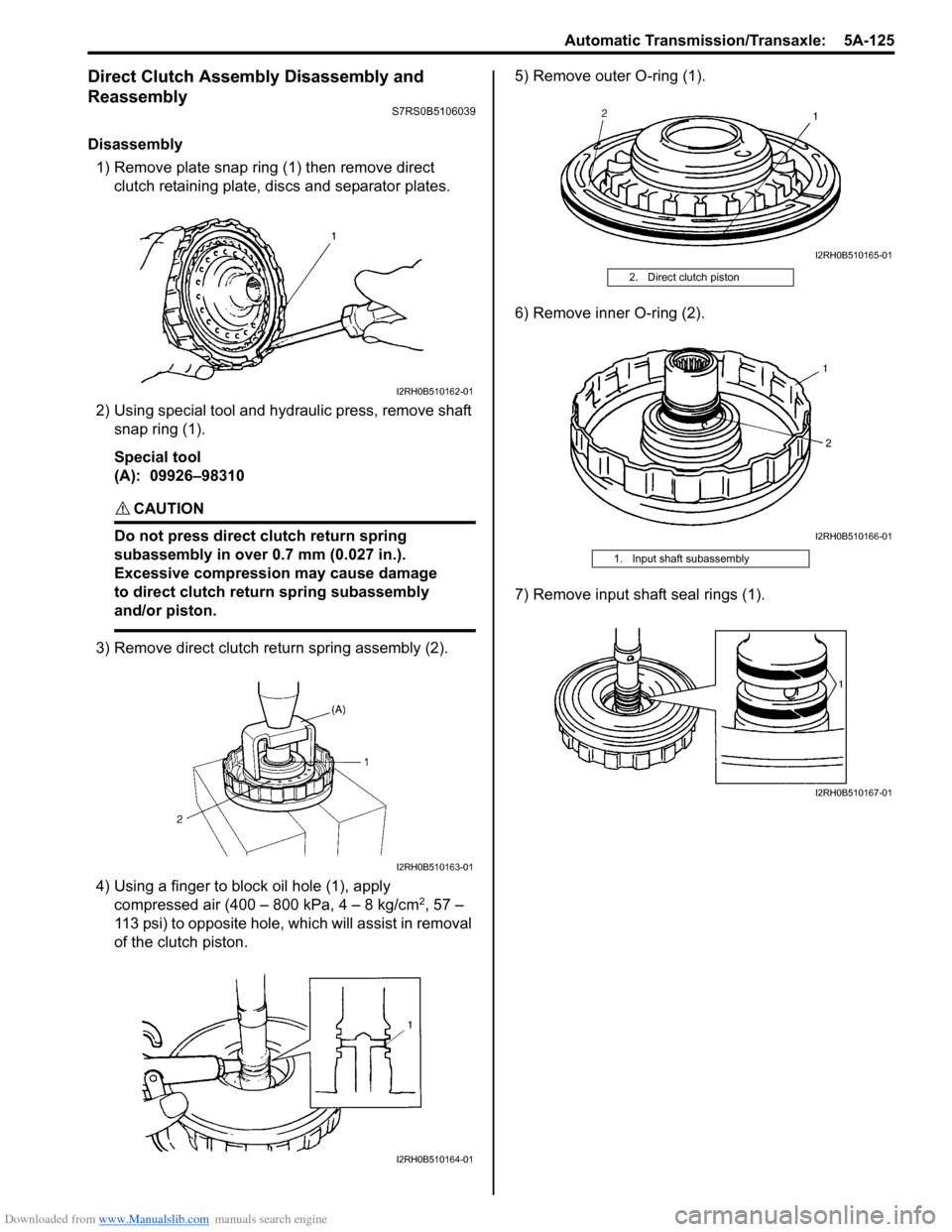
Disassembly1) Remove plate snap ring (1) then remove direct clutch retaining plate, discs and separator plates.
2) Using special tool and hydraulic press, remove shaft snap ring (1).
Special tool
(A): 09926–98310
CAUTION!
Do not press direct clutch return spring
subassembly in over 0.7 mm (0.027 in.).
Excessive compression may cause damage
to direct clutch return spring subassembly
and/or piston.
3) Remove direct clutch re turn spring assembly (2).
4) Using a finger to block oil hole (1), apply compressed air (400 – 800 kPa, 4 – 8 kg/cm
2, 57 –
113 psi) to opposite hole, which will assist in removal
of the clutch piston. 5) Remove outer O-ring (1).
6) Remove inner O-ring (2).
7) Remove input shaft seal rings (1).
I2RH0B510162-01
I2RH0B510163-01
I2RH0B510164-01
2. Direct clutch piston
1. Input shaft subassembly
I2RH0B510165-01
I2RH0B510166-01
I2RH0B510167-01
Page 823 of 1496
Downloaded from www.Manualslib.com manuals search engine Manual Transmission/Transaxle: 5B-9
Manual Transaxle Unit Dismounting and
Remounting
S7RS0B5206009
Dismounting1) Drain coolant and transaxle oil.
2) Remove coolant reservoir with reservoir hose.
3) Remove battery and tray.
4) Remove air cleaner case and resonator.
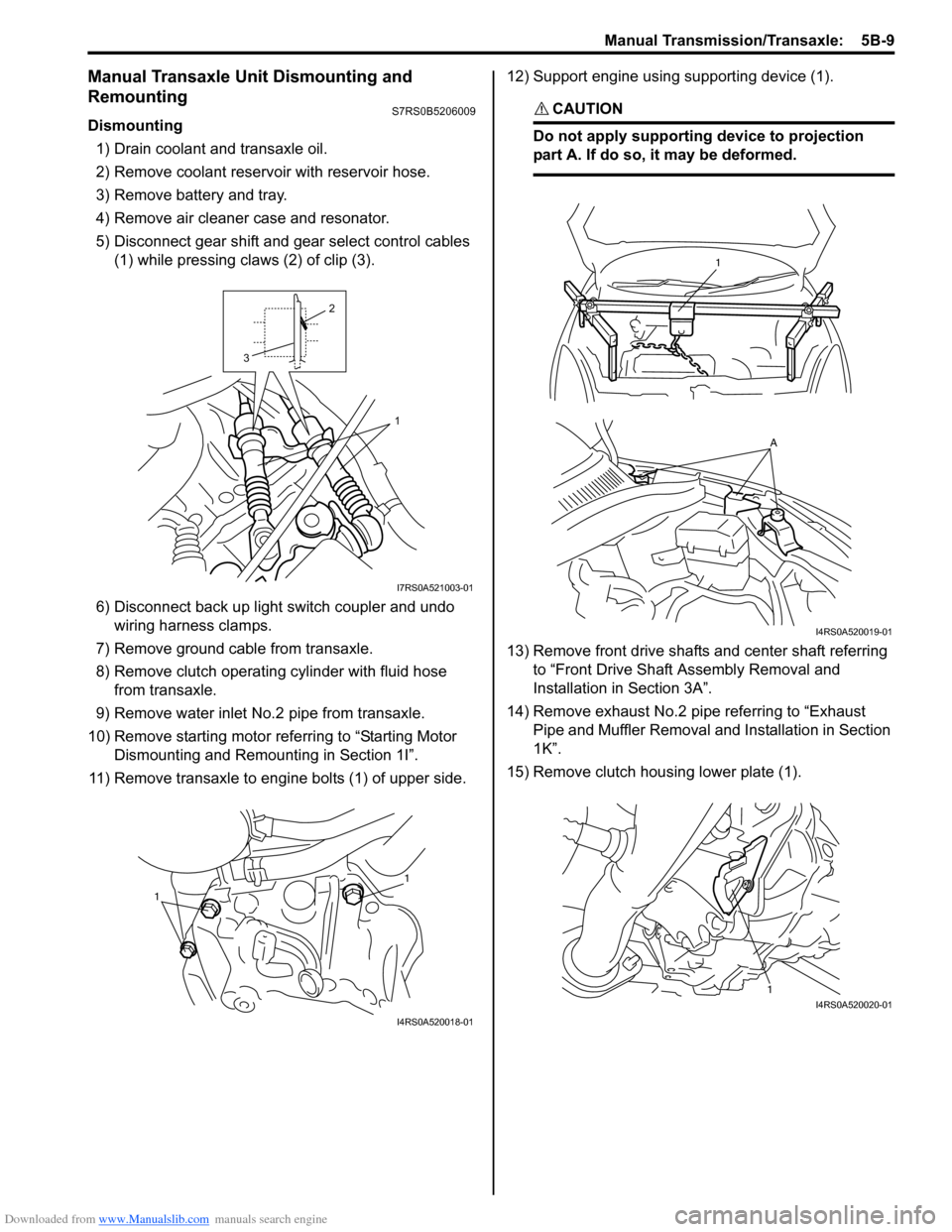
5) Disconnect gear shift and gear select control cables (1) while pressing claws (2) of clip (3).
6) Disconnect back up light switch coupler and undo wiring harness clamps.
7) Remove ground cable from transaxle.
8) Remove clutch operating cylinder with fluid hose from transaxle.
9) Remove water inlet No.2 pipe from transaxle.
10) Remove starting motor re ferring to “Starting Motor
Dismounting and Remounting in Section 1I”.
11) Remove transaxle to engine bolts (1) of upper side. 12) Support engine using supporting device (1).
CAUTION!
Do not apply supporting device to projection
part A. If do so, it may be deformed.
13) Remove front drive shafts and center shaft referring
to “Front Drive Shaft Assembly Removal and
Installation in Section 3A”.
14) Remove exhaust No.2 pipe referring to “Exhaust Pipe and Muffler Removal a nd Installation in Section
1K”.
15) Remove clutch housing lower plate (1).
1
2
3
I7RS0A521003-01
1
1
I4RS0A520018-01
1
A
I4RS0A520019-01
1I4RS0A520020-01
Page 856 of 1496
Downloaded from www.Manualslib.com manuals search engine 5C-4 Clutch:
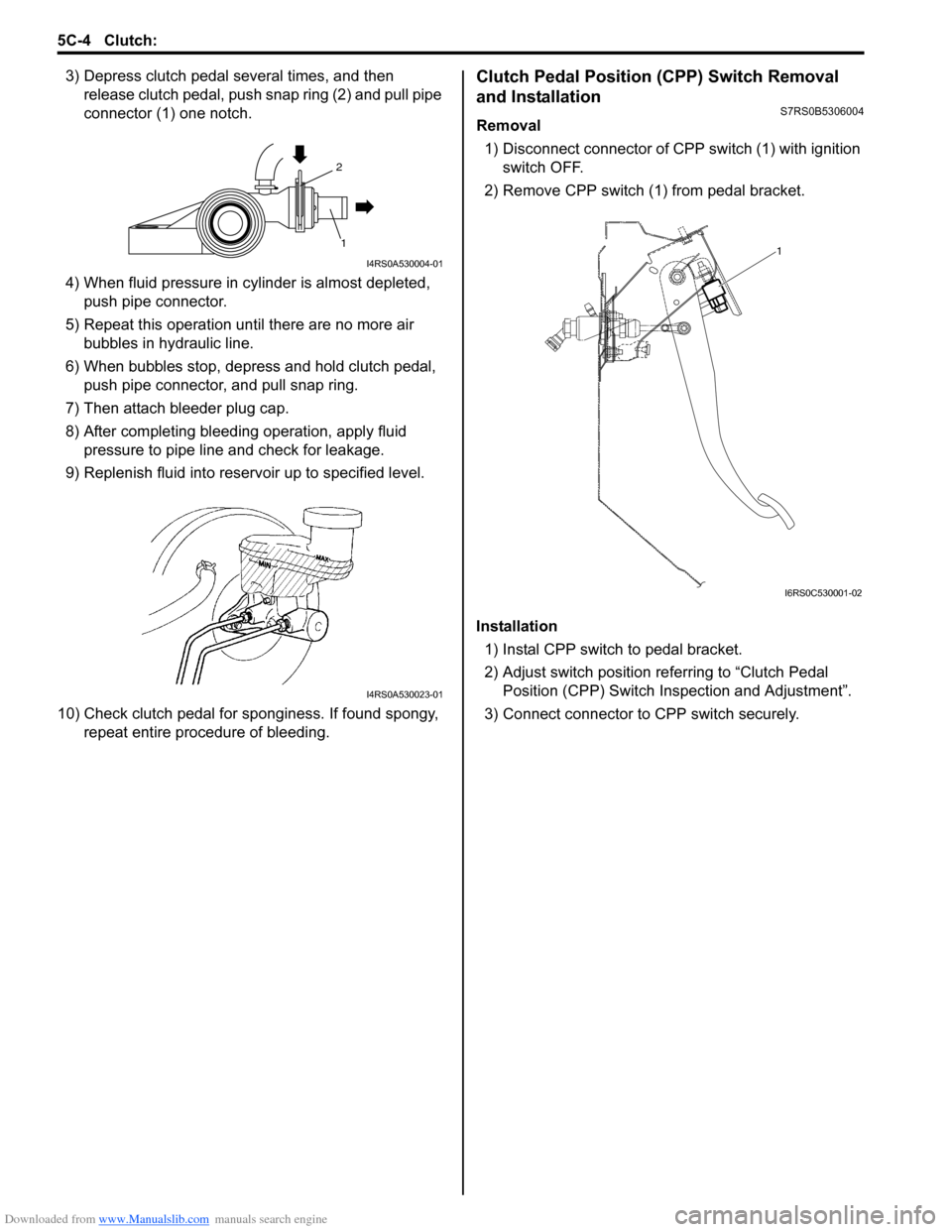
3) Depress clutch pedal several times, and then release clutch pedal, push snap ring (2) and pull pipe
connector (1) one notch.
4) When fluid pressure in cylinder is almost depleted, push pipe connector.
5) Repeat this operation until there are no more air bubbles in hydraulic line.
6) When bubbles stop, depress and hold clutch pedal, push pipe connector, and pull snap ring.
7) Then attach bleeder plug cap.
8) After completing bleeding operation, apply fluid pressure to pipe line and check for leakage.
9) Replenish fluid into reserv oir up to specified level.
10) Check clutch pedal for sponginess. If found spongy, repeat entire procedure of bleeding.Clutch Pedal Position (CPP) Switch Removal
and Installation
S7RS0B5306004
Removal
1) Disconnect connector of C PP switch (1) with ignition
switch OFF.
2) Remove CPP switch (1 ) from pedal bracket.
Installation 1) Instal CPP switch to pedal bracket.
2) Adjust switch position re ferring to “Clutch Pedal
Position (CPP) Switch Inspection and Adjustment”.
3) Connect connector to CPP switch securely.
2
1
I4RS0A530004-01
I4RS0A530023-01
1
I6RS0C530001-02
Page 858 of 1496
Downloaded from www.Manualslib.com manuals search engine 5C-6 Clutch:
Clutch Fluid Pipe Removal and InstallationS7RS0B5306007
Removal
CAUTION!
Do not allow fluid to get on painted surface. It
may cause painted surface damage.
1) Remove dust and dirt from each joint of pipe to be disconnected and clean around brake master
cylinder reservoir cap.
2) Take out fluid with syringe or such from brake master cylinder reservoir.
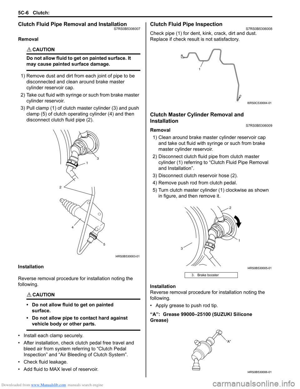
3) Pull clamp (1) of clutch master cylinder (3) and push clamp (5) of clutch operating cylinder (4) and then
disconnect clutch fluid pipe (2).
Installation
Reverse removal procedure for installation noting the
following.
CAUTION!
• Do not allow fluid to get on painted surface.
• Do not allow pipe to contact hard against vehicle body or other parts.
• Install each clamp securely.
• After installation, check clutch pedal free travel and bleed air from system referring to “Clutch Pedal
Inspection” and “Air Blee ding of Clutch System”.
• Check fluid leakage.
• Add fluid to MAX level of reservoir.
Clutch Fluid Pipe InspectionS7RS0B5306008
Check pipe (1) for dent, kink, crack, dirt and dust.
Replace if check result is not satisfactory.
Clutch Master Cylinder Removal and
Installation
S7RS0B5306009
Removal 1) Clean around brake master cylinder reservoir cap and take out fluid with syringe or such from brake
master cylinder reservoir.
2) Disconnect clutch fluid pipe from clutch master cylinder (1) referring to “C lutch Fluid Pipe Removal
and Installation”.
3) Disconnect clutch reservoir hose (2).
4) Remove push rod from clutch pedal.
5) Turn clutch master cylinder (1) clockwise as shown in figure, and then remove it.
Installation
Reverse removal procedure for installation noting the
following.
• Apply grease to push rod tip.
“A”: Grease 99000–25100 (SUZUKI Silicone
Grease)
31
2
5
4
I4RS0B530003-01
3. Brake booster
1
I6RS0C530004-01
1
2
3
I4RS0B530005-01
“A”
I4RS0B530006-01
Page 859 of 1496
Downloaded from www.Manualslib.com manuals search engine Clutch: 5C-7
Clutch Operating Cylinder Removal and
Installation
S7RS0B5306010
Removal1) Clean around brake master cylinder reservoir cap and take out fluid with syringe or such from brake
master cylinder reservoir.
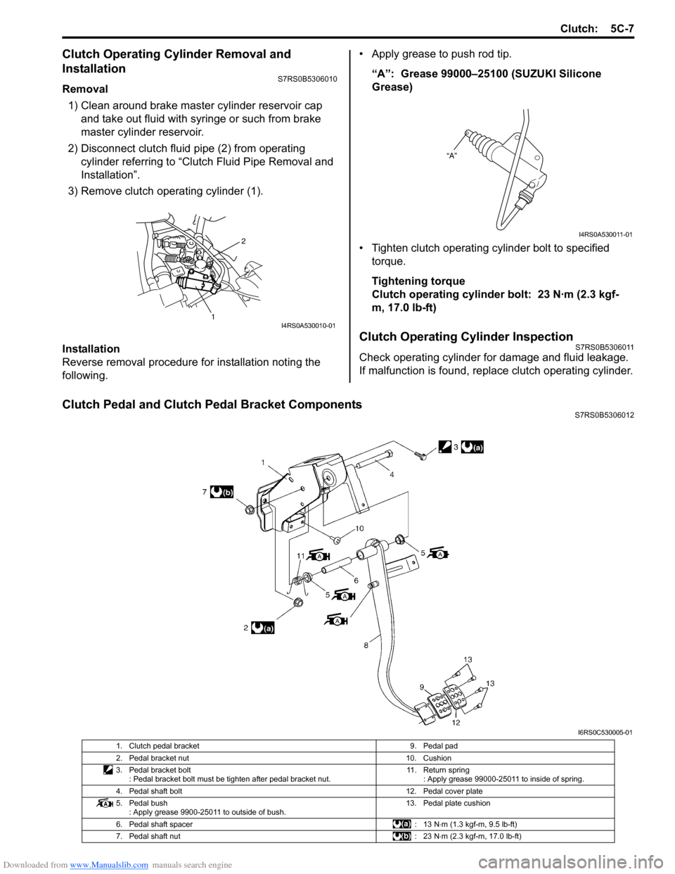
2) Disconnect clutch fluid pipe (2) from operating cylinder referring to “Clutch Fluid Pipe Removal and
Installation”.
3) Remove clutch operating cylinder (1).
Installation
Reverse removal procedure for installation noting the
following. • Apply grease to push rod tip.
“A”: Grease 99000–25100 (SUZUKI Silicone
Grease)
• Tighten clutch operating cylinder bolt to specified torque.
Tightening torque
Clutch operating cylinder bolt: 23 N·m (2.3 kgf-
m, 17.0 lb-ft)
Clutch Operating Cylinder InspectionS7RS0B5306011
Check operating cylinder for damage and fluid leakage.
If malfunction is found, repl ace clutch operating cylinder.
Clutch Pedal and Clutch Pedal Bracket ComponentsS7RS0B5306012
2
1I4RS0A530010-01
“A”
I4RS0A530011-01
I6RS0C530005-01
1. Clutch pedal bracket 9. Pedal pad
2. Pedal bracket nut 10. Cushion
3. Pedal bracket bolt : Pedal bracket bolt must be tighten after pedal bracket nut. 11. Return spring
: Apply grease 99000-25011 to inside of spring.
4. Pedal shaft bolt 12. Pedal cover plate
5. Pedal bush : Apply grease 9900-25011 to outside of bush. 13. Pedal plate cushion
6. Pedal shaft spacer : 13 N⋅m (1.3 kgf-m, 9.5 lb-ft)
7. Pedal shaft nut : 23 N⋅m (2.3 kgf-m, 17.0 lb-ft)
Page 860 of 1496
Downloaded from www.Manualslib.com manuals search engine 5C-8 Clutch:
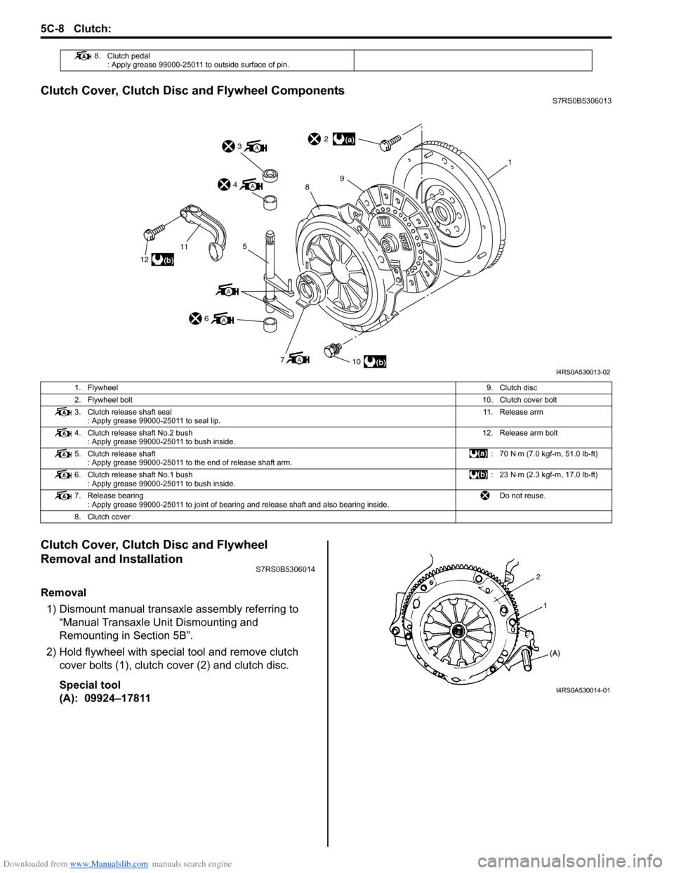
Clutch Cover, Clutch Disc and Flywheel ComponentsS7RS0B5306013
Clutch Cover, Clutch Disc and Flywheel
Removal and Installation
S7RS0B5306014
Removal1) Dismount manual transaxle assembly referring to “Manual Transaxle Unit Dismounting and
Remounting in Section 5B”.
2) Hold flywheel with specia l tool and remove clutch
cover bolts (1), clutch cover (2) and clutch disc.
Special tool
(A): 09924–17811
8. Clutch pedal : Apply grease 99000-25011 to outside surface of pin.
(a)
(b)
(b)
A
A
A
12
115
6
A3
A4
710
2
98
1
I4RS0A530013-02
1. Flywheel 9. Clutch disc
2. Flywheel bolt 10. Clutch cover bolt
3. Clutch release shaft seal : Apply grease 99000-25011 to seal lip. 11. Release arm
4. Clutch release shaft No.2 bush : Apply grease 99000-25011 to bush inside. 12. Release arm bolt
5. Clutch release shaft : Apply grease 99000-25011 to the end of release shaft arm. :70 N
⋅m (7.0 kgf-m, 51.0 lb-ft)
6. Clutch release shaft No.1 bush : Apply grease 99000-25011 to bush inside. :23 N
⋅m (2.3 kgf-m, 17.0 lb-ft)
7. Release bearing : Apply grease 99000-25011 to joint of bearing and release shaft and also bearing inside. Do not reuse.
8. Clutch cover
I4RS0A530014-01
Page 863 of 1496
Downloaded from www.Manualslib.com manuals search engine Clutch: 5C-11
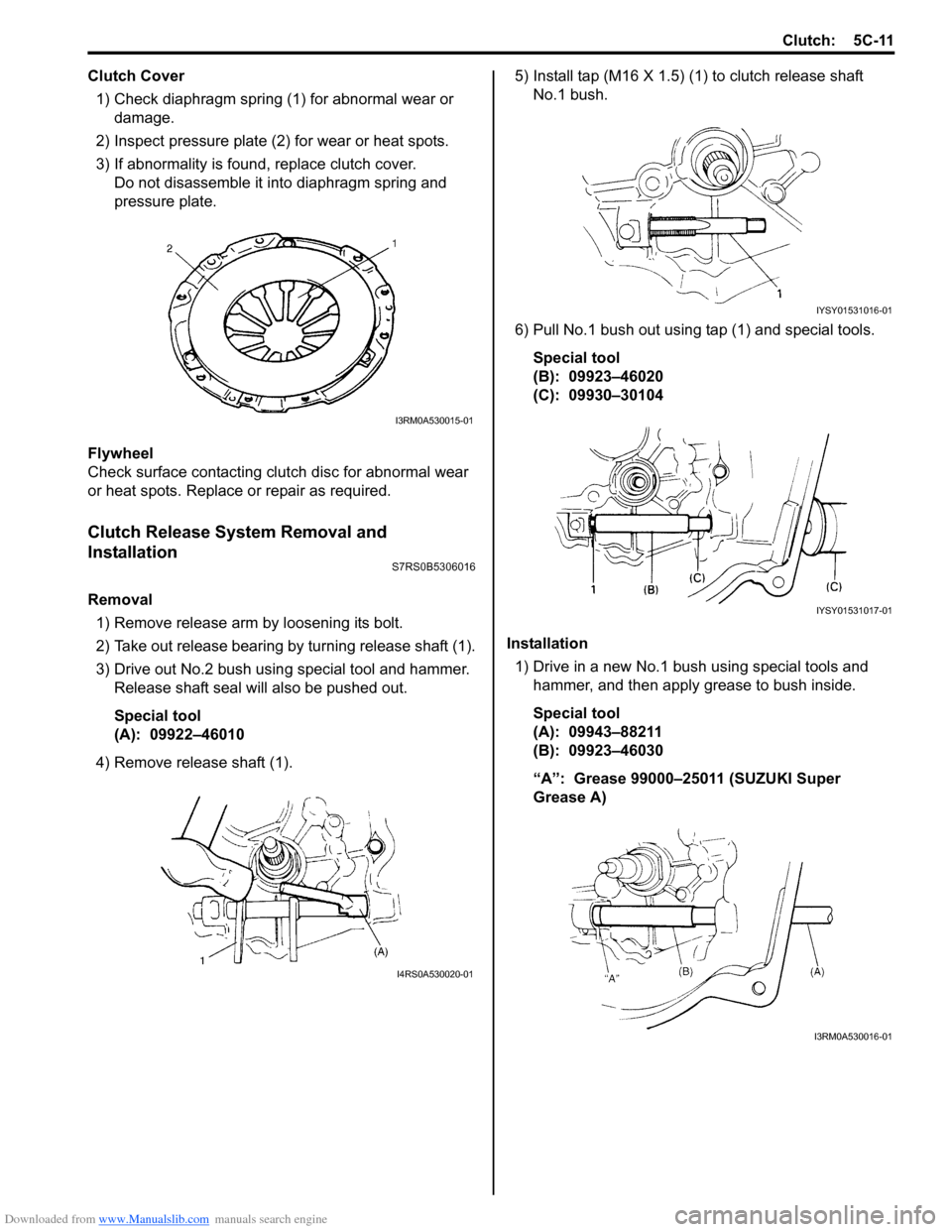
Clutch Cover1) Check diaphragm spring (1) for abnormal wear or damage.
2) Inspect pressure plate (2) for wear or heat spots.
3) If abnormality is found, replace clutch cover. Do not disassemble it into diaphragm spring and
pressure plate.
Flywheel
Check surface contacting clutch disc for abnormal wear
or heat spots. Replace or repair as required.
Clutch Release System Removal and
Installation
S7RS0B5306016
Removal 1) Remove release arm by loosening its bolt.
2) Take out release bearing by turning release shaft (1).
3) Drive out No.2 bush usin g special tool and hammer.
Release shaft seal will also be pushed out.
Special tool
(A): 09922–46010
4) Remove release shaft (1). 5) Install tap (M16 X 1.5) (1) to clutch release shaft
No.1 bush.
6) Pull No.1 bush out using tap (1) and special tools. Special tool
(B): 09923–46020
(C): 09930–30104
Installation 1) Drive in a new No.1 bush using special tools and
hammer, and then apply grease to bush inside.
Special tool
(A): 09943–88211
(B): 09923–46030
“A”: Grease 99000–25011 (SUZUKI Super
Grease A)
I3RM0A530015-01
I4RS0A530020-01
IYSY01531016-01
IYSY01531017-01
I3RM0A530016-01