Engine fail SUZUKI SWIFT 2006 2.G Service User Guide
[x] Cancel search | Manufacturer: SUZUKI, Model Year: 2006, Model line: SWIFT, Model: SUZUKI SWIFT 2006 2.GPages: 1496, PDF Size: 34.44 MB
Page 83 of 1496
Downloaded from www.Manualslib.com manuals search engine Engine General Information and Diagnosis: 1A-33
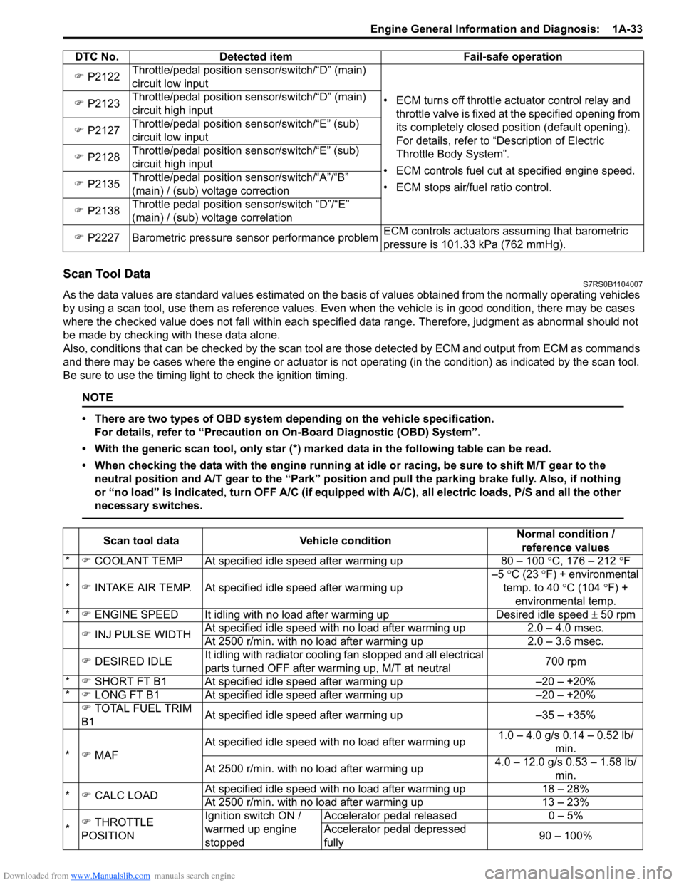
Scan Tool DataS7RS0B1104007
As the data values are standard values estimated on the basis of values obtained from the normally operating vehicles
by using a scan tool, use them as re ference values. Even when the vehicle is in good condition, there may be cases
where the checked value does not fall within each specified data range. Therefore, judgment as abnormal should not
be made by checking with these data alone.
Also, conditions that can be checked by the scan tool are those detected by ECM and output from ECM as commands
and there may be cases where the engine or actuator is not operating (in the condition) as indicated by the scan tool.
Be sure to use the timing light to check the ignition timing.
NOTE
• There are two types of OBD system depending on the vehicle specification.
For details, refer to “Precaution on On-Board Diagnostic (OBD) System”.
• With the generic scan tool, only star (*) marked data in the following table can be read.
• When checking the data with the engine running at idle or racing, be sure to shift M/T gear to the neutral position and A/T gear to the “Park” position and pull the parking brake fully. Also, if nothing
or “no load” is indicated, turn O FF A/C (if equipped with A/C), all electric loads, P/S and all the other
necessary switches.
�) P2122 Throttle/pedal position sensor/switch/“D” (main)
circuit low input
• ECM turns off throttle actuator control relay and throttle valve is fixed at the specified opening from
its completely closed position (default opening).
For details, refer to “Description of Electric
Throttle Body System”.
• ECM controls fuel cut at specified engine speed.
• ECM stops air/fuel ratio control.
�)
P2123 Throttle/pedal position sensor/switch/“D” (main)
circuit high input
�) P2127 Throttle/pedal position sensor/switch/“E” (sub)
circuit low input
�) P2128 Throttle/pedal position sensor/switch/“E” (sub)
circuit high input
�) P2135 Throttle/pedal position sensor/switch/“A”/“B”
(main) / (sub) voltage correction
�) P2138 Throttle pedal position sensor/switch “D”/“E”
(main) / (sub) voltage correlation
�) P2227 Barometric pressure sensor performance problem ECM controls actuators assuming that barometric
pressure is 101.33 kPa (762 mmHg).
DTC No. Detected item Fail-safe operation
Scan tool data
Vehicle condition Normal condition /
reference values
* �) COOLANT TEMP At specified idle speed after warming up 80 – 100 °C, 176 – 212 °F
* �) INTAKE AIR TEMP. At specifie d idle speed after warming up –5
°C (23 °F) + environmental
temp. to 40 °C (104 °F) +
environmental temp.
* �) ENGINE SPEED It idling with no load after warming upDesired idle speed ± 50 rpm
�) INJ PULSE WIDTH At specified idle speed with no load after warming up
2.0 – 4.0 msec.
At 2500 r/min. with no load after warming up 2.0 – 3.6 msec.
�) DESIRED IDLE It idling with radiator cooling fan stopped and all electrical
parts turned OFF after warming up, M/T at neutral 700 rpm
* �) SHORT FT B1 At specified idle speed after warming up –20 – +20%
* �) LONG FT B1 At specified idle speed after warming up –20 – +20%
�) TOTAL FUEL TRIM
B1 At specified idle speed after warming up
–35 – +35%
* �) MAF At specified idle speed wit
h no load after warming up 1.0 – 4.0 g/s 0.14 – 0.52 lb/
min.
At 2500 r/min. with no load after warming up 4.0 – 12.0 g/s 0.53 – 1.58 lb/
min.
* �) CALC LOAD At specified idle speed with no load after warming up
18 – 28%
At 2500 r/min. with no load after warming up 13 – 23%
* �)
THROTTLE
POSITION Ignition switch ON /
warmed up engine
stoppedAccelerator pedal released
0 – 5%
Accelerator pedal depressed
fully 90 – 100%
Page 93 of 1496
Downloaded from www.Manualslib.com manuals search engine Engine General Information and Diagnosis: 1A-43
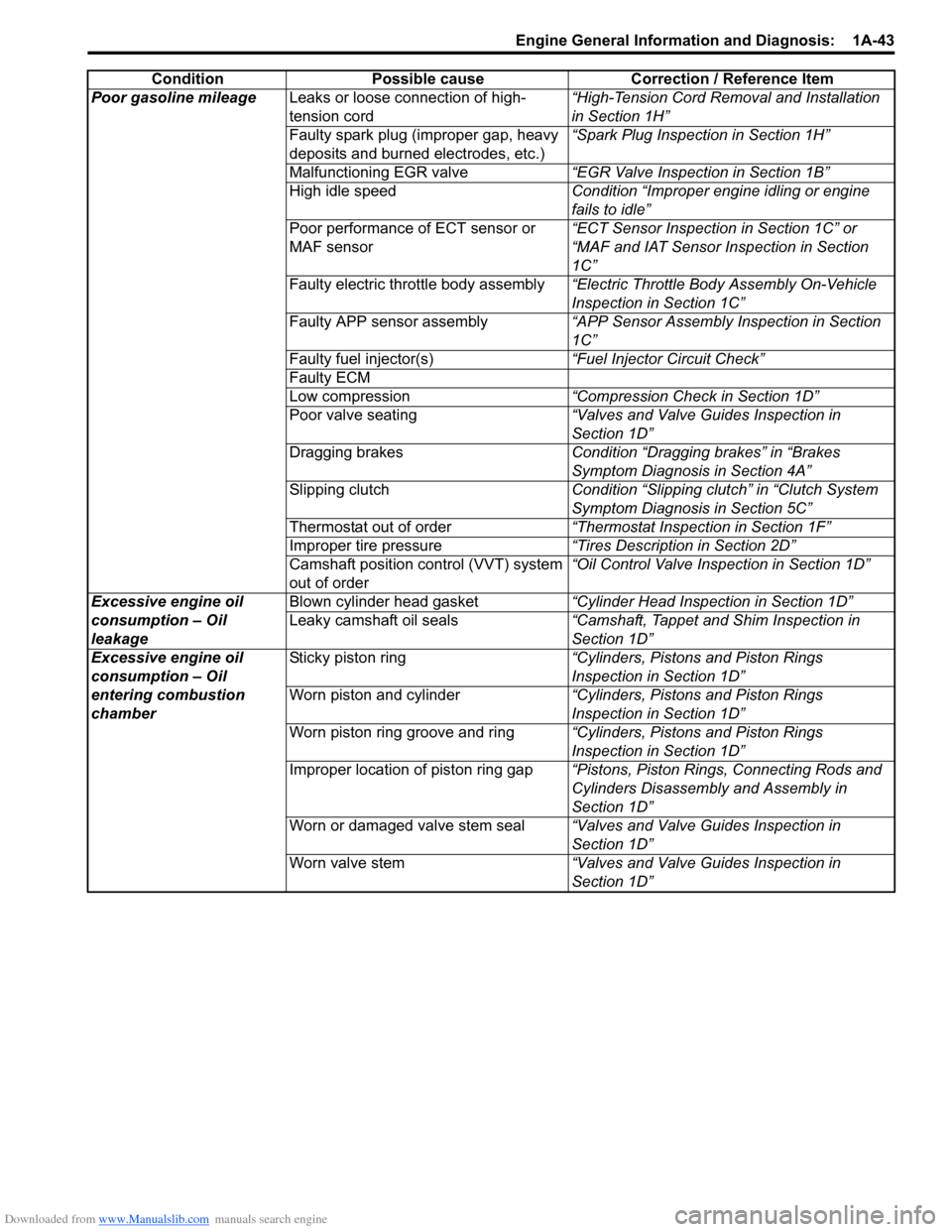
Poor gasoline mileageLeaks or loose connection of high-
tension cord “High-Tension Cord Removal and Installation
in Section 1H”
Faulty spark plug (improper gap, heavy
deposits and burned electrodes, etc.) “Spark Plug Inspection in Section 1H”
Malfunctioning EGR valve “EGR Valve Inspection in Section 1B”
High idle speed Condition “Improper engine idling or engine
fails to idle”
Poor performance of ECT sensor or
MAF sensor “ECT Sensor Inspection in Section 1C” or
“MAF and IAT Sensor Inspection in Section
1C”
Faulty electric throttle body assembly “Electric Throttle Body Assembly On-Vehicle
Inspection in Section 1C”
Faulty APP sensor assembly “APP Sensor Assembly Inspection in Section
1C”
Faulty fuel injector(s) “Fuel Injector Circuit Check”
Faulty ECM
Low compression “Compression Check in Section 1D”
Poor valve seating “Valves and Valve Guides Inspection in
Section 1D”
Dragging brakes Condition “Dragging brakes” in “Brakes
Symptom Diagnosis in Section 4A”
Slipping clutch Condition “Slipping clutch” in “Clutch System
Symptom Diagnosis in Section 5C”
Thermostat out of order “Thermostat Inspection in Section 1F”
Improper tire pressure “Tires Description in Section 2D”
Camshaft position control (VVT) system
out of order “Oil Control Valve Inspection in Section 1D”
Excessive engine oil
consumption – Oil
leakage Blown cylinder head gasket
“Cylinder Head Inspection in Section 1D”
Leaky camshaft oil seals “Camshaft, Tappet and Shim Inspection in
Section 1D”
Excessive engine oil
consumption – Oil
entering combustion
chamber Sticky piston ring
“Cylinders, Pistons and Piston Rings
Inspection in Section 1D”
Worn piston and cylinder “Cylinders, Pistons and Piston Rings
Inspection in Section 1D”
Worn piston ring groove and ring “Cylinders, Pistons and Piston Rings
Inspection in Section 1D”
Improper location of piston ring gap “Pistons, Piston Rings, Connecting Rods and
Cylinders Disassembly and Assembly in
Section 1D”
Worn or damaged valve stem seal “Valves and Valve Guides Inspection in
Section 1D”
Worn valve stem “Valves and Valve Guides Inspection in
Section 1D”
Condition Possible cause Correction / Reference Item
Page 95 of 1496
Downloaded from www.Manualslib.com manuals search engine Engine General Information and Diagnosis: 1A-45
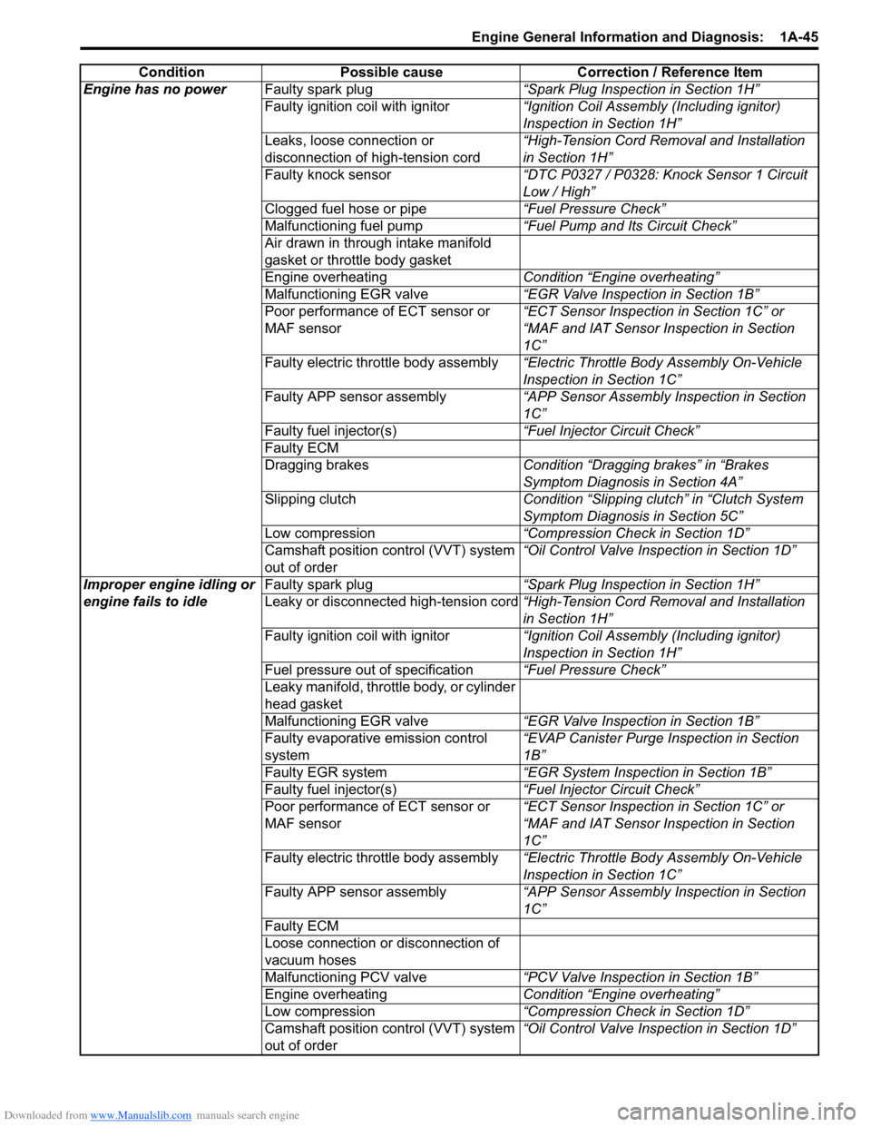
Engine has no powerFaulty spark plug “Spark Plug Inspection in Section 1H”
Faulty ignition coil with ignitor “Ignition Coil Assembly (Including ignitor)
Inspection in Section 1H”
Leaks, loose connection or
disconnection of high-tension cord “High-Tension Cord Removal and Installation
in Section 1H”
Faulty knock sensor “DTC P0327 / P0328: Knock Sensor 1 Circuit
Low / High”
Clogged fuel hose or pipe “Fuel Pressure Check”
Malfunctioning fuel pump “Fuel Pump and Its Circuit Check”
Air drawn in through intake manifold
gasket or throttle body gasket
Engine overheating Condition “Engine overheating”
Malfunctioning EGR valve “EGR Valve Inspection in Section 1B”
Poor performance of ECT sensor or
MAF sensor “ECT Sensor Inspection in Section 1C” or
“MAF and IAT Sensor Inspection in Section
1C”
Faulty electric throttle body assembly “Electric Throttle Body Assembly On-Vehicle
Inspection in Section 1C”
Faulty APP sensor assembly “APP Sensor Assembly Inspection in Section
1C”
Faulty fuel injector(s) “Fuel Injector Circuit Check”
Faulty ECM
Dragging brakes Condition “Dragging brakes” in “Brakes
Symptom Diagnosis in Section 4A”
Slipping clutch Condition “Slipping clutch” in “Clutch System
Symptom Diagnosis in Section 5C”
Low compression “Compression Check in Section 1D”
Camshaft position control (VVT) system
out of order “Oil Control Valve Inspection in Section 1D”
Improper engine idling or
engine fails to idle Faulty spark plug
“Spark Plug Inspection in Section 1H”
Leaky or disconnected high-tension cord “High-Tension Cord Removal and Installation
in Section 1H”
Faulty ignition coil with ignitor “Ignition Coil Assembly (Including ignitor)
Inspection in Section 1H”
Fuel pressure out of specification “Fuel Pressure Check”
Leaky manifold, throttle body, or cylinder
head gasket
Malfunctioning EGR valve “EGR Valve Inspection in Section 1B”
Faulty evaporative emission control
system “EVAP Canister Purge Inspection in Section
1B”
Faulty EGR system “EGR System Inspection in Section 1B”
Faulty fuel injector(s) “Fuel Injector Circuit Check”
Poor performance of ECT sensor or
MAF sensor “ECT Sensor Inspection in Section 1C” or
“MAF and IAT Sensor Inspection in Section
1C”
Faulty electric throttle body assembly “Electric Throttle Body Assembly On-Vehicle
Inspection in Section 1C”
Faulty APP sensor assembly “APP Sensor Assembly Inspection in Section
1C”
Faulty ECM
Loose connection or disconnection of
vacuum hoses
Malfunctioning PCV valve “PCV Valve Inspection in Section 1B”
Engine overheating Condition “Engine overheating”
Low compression “Compression Check in Section 1D”
Camshaft position control (VVT) system
out of order “Oil Control Valve Inspection in Section 1D”
Condition Possible cause Correction / Reference Item
Page 96 of 1496
Downloaded from www.Manualslib.com manuals search engine 1A-46 Engine General Information and Diagnosis:
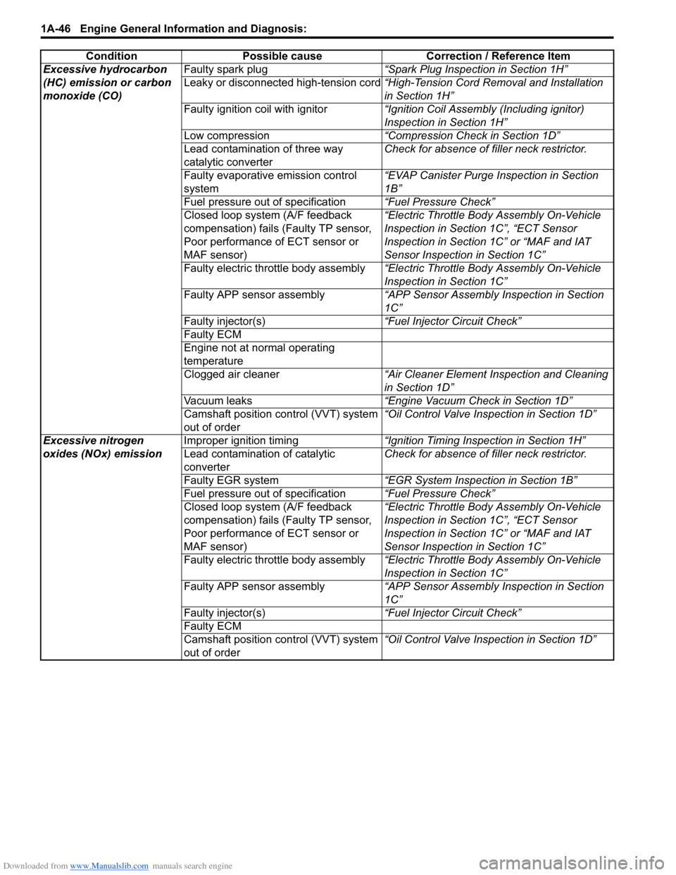
Excessive hydrocarbon
(HC) emission or carbon
monoxide (CO)Faulty spark plug
“Spark Plug Inspection in Section 1H”
Leaky or disconnected high-tension cord “High-Tension Cord Removal and Installation
in Section 1H”
Faulty ignition coil with ignitor “Ignition Coil Assembly (Including ignitor)
Inspection in Section 1H”
Low compression “Compression Check in Section 1D”
Lead contamination of three way
catalytic converter Check for absence of f
iller neck restrictor.
Faulty evaporative emission control
system “EVAP Canister Purge Inspection in Section
1B”
Fuel pressure out of specification “Fuel Pressure Check”
Closed loop system (A/F feedback
compensation) fails (Faulty TP sensor,
Poor performance of ECT sensor or
MAF sensor) “Electric Throttle Body Assembly On-Vehicle
Inspection in Section 1C”, “ECT Sensor
Inspection in Section 1C” or “MAF and IAT
Sensor Inspection in Section 1C”
Faulty electric throttle body assembly “Electric Throttle Body Assembly On-Vehicle
Inspection in Section 1C”
Faulty APP sensor assembly “APP Sensor Assembly Inspection in Section
1C”
Faulty injector(s) “Fuel Injector Circuit Check”
Faulty ECM
Engine not at normal operating
temperature
Clogged air cleaner “Air Cleaner Element Inspection and Cleaning
in Section 1D”
Vacuum leaks “Engine Vacuum Check in Section 1D”
Camshaft position control (VVT) system
out of order “Oil Control Valve Inspection in Section 1D”
Excessive nitrogen
oxides (NOx) emission Improper ignition timing
“Ignition Timing Inspection in Section 1H”
Lead contamination of catalytic
converter Check for absence of f
iller neck restrictor.
Faulty EGR system “EGR System Inspection in Section 1B”
Fuel pressure out of specification “Fuel Pressure Check”
Closed loop system (A/F feedback
compensation) fails (Faulty TP sensor,
Poor performance of ECT sensor or
MAF sensor) “Electric Throttle Body Assembly On-Vehicle
Inspection in Section 1C”, “ECT Sensor
Inspection in Section 1C” or “MAF and IAT
Sensor Inspection in Section 1C”
Faulty electric throttle body assembly “Electric Throttle Body Assembly On-Vehicle
Inspection in Section 1C”
Faulty APP sensor assembly “APP Sensor Assembly Inspection in Section
1C”
Faulty injector(s) “Fuel Injector Circuit Check”
Faulty ECM
Camshaft position control (VVT) system
out of order “Oil Control Valve Inspection in Section 1D”
Condition Possible cause Correction / Reference Item
Page 100 of 1496
Downloaded from www.Manualslib.com manuals search engine 1A-50 Engine General Information and Diagnosis:
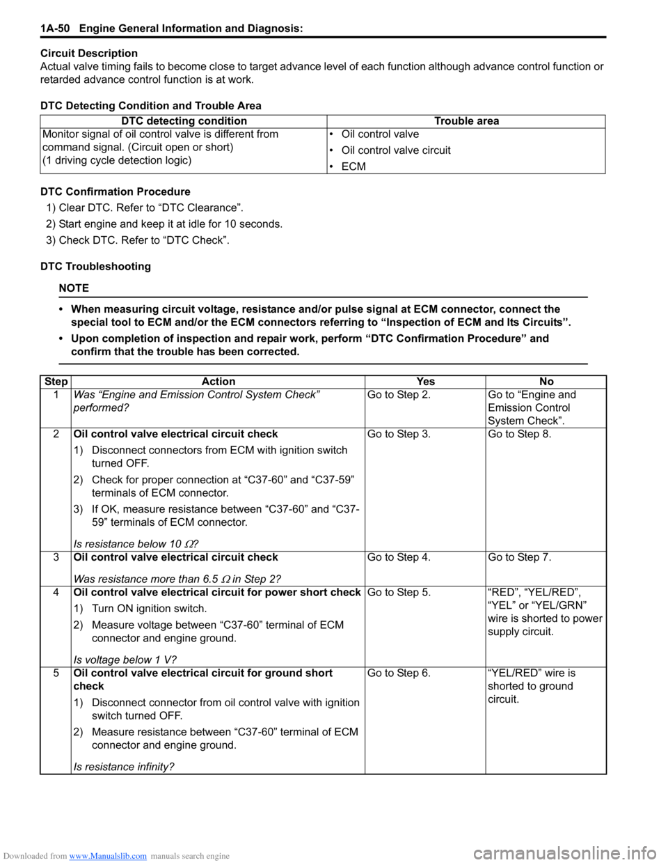
Circuit Description
Actual valve timing fails to become close to target advance level of each function although advance control function or
retarded advance control function is at work.
DTC Detecting Condition and Trouble Area
DTC Confirmation Procedure 1) Clear DTC. Refer to “DTC Clearance”.
2) Start engine and keep it at idle for 10 seconds.
3) Check DTC. Refer to “DTC Check”.
DTC Troubleshooting
NOTE
• When measuring circuit voltage, resistance and/ or pulse signal at ECM connector, connect the
special tool to ECM and/or the ECM connectors re ferring to “Inspection of ECM and Its Circuits”.
• Upon completion of inspection and repair work, perform “DTC Confirmation Procedure” and confirm that the trouble has been corrected.
DTC detecting condition Trouble area
Monitor signal of oil control valve is different from
command signal. (Circuit open or short)
(1 driving cycle detection logic) • Oil control valve
• Oil control valve circuit
•ECM
Step
Action YesNo
1 Was “Engine and Emission Control System Check”
performed? Go to Step 2.
Go to “Engine and
Emission Control
System Check”.
2 Oil control valve electrical circuit check
1) Disconnect connectors from ECM with ignition switch
turned OFF.
2) Check for proper connection at “C37-60” and “C37-59” terminals of ECM connector.
3) If OK, measure resistance between “C37-60” and “C37- 59” terminals of ECM connector.
Is resistance below 10
Ω? Go to Step 3. Go to Step 8.
3 Oil control valve electrical circuit check
Was resistance more than 6.5
Ω in Step 2? Go to Step 4. Go to Step 7.
4 Oil control valve electrical circuit for power short check
1) Turn ON ignition switch.
2) Measure voltage between “C37-60” terminal of ECM
connector and engine ground.
Is voltage below 1 V? Go to Step 5. “RED”, “YEL/RED”,
“YEL” or “YEL/GRN”
wire is shorted to power
supply circuit.
5 Oil control valve electrical circuit for ground short
check
1) Disconnect connector from oil control valve with ignition
switch turned OFF.
2) Measure resistance between “C37-60” terminal of ECM connector and engine ground.
Is resistance infinity? Go to Step 6. “YEL/RED” wire is
shorted to ground
circuit.
Page 314 of 1496
Downloaded from www.Manualslib.com manuals search engine 1D-29 Engine Mechanical:
Camshaft, Tappet and Shim Removal and
Installation
S7RS0B1406021
CAUTION!
• Keep working table, tools and hands clean while overhauling.
• Use special care to handle aluminum parts so as not to damage them.
• Do not expose removed parts to dust. Keep them always clean.
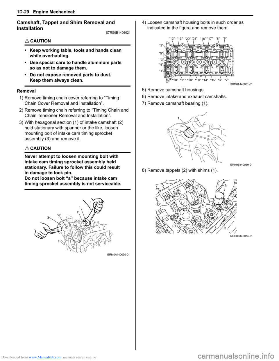
Removal
1) Remove timing chain cover referring to “Timing Chain Cover Removal and Installation”.
2) Remove timing chain referring to “Timing Chain and Chain Tensioner Removal and Installation”.
3) With hexagonal section (1) of intake camshaft (2) held stationary with spanner or the like, loosen
mounting bolt of intake cam timing sprocket
assembly (3) and remove it.
CAUTION!
Never attempt to loosen mounting bolt with
intake cam timing sprocket assembly held
stationary. Failure to fo llow this could result
in damage to lock pin.
Do not loosen bolt “a” because intake cam
timing sprocket assembly is not serviceable.
4) Loosen camshaft housing bolts in such order as indicated in the figure and remove them.
5) Remove camshaft housings.
6) Remove intake and exhaust camshafts.
7) Remove camshaft bearing (1).
8) Remove tappets (2) with shims (1).
3“a”
1
2
I3RM0A140030-01
“12”“13” “20”“21”
“16”“17” “8” “9”
“2”
“5” “3”
“4”
“1”
“10”“11”“18”
“19” “14” “15” “6” “7”
I3RM0A140031-01
1
I3RH0B140039-01
I2RH0B140074-01
Page 327 of 1496
Downloaded from www.Manualslib.com manuals search engine Engine Mechanical: 1D-42
Cylinder Head InspectionS7RS0B1406027
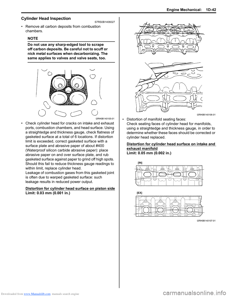
• Remove all carbon deposits from combustion chambers.
NOTE
Do not use any sharp-edged tool to scrape
off carbon deposits. Be careful not to scuff or
nick metal surfaces when decarbonizing. The
same applies to valves and valve seats, too.
• Check cylinder head for cracks on intake and exhaust ports, combustion chambers, and head surface. Using
a straightedge and thickness gauge, check flatness of
gasketed surface at a total of 6 locations. If distortion
limit is exceeded, correct gasketed surface with a
surface plate and abrasive paper of about #400
(Waterproof silicon carbide abrasive paper): place
abrasive paper on and over surface plate, and rub
gasketed surface against paper to grind off high spots.
Should this fail to reduce thickness gauge readings to
within limit, replace cylinder head.
Leakage of combustion gases from this gasketed joint
is often due to warped gasketed surface: such
leakage results in reduced power output.
Distortion for cylinder head surface on piston side
Limit: 0.03 mm (0.001 in.) • Distortion of manifold seating faces:
Check seating faces of cylinder head for manifolds,
using a straightedge and thickness gauge, in order to
determine whether these faces should be corrected or
cylinder head replaced.
Distortion for cylinder head surface on intake and
exhaust manifold
Limit: 0.05 mm (0.002 in.)
I2RH0B140105-01
I2RH0B140106-01
I2RH0B140107-01
Page 385 of 1496
Downloaded from www.Manualslib.com manuals search engine Fuel System: 1G-10
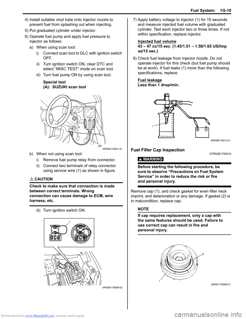
4) Install suitable vinyl tube onto injector nozzle to
prevent fuel from splashing out when injecting.
5) Put graduated cylinder under injector.
6) Operate fuel pump and apply fuel pressure to
injector as follows:
a) When using scan tool:
i) Connect scan tool to DLC with ignition switch OFF.
ii) Turn ignition switch ON, clear DTC and select “MISC TEST” mode on scan tool.
iii) Turn fuel pump ON by using scan tool.
Special tool
(A): SUZUKI scan tool
b) When not using scan tool: i) Remove fuel pump relay from connector.
ii) Connect two terminals of relay connector using service wire (1) as shown in figure.
CAUTION!
Check to make sure that connection is made
between correct terminals. Wrong
connection can cause damage to ECM, wire
harness, etc.
iii) Turn ignition switch ON. 7) Apply battery voltage to in
jector (1) for 15 seconds
and measure injected fuel volume with graduated
cylinder. Test each injector two or three times. If not
within specification, replace injector.
Injected fuel volume
43 – 47 cc/15 sec. (1.45/1.51 – 1.58/1.65 US/lmp
oz/15 sec.)
8) Check fuel leakage from injector nozzle. Do not operate injector for this check (but fuel pump should
be at work). If fuel leaks (1) more than the following
specifications, replace.
Fuel leakage
Less than 1 drop/min.
Fuel Filler Cap InspectionS7RS0B1706010
WARNING!
Before starting the following procedure, be
sure to observe “Precautions on Fuel System
Service” in order to reduce the risk or fire
and personal injury.
Remove cap (1), and che ck gasket for even filler neck
imprint, and deterioration or any damage. If gasket (2) is
in malcondition, replace cap.
NOTE
If cap requires replacement, only a cap with
the same features should be used. Failure to
use correct cap can result in fire and
personal injury.
(A)I4RS0A170021-01
1
I4RS0A170006-02
I2RH0B170013-01
I2RH01170008-01
Page 390 of 1496
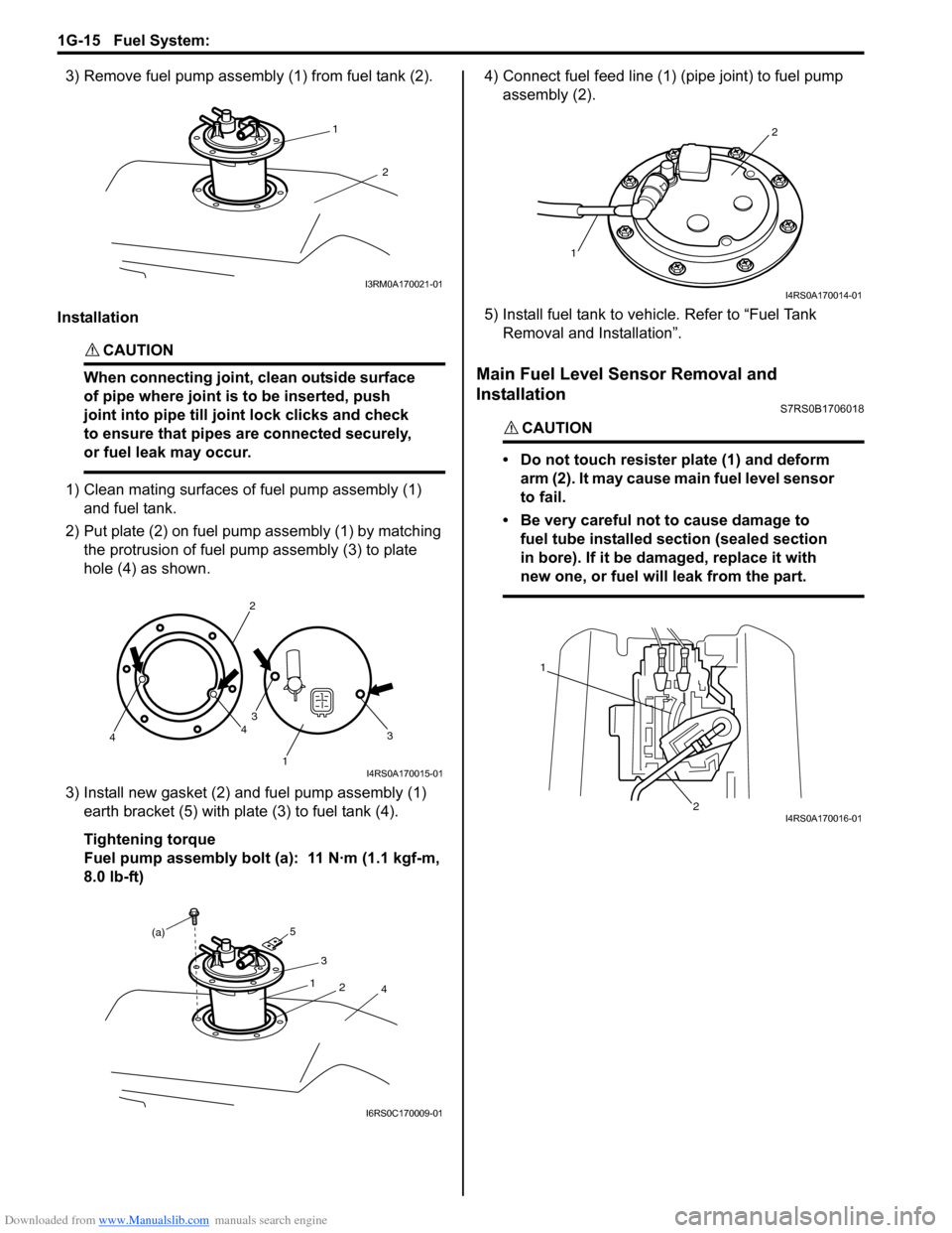
Downloaded from www.Manualslib.com manuals search engine 1G-15 Fuel System:
3) Remove fuel pump assembly (1) from fuel tank (2).
Installation
CAUTION!
When connecting joint, clean outside surface
of pipe where joint is to be inserted, push
joint into pipe till jo int lock clicks and check
to ensure that pipes are connected securely,
or fuel leak may occur.
1) Clean mating surfaces of fuel pump assembly (1) and fuel tank.
2) Put plate (2) on fuel pump assembly (1) by matching the protrusion of fuel pump assembly (3) to plate
hole (4) as shown.
3) Install new gasket (2) and fuel pump assembly (1) earth bracket (5) with plate (3) to fuel tank (4).
Tightening torque
Fuel pump assembly bolt (a): 11 N·m (1.1 kgf-m,
8.0 lb-ft) 4) Connect fuel feed line (1) (pipe joint) to fuel pump
assembly (2).
5) Install fuel tank to vehi cle. Refer to “Fuel Tank
Removal and Installation”.
Main Fuel Level Sensor Removal and
Installation
S7RS0B1706018
CAUTION!
• Do not touch resister plate (1) and deform arm (2). It may cause main fuel level sensor
to fail.
• Be very careful not to cause damage to fuel tube installed section (sealed section
in bore). If it be damaged, replace it with
new one, or fuel will leak from the part.
1
2
I3RM0A170021-01
3
1
3
2
44
I4RS0A170015-01
3
1 2
(a)
4
5
I6RS0C170009-01
2
1
I4RS0A170014-01
1
2I4RS0A170016-01
Page 402 of 1496
Downloaded from www.Manualslib.com manuals search engine 1I-1 Starting System:
Engine
Starting System
Schematic and Routing Diagram
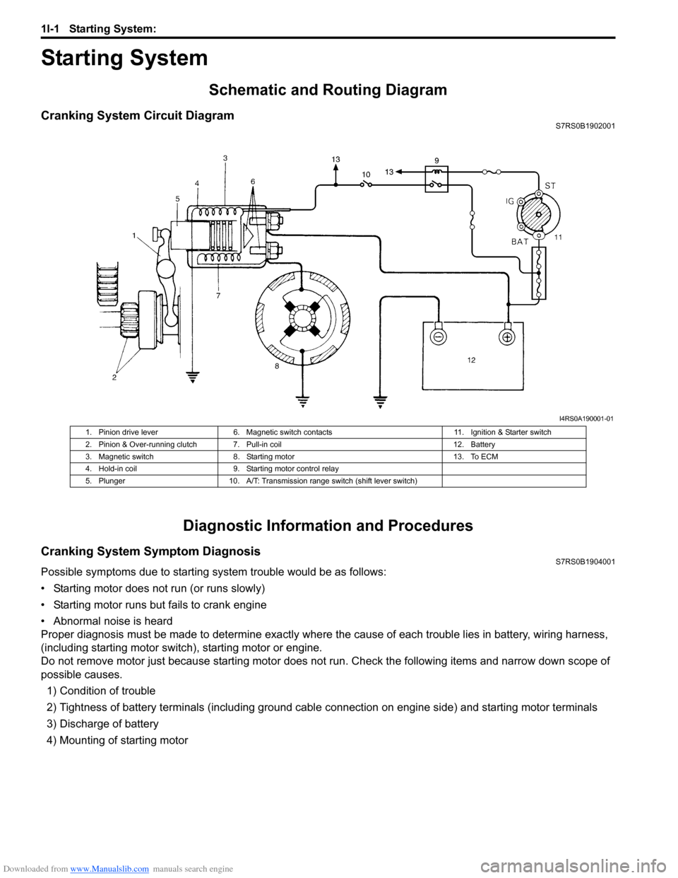
Cranking System Circuit DiagramS7RS0B1902001
Diagnostic Information and Procedures
Cranking System Symptom DiagnosisS7RS0B1904001
Possible symptoms due to starting system trouble would be as follows:
• Starting motor does not run (or runs slowly)
• Starting motor runs but fails to crank engine
• Abnormal noise is heard
Proper diagnosis must be made to determine exactly where the cause of each trouble lies in battery, wiring harness,
(including starting motor switch), starting motor or engine.
Do not remove motor just because starting motor does not run. Check the following items and narrow down scope of
possible causes.
1) Condition of trouble
2) Tightness of battery terminals (including ground cable connection on engine side) and starting motor terminals
3) Discharge of battery
4) Mounting of starting motor
I4RS0A190001-01
1. Pinion drive lever 6. Magnetic switch contacts 11. Ignition & Starter switch
2. Pinion & Over-running clutch 7. Pull-in coil 12. Battery
3. Magnetic switch 8. Starting motor 13. To ECM
4. Hold-in coil 9. Starting motor control relay
5. Plunger 10. A/T: Transmission range switch (shift lever switch)