Gasket SUZUKI SWIFT 2006 2.G Service User Guide
[x] Cancel search | Manufacturer: SUZUKI, Model Year: 2006, Model line: SWIFT, Model: SUZUKI SWIFT 2006 2.GPages: 1496, PDF Size: 34.44 MB
Page 298 of 1496
Downloaded from www.Manualslib.com manuals search engine 1D-13 Engine Mechanical:
Throttle Body On-Vehicle InspectionS7RS0B1406006
Check electric throttle body assembly referring to
“Throttle Valve Operation Check” and “Electric Throttle
Body Assembly Operation Check” under “Electric
Throttle Body Assembly On-Vehicle Inspection in
Section 1C”.
Electric Throttle Body Assembly Removal and
Installation
S7RS0B1406007
CAUTION!
Never disassemble electric throttle body.
Disassembly will spoil its original
performance. If faulty condition is found,
replace it with new one.
NOTE
After replacing electric throttle body
assembly, perform calibration of throttle
valve referring to “Electric Throttle Body
System Calibration in Section 1C”.
Removal
1) Disconnect negative cable at battery.
2) Drain coolant referring to “Cooling System Draining in Section 1F”.
3) Remove air cleaner assembly referring to “Air Cleaner Components”.
4) Detach EVAP canister and purge valve chamber, and remove air cleaner outlet hose.
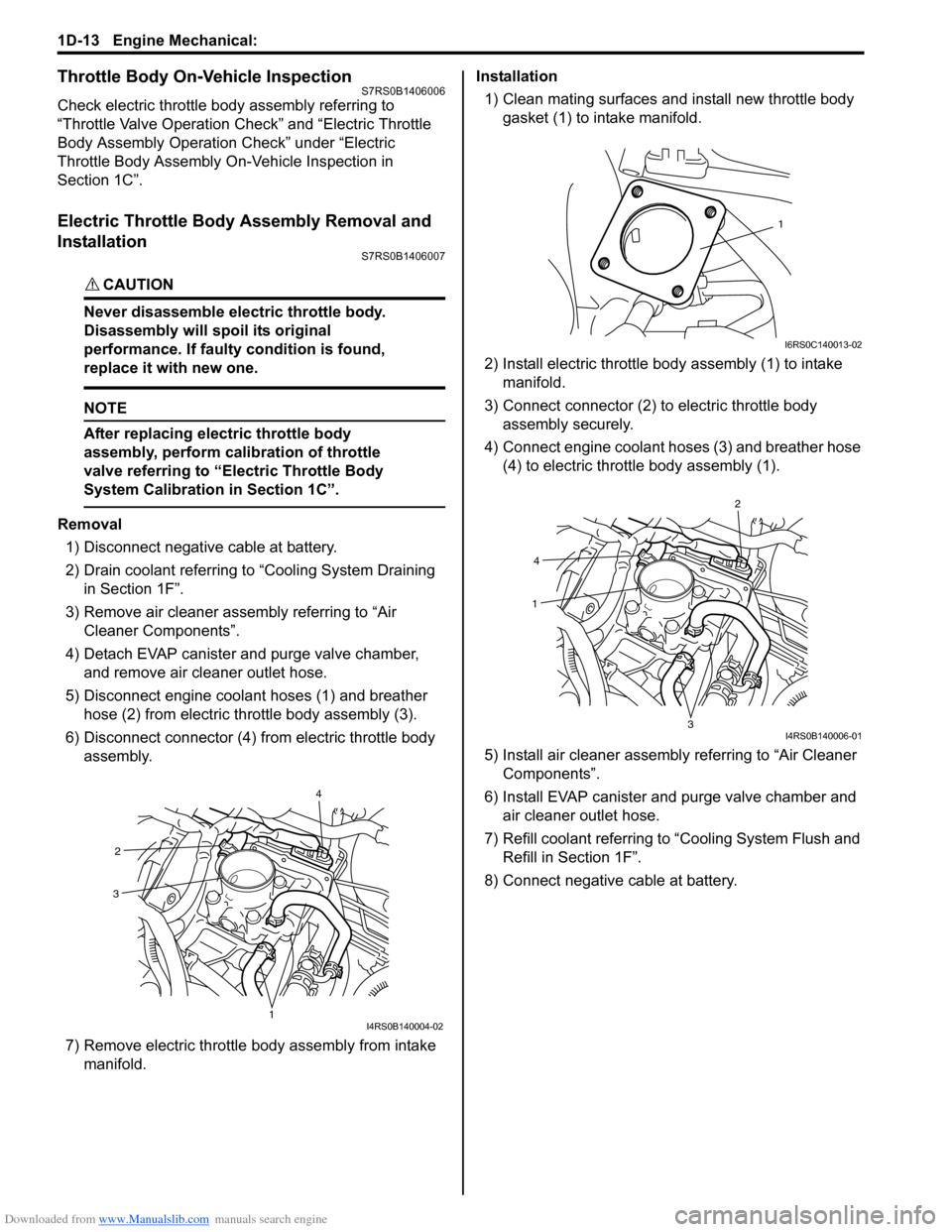
5) Disconnect engine coolant hoses (1) and breather hose (2) from electric throttle body assembly (3).
6) Disconnect connector (4) from electric throttle body assembly.
7) Remove electric throttle body assembly from intake
manifold. Installation
1) Clean mating surfaces and install new throttle body gasket (1) to intake manifold.
2) Install electric throttle bo dy assembly (1) to intake
manifold.
3) Connect connector (2) to electric throttle body assembly securely.
4) Connect engine coolant hoses (3) and breather hose (4) to electric thrott le body assembly (1).
5) Install air cleaner assembly referring to “Air Cleaner
Components”.
6) Install EVAP canister and purge valve chamber and air cleaner outlet hose.
7) Refill coolant referring to “Cooling System Flush and
Refill in Section 1F”.
8) Connect negative cable at battery.
2
4
3
1I4RS0B140004-02
1
I6RS0C140013-02
4
2
1
3I4RS0B140006-01
Page 299 of 1496
Downloaded from www.Manualslib.com manuals search engine Engine Mechanical: 1D-14
Throttle Body CleaningS7RS0B1406008
Clean electric throttle body assembly referring to
“Throttle Valve Visual Check” under “Electric Throttle
Body Assembly On-Vehicle Inspection in Section 1C”.
Intake Manifold Removal and InstallationS7RS0B1406009
Removal1) Remove cowl top plate referring to “Cowl Top Components in Section 9K”.
2) Remove throttle body referring to “Electric Throttle Body Assembly Removal and Installation”.
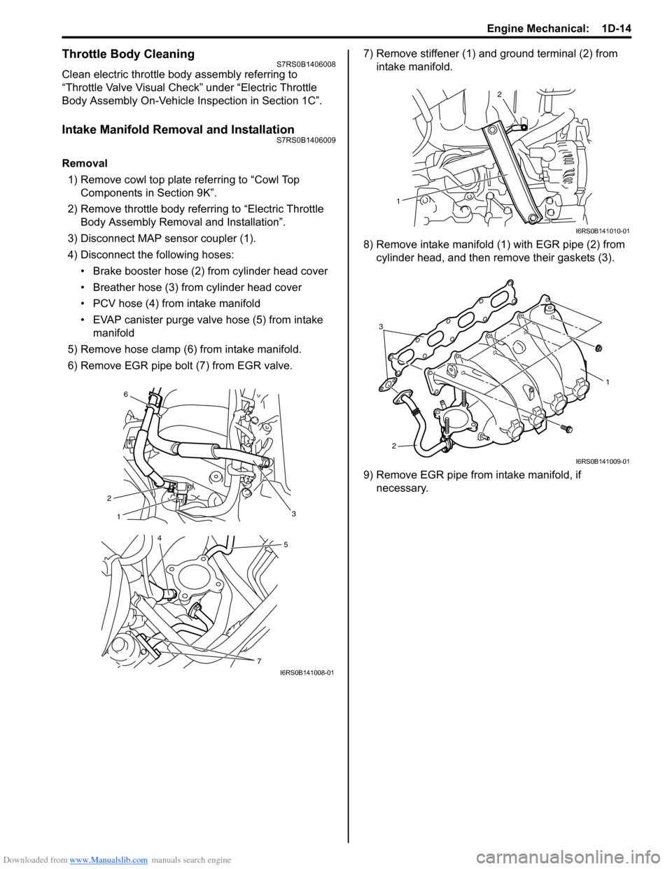
3) Disconnect MAP sensor coupler (1).
4) Disconnect the following hoses: • Brake booster hose (2) from cylinder head cover
• Breather hose (3) from cylinder head cover
• PCV hose (4) from intake manifold
• EVAP canister purge valve hose (5) from intake manifold
5) Remove hose clamp (6) from intake manifold.
6) Remove EGR pipe bolt (7) from EGR valve. 7) Remove stiffener (1) and ground terminal (2) from
intake manifold.
8) Remove intake manifold (1) with EGR pipe (2) from
cylinder head, and then remove their gaskets (3).
9) Remove EGR pipe from intake manifold, if necessary.
6
2 1
3
54
7I6RS0B141008-01
1
2
I6RS0B141010-01
3
2
1
I6RS0B141009-01
Page 300 of 1496
Downloaded from www.Manualslib.com manuals search engine 1D-15 Engine Mechanical:
Installation
Reverse removal procedure for installation noting the
followings.
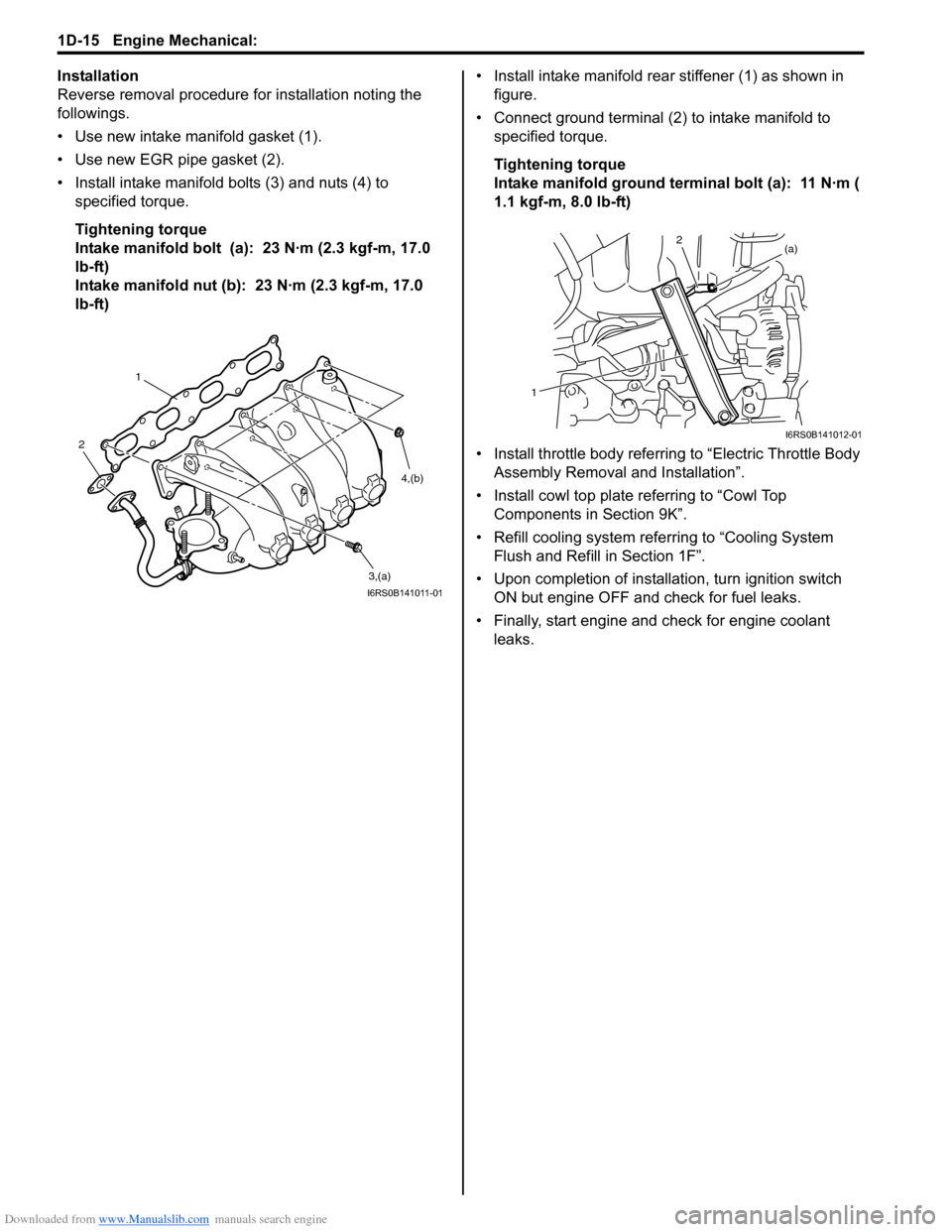
• Use new intake manifold gasket (1).
• Use new EGR pipe gasket (2).
• Install intake manifold bolts (3) and nuts (4) to specified torque.
Tightening torque
Intake manifold bolt (a): 23 N·m (2.3 kgf-m, 17.0
lb-ft)
Intake manifold nut (b): 23 N·m (2.3 kgf-m, 17.0
lb-ft) • Install intake manifold rear stiffener (1) as shown in
figure.
• Connect ground terminal (2) to intake manifold to specified torque.
Tightening torque
Intake manifold ground terminal bolt (a): 11 N·m (
1.1 kgf-m, 8.0 lb-ft)
• Install throttle body referrin g to “Electric Throttle Body
Assembly Removal and Installation”.
• Install cowl top plate referring to “Cowl Top Components in Section 9K”.
• Refill cooling system refe rring to “Cooling System
Flush and Refill in Section 1F”.
• Upon completion of installation, turn ignition switch ON but engine OFF and check for fuel leaks.
• Finally, start engine and check for engine coolant leaks.
1
2
3,(a)
4,(b)
I6RS0B141011-01
(a)
12
I6RS0B141012-01
Page 319 of 1496
Downloaded from www.Manualslib.com manuals search engine Engine Mechanical: 1D-34
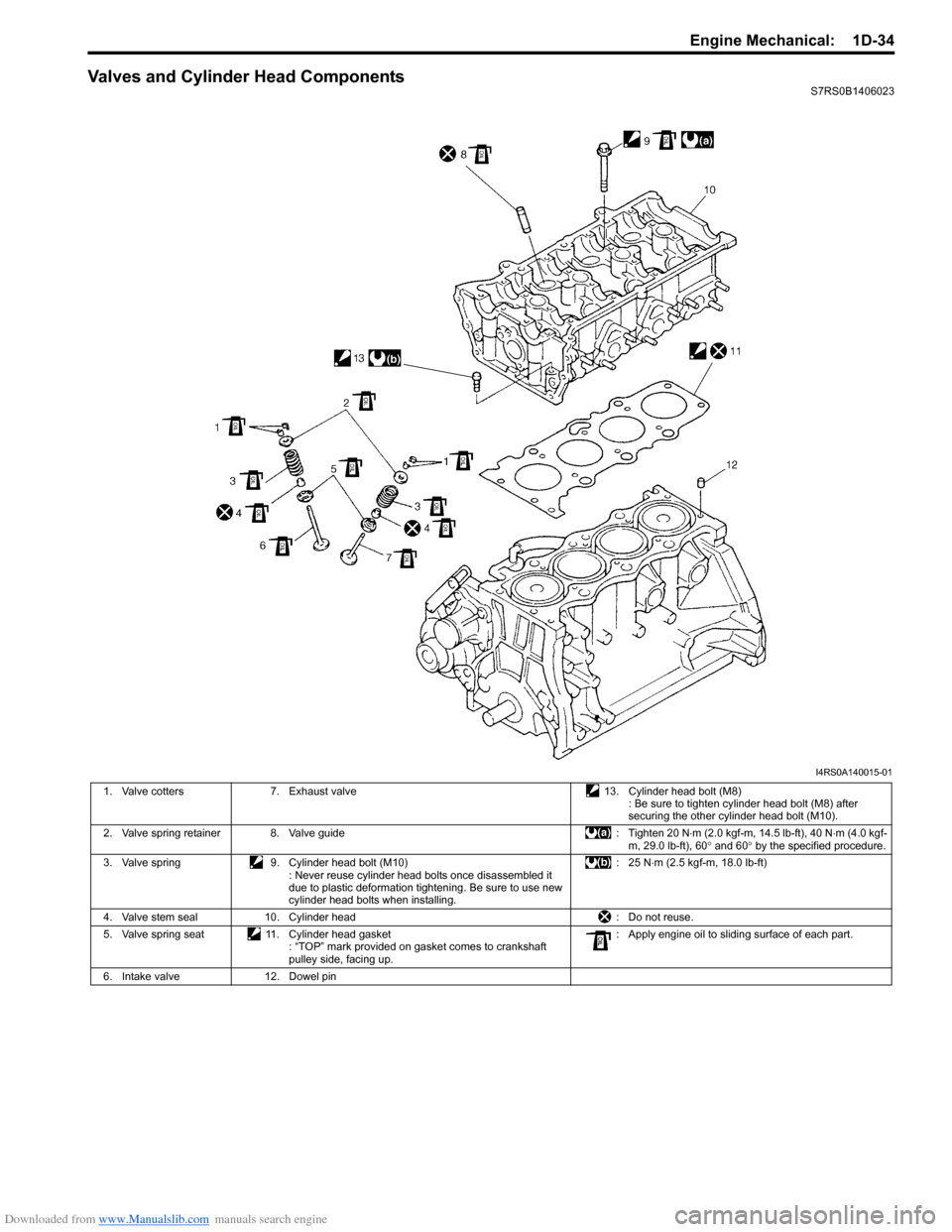
Valves and Cylinder Head ComponentsS7RS0B1406023
I4RS0A140015-01
1. Valve cotters7. Exhaust valve 13. Cylinder head bolt (M8)
: Be sure to tighten cylinder head bolt (M8) after
securing the other cylinder head bolt (M10).
2. Valve spring retainer 8. Valve guide : Tighten 20 N⋅m (2.0 kgf-m, 14.5 lb-ft), 40 N ⋅m (4.0 kgf-
m, 29.0 lb-ft), 60 ° and 60 ° by the specified procedure.
3. Valve spring 9. Cylinder head bolt (M10)
: Never reuse cylinder head bolts once disassembled it
due to plastic deformation tightening. Be sure to use new
cylinder head bolts when installing. : 25 N
⋅m (2.5 kgf-m, 18.0 lb-ft)
4. Valve stem seal 10. Cylinder head : Do not reuse.
5. Valve spring seat 11. Cylinder head gasket
: “TOP” mark provided on gasket comes to crankshaft
pulley side, facing up. : Apply engine oil to sliding surface of each part.
6. Intake valve 12. Dowel pin
Page 320 of 1496
Downloaded from www.Manualslib.com manuals search engine 1D-35 Engine Mechanical:
Valves and Cylinder Head Removal and
Installation
S7RS0B1406024
Removal1) Remove engine assembly from vehicle referring to “Engine Assembly Removal and Installation”.
2) Remove oil pan referring to “Oil Pan and Oil Pump
Strainer Removal and Installation in Section 1E”.
3) Remove cylinder head cover referring to “Cylinder Head Cover Removal and Installation”.
4) Remove timing chain cover referring to Steps 2) to 11) of “Removal” in “Tim ing Chain Cover Removal
and Installation”.
5) Remove timing chain referring to Steps 2) to 6) of “Removal” in “Timing Chain and Chain Tensioner
Removal and Installation”.
6) Remove intake and exhaust camshafts referring to Steps 3) to 8) of “Removal” in “Camshaft, Tappet and
Shim Removal and Installation”.
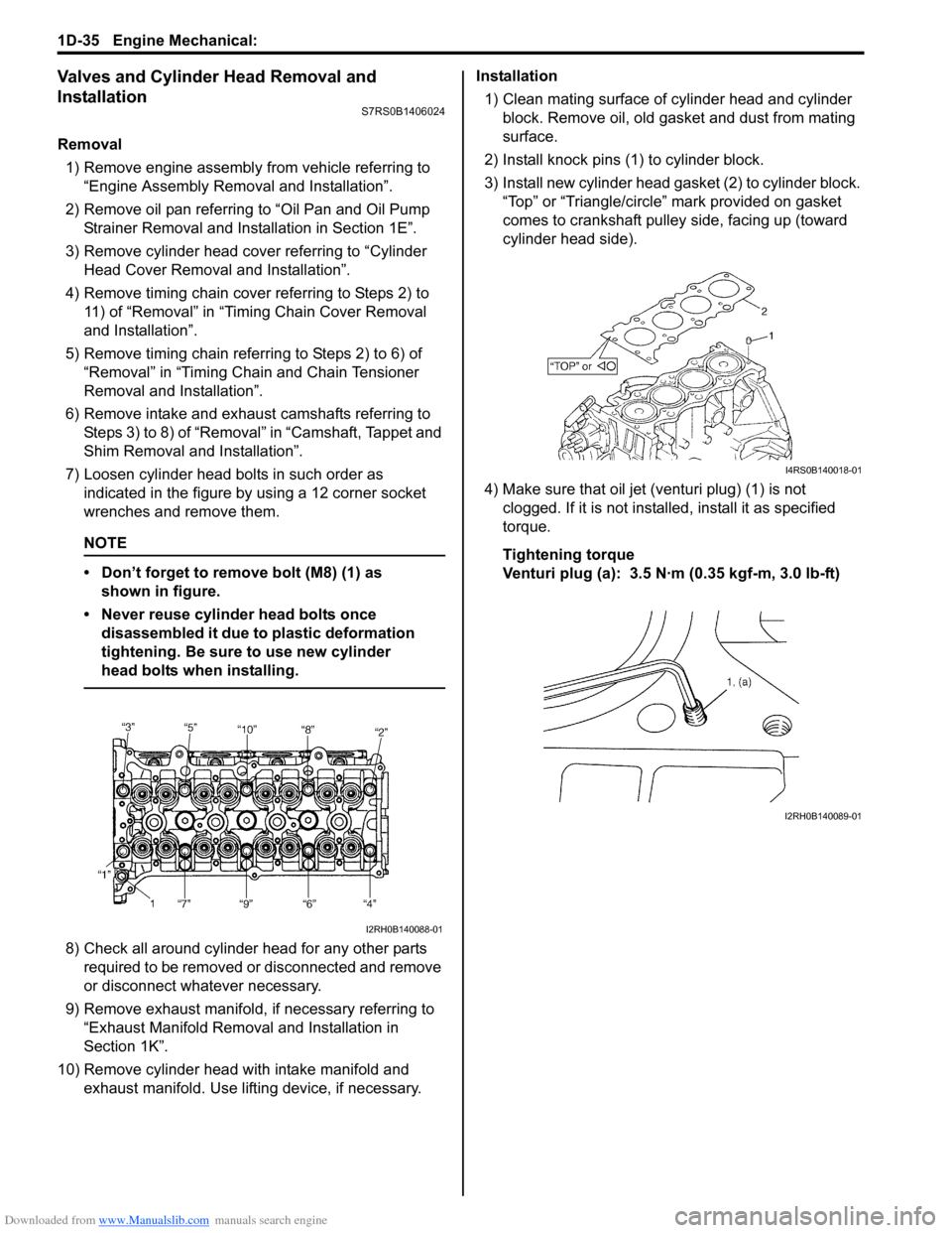
7) Loosen cylinder head bolts in such order as indicated in the figure by using a 12 corner socket
wrenches and remove them.
NOTE
• Don’t forget to remove bolt (M8) (1) as shown in figure.
• Never reuse cylinder head bolts once disassembled it due to plastic deformation
tightening. Be sure to use new cylinder
head bolts when installing.
8) Check all around cylinder head for any other parts required to be removed or disconnected and remove
or disconnect whatever necessary.
9) Remove exhaust manifold, if necessary referring to
“Exhaust Manifold Removal and Installation in
Section 1K”.
10) Remove cylinder head wi th intake manifold and
exhaust manifold. Use lifting device, if necessary. Installation
1) Clean mating surface of cylinder head and cylinder block. Remove oil, old gasket and dust from mating
surface.
2) Install knock pins (1) to cylinder block.
3) Install new cylinder head gasket (2) to cylinder block. “Top” or “Triangle/circle” mark provided on gasket
comes to crankshaft pulley side, facing up (toward
cylinder head side).
4) Make sure that oil jet (venturi plug) (1) is not clogged. If it is not install ed, install it as specified
torque.
Tightening torque
Venturi plug (a): 3.5 N·m (0.35 kgf-m, 3.0 lb-ft)
I2RH0B140088-01
I4RS0B140018-01
I2RH0B140089-01
Page 327 of 1496
Downloaded from www.Manualslib.com manuals search engine Engine Mechanical: 1D-42
Cylinder Head InspectionS7RS0B1406027
• Remove all carbon deposits from combustion chambers.
NOTE
Do not use any sharp-edged tool to scrape
off carbon deposits. Be careful not to scuff or
nick metal surfaces when decarbonizing. The
same applies to valves and valve seats, too.
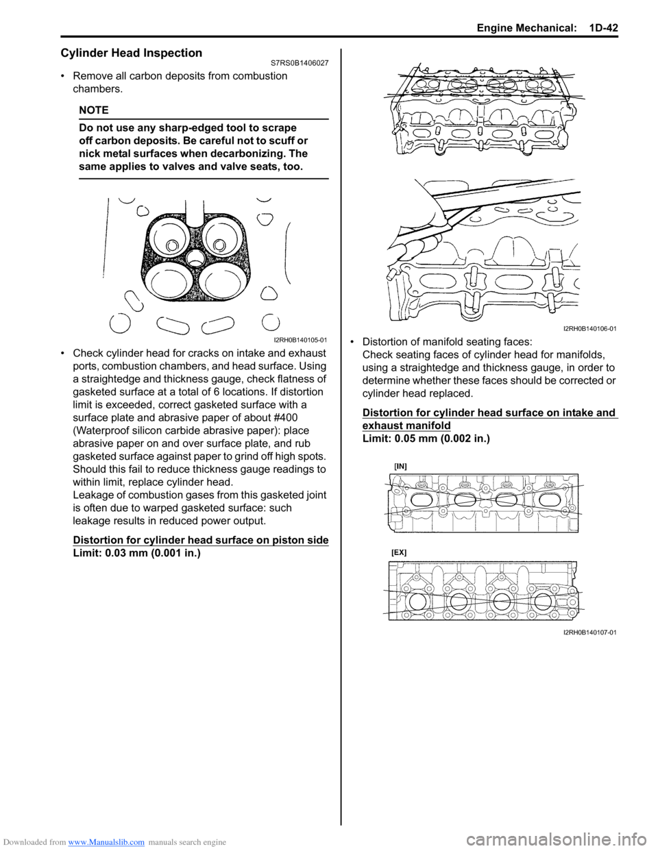
• Check cylinder head for cracks on intake and exhaust ports, combustion chambers, and head surface. Using
a straightedge and thickness gauge, check flatness of
gasketed surface at a total of 6 locations. If distortion
limit is exceeded, correct gasketed surface with a
surface plate and abrasive paper of about #400
(Waterproof silicon carbide abrasive paper): place
abrasive paper on and over surface plate, and rub
gasketed surface against paper to grind off high spots.
Should this fail to reduce thickness gauge readings to
within limit, replace cylinder head.
Leakage of combustion gases from this gasketed joint
is often due to warped gasketed surface: such
leakage results in reduced power output.
Distortion for cylinder head surface on piston side
Limit: 0.03 mm (0.001 in.) • Distortion of manifold seating faces:
Check seating faces of cylinder head for manifolds,
using a straightedge and thickness gauge, in order to
determine whether these faces should be corrected or
cylinder head replaced.
Distortion for cylinder head surface on intake and
exhaust manifold
Limit: 0.05 mm (0.002 in.)
I2RH0B140105-01
I2RH0B140106-01
I2RH0B140107-01
Page 348 of 1496
Downloaded from www.Manualslib.com manuals search engine 1D-63 Engine Mechanical:
Main Bearing Cap No.1 Bolt
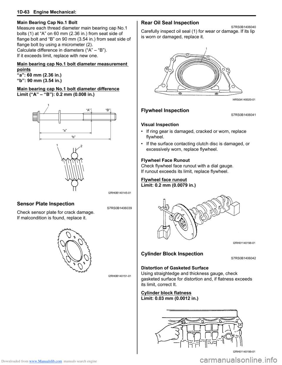
Measure each thread diameter main bearing cap No.1
bolts (1) at “A” on 60 mm (2.36 in.) from seat side of
flange bolt and “B” on 90 mm (3.54 in.) from seat side of
flange bolt by using a micrometer (2).
Calculate difference in diameters (“A” – “B”).
If it exceeds limit, replace with new one.
Main bearing cap No.1 bolt diameter measurement
points
“a”: 60 mm (2.36 in.)
“b”: 90 mm (3.54 in.)
Main bearing cap No.1 bolt diameter difference
Limit (“A” – “B”): 0.2 mm (0.008 in.)
Sensor Plate InspectionS7RS0B1406039
Check sensor plate for crack damage.
If malcondition is found, replace it.
Rear Oil Seal InspectionS7RS0B1406040
Carefully inspect oil seal (1) for wear or damage. If its lip
is worn or damaged, replace it.
Flywheel InspectionS7RS0B1406041
Visual Inspection
• If ring gear is damaged, cracked or worn, replace flywheel.
• If the surface contacting cl utch disc is damaged, or
excessively worn, replace flywheel.
Flywheel Face Runout
Check flywheel face runout with a dial gauge.
If runout exceeds its limit, replace flywheel.
Flywheel face runout
Limit: 0.2 mm (0.0079 in.)
Cylinder Block InspectionS7RS0B1406042
Distortion of Gasketed Surface
Using straightedge and thickness gauge, check
gasketed surface for distortion and, if flatness exceeds
its limit, correct It.
Cylinder block flatness
Limit: 0.03 mm (0.0012 in.)
“A”
“a” “b” “B”
1
1
2
I2RH0B140145-01
I2RH0B140151-01
I4RS0A140020-01
I2RH01140198-01
I2RH01140199-01
Page 355 of 1496
Downloaded from www.Manualslib.com manuals search engine Engine Lubrication System: 1E-3
6) Start engine and warm engine up to normal operating temperature.
NOTE
Be sure to shift transaxle gear shift lever in
“Neutral” (shift select lever in “P” range for
A/T vehicle), set parking brake and block
drive wheels.
7) After warming up, raise engine speed to 4,000 r/min. and measure oil pressure.
Oil pressure specification
More than 270 kPa (2.7 kg/cm2, 39.8 psi) at 4,000
r/min. (rpm)
8) After checking oil pressure, stop engine and remove oil pressure gauge and attachment.
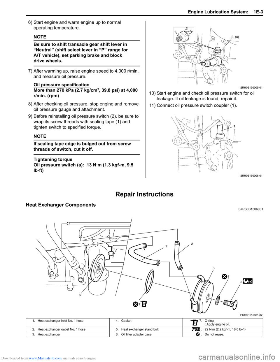
9) Before reinstalling oil pressure switch (2), be sure to
wrap its screw threads with sealing tape (1) and
tighten switch to specified torque.
NOTE
If sealing tape edge is bulged out from screw
threads of switch, cut it off.
Tightening torque
Oil pressure switch (a): 13 N·m (1.3 kgf-m, 9.5
lb-ft) 10) Start engine and check oil pressure switch for oil
leakage. If oil leakage is found, repair it.
11) Connect oil pressure switch coupler (1).
Repair Instructions
Heat Exchanger ComponentsS7RS0B1506001
I2RH0B150005-01
I2RH0B150006-01
3
4
5
7
6
(a)
2
1
I6RS0B151001-02
1. Heat exchanger inlet No. 1 hose 4. Gasket7. O-ring
: Apply engine oil.
2. Heat exchanger outlet No. 1 hose 5. Heat exchanger stand bolt : 22 N⋅m (2.2 kgf-m, 16.0 lb-ft)
3. Heat exchanger 6. Oil filter adapter case : Do not reuse.
Page 356 of 1496
Downloaded from www.Manualslib.com manuals search engine 1E-4 Engine Lubrication System:
Heat Exchanger On-Vehicle InspectionS7RS0B1506002
• Check heat exchanger for deformation wear or damage.
• Check heat exchanger for coolant leakage and oil leakage.
If any malcondition is found, replace O-ring, stand bolt
gasket and/or heat exchanger.
Heat Exchanger Removal and InstallationS7RS0B1506003
Removal
1) Drain engine oil by removing drain plug.
2) Drain coolant referring to “Cooling System Draining in Section 1F”.
3) Remove exhaust manifold referring to “Exhaust Manifold Removal and Inst allation in Section 1K”.
4) Remove heat exchanger inlet No. 1 hose and outlet No. 1 hose.
5) Remove heat exchanger, O-ring and gasket by removing heat exchanger stand bolt. Installation
Reverse removal procedure for installation noting the
followings.
• Use new stand bolt gasket.
• Apply engine oil to new O-ring and install it to heat
exchanger.
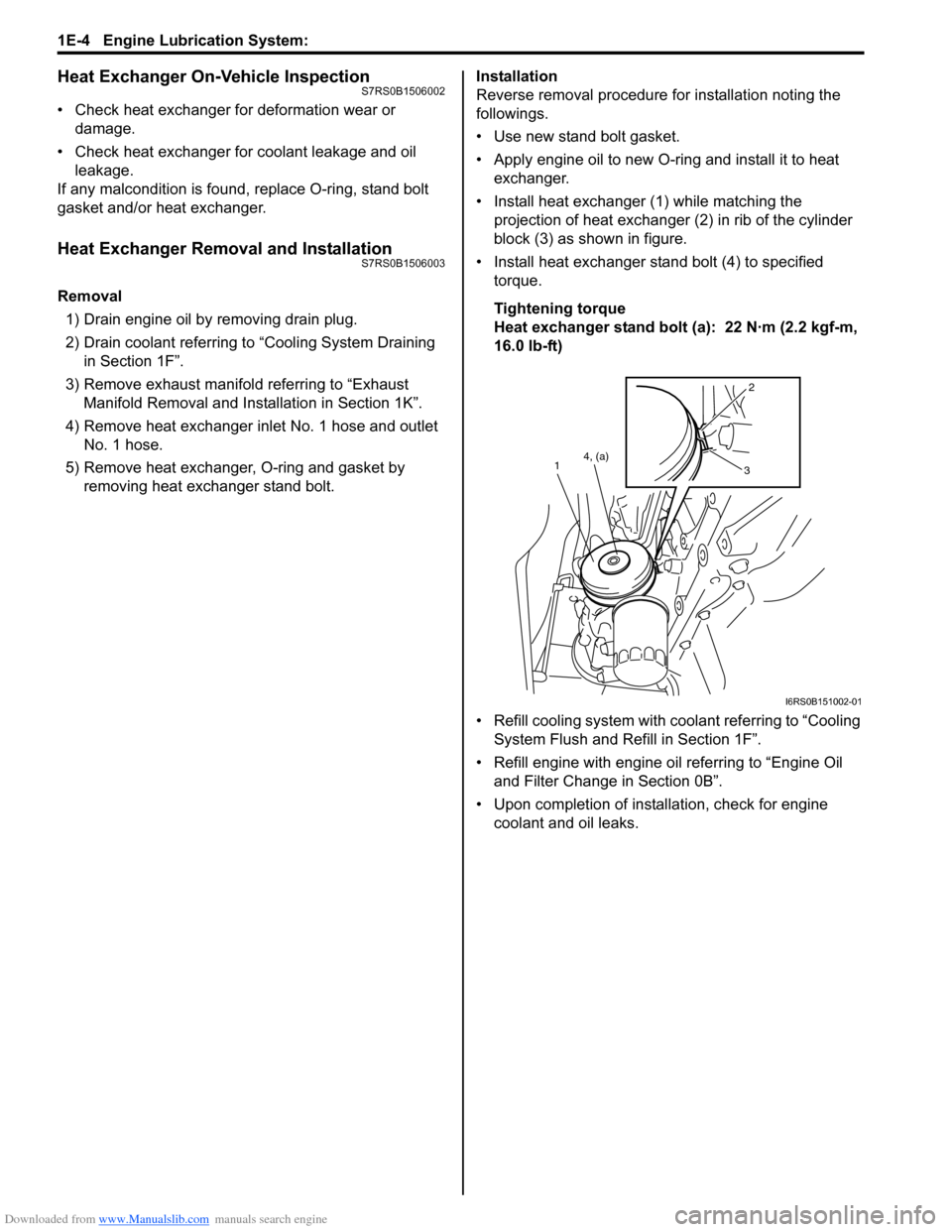
• Install heat exchanger (1) while matching the projection of heat exchanger (2) in rib of the cylinder
block (3) as shown in figure.
• Install heat exchanger stand bolt (4) to specified torque.
Tightening torque
Heat exchanger stand bolt (a): 22 N·m (2.2 kgf-m,
16.0 lb-ft)
• Refill cooling system with co olant referring to “Cooling
System Flush and Refill in Section 1F”.
• Refill engine with engine oil referring to “Engine Oil and Filter Change in Section 0B”.
• Upon completion of installation, check for engine coolant and oil leaks.
2
3
4, (a)
1
I6RS0B151002-01
Page 357 of 1496
Downloaded from www.Manualslib.com manuals search engine Engine Lubrication System: 1E-5
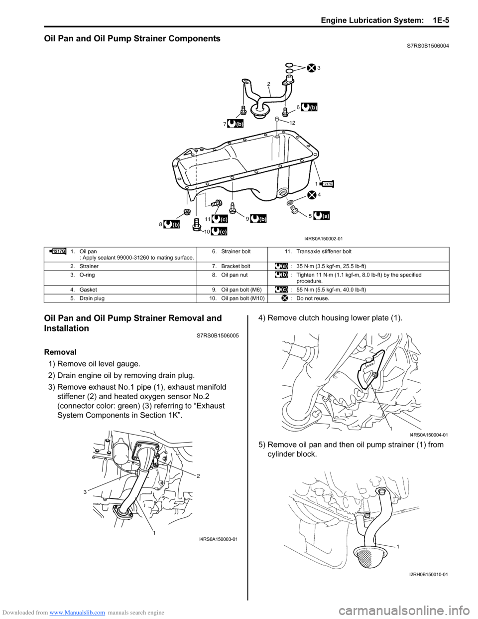
Oil Pan and Oil Pump Strainer ComponentsS7RS0B1506004
Oil Pan and Oil Pump Strainer Removal and
Installation
S7RS0B1506005
Removal1) Remove oil level gauge.
2) Drain engine oil by removing drain plug.
3) Remove exhaust No.1 pipe (1), exhaust manifold stiffener (2) and heated oxygen sensor No.2
(connector color: green) (3) referring to “Exhaust
System Components in Section 1K”. 4) Remove clutch housing lower plate (1).
5) Remove oil pan and then oil pump strainer (1) from
cylinder block.
I4RS0A150002-01
1. Oil pan : Apply sealant 99000-31260 to mating surface. 6. Strainer bolt 11. Transaxle stiffener bolt
2. Strainer 7. Bracket bolt : 35 N ⋅m (3.5 kgf-m, 25.5 lb-ft)
3. O-ring 8. Oil pan nut : Tighten 11 N ⋅m (1.1 kgf-m, 8.0 lb-ft) by the specified
procedure.
4. Gasket 9. Oil pan bolt (M6) : 55 N ⋅m (5.5 kgf-m, 40.0 lb-ft)
5. Drain plug 10. Oil pan bolt (M10) : Do not reuse.
2
1
3
I4RS0A150003-01
1I4RS0A150004-01
I2RH0B150010-01