Starting motor SUZUKI SWIFT 2006 2.G Service User Guide
[x] Cancel search | Manufacturer: SUZUKI, Model Year: 2006, Model line: SWIFT, Model: SUZUKI SWIFT 2006 2.GPages: 1496, PDF Size: 34.44 MB
Page 159 of 1496
Downloaded from www.Manualslib.com manuals search engine Engine General Information and Diagnosis: 1A-109
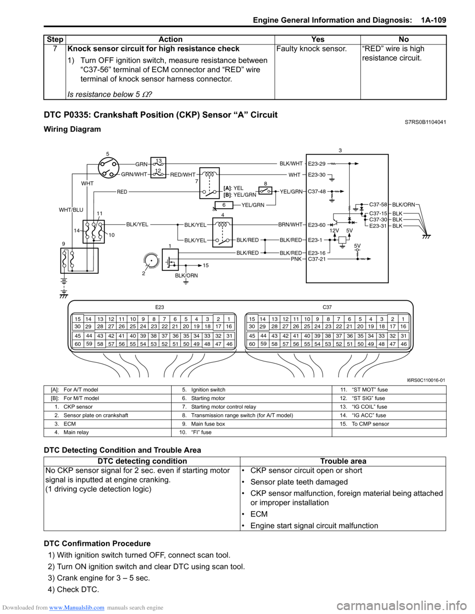
DTC P0335: Crankshaft Position (CKP) Sensor “A” CircuitS7RS0B1104041
Wiring Diagram
DTC Detecting Condition and Trouble Area
DTC Confirmation Procedure1) With ignition switch turned OFF, connect scan tool.
2) Turn ON ignition switch and clear DTC using scan tool.
3) Crank engine for 3 – 5 sec.
4) Check DTC. 7
Knock sensor circuit for high resistance check
1) Turn OFF ignition switch, measure resistance between
“C37-56” terminal of ECM connector and “RED” wire
terminal of knock sensor harness connector.
Is resistance below 5
Ω? Faulty knock sensor. “RED” wire is high
resistance circuit.
Step
Action YesNo
E23 C37
34
1819
567
1011
17
20
47 46
495051
2122
52 16
25 9
24
14
29
55
57 54 53
59
60 58 2
262728
15
30
56 4832 31
34353637
40
42 39 38
44
45 43 41 331
1213
238
34
1819
567
1011
17
20
47 46
495051
2122
52 16
25 9
24
14
29
55
57 54 53
59
60 58 2
262728
15
30
56 4832 31
34353637
40
42 39 38
44
45 43 41 331
1213
238
12V
5V
BLK/RED
BLK/RED
BLK/YELBLK/YEL
BLK/YEL
BRN/WHT
5
9 4
13
3
C37-30C37-15
C37-58
E23-31
BLK/ORN
BLKBLKBLK
10
BLK/RED
BLK/RED
E23-16
E23-60
E23-1
BLK/ORN
1
15
C37-21 5V
7RED/WHTGRN/WHT
GRN
RED
BLK/WHT
YEL/GRN
YEL/GRN
WHT
[A]: YEL
[B]: YEL/GRN
68
12
11
14
PNK
2
WHT
WHT/BLU
C37-48
E23-30
E23-29
I6RS0C110016-01
[A]: For A/T model 5. Ignition switch 11. “ST MOT” fuse
[B]: For M/T model 6. Starting motor 12. “ST SIG” fuse
1. CKP sensor 7. Starting motor control relay 13. “IG COIL” fuse
2. Sensor plate on crankshaft 8. Transmission range switch (for A/T model) 14. “IG ACC” fuse
3. ECM 9. Main fuse box 15. To CMP sensor
4. Main relay 10. “FI” fuse
DTC detecting condition Trouble area
No CKP sensor signal for 2 se c. even if starting motor
signal is inputted at engine cranking.
(1 driving cycle detection logic) • CKP sensor circuit open or short
• Sensor plate teeth damaged
• CKP sensor malfunction, foreign material being attached
or improper installation
•ECM
• Engine start signal circuit malfunction
Page 161 of 1496
Downloaded from www.Manualslib.com manuals search engine Engine General Information and Diagnosis: 1A-111
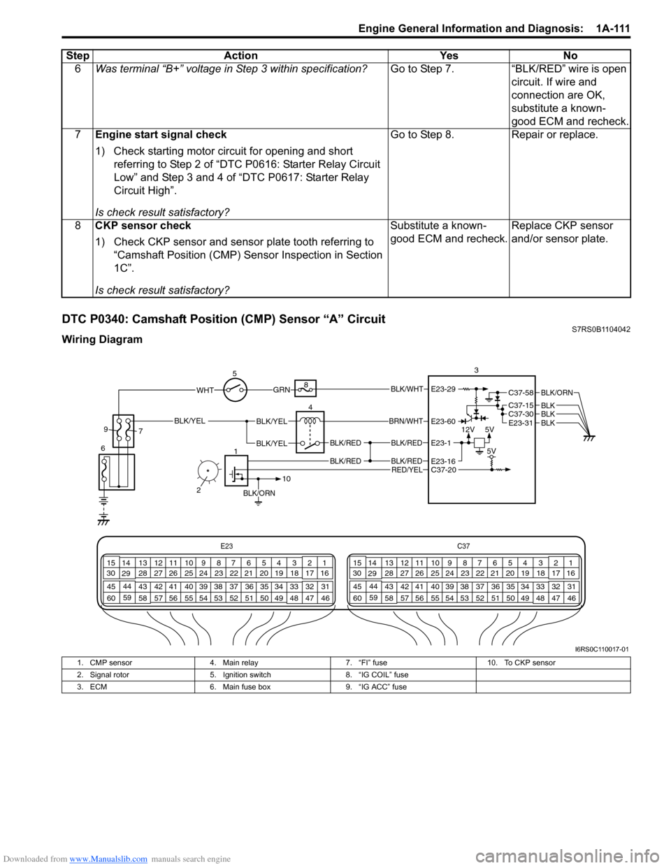
DTC P0340: Camshaft Position (CMP) Sensor “A” CircuitS7RS0B1104042
Wiring Diagram6
Was terminal “B+” voltage in Step 3 within specification? Go to Step 7. “BLK/RED” wire is open
circuit. If wire and
connection are OK,
substitute a known-
good ECM and recheck.
7 Engine start signal check
1) Check starting motor circuit for opening and short
referring to Step 2 of “DTC P0616: Starter Relay Circuit
Low” and Step 3 and 4 of “DTC P0617: Starter Relay
Circuit High”.
Is check result satisfactory? Go to Step 8. Repair or replace.
8 CKP sensor check
1) Check CKP sensor and sensor plate tooth referring to
“Camshaft Position (CMP) Sensor Inspection in Section
1C”.
Is check result satisfactory? Substitute a known-
good ECM and recheck.
Replace CKP sensor
and/or sensor plate.
Step Action Yes No
E23
C37
34
1819
567
1011
17
20
47 46
495051
2122
52 16
25 9
24
14
29
55
57 54 53
59
60 58 2
262728
15
30
56 4832 31
34353637
40
42 39 38
44
45 43 41 331
1213
238
34
1819
567
1011
17
20
47 46
495051
2122
52 16
25 9
24
14
29
55
57 54 53
59
60 58 2
262728
15
30
56 4832 31
34353637
40
42 39 38
44
45 43 41 331
1213
238
12V
5V
BLK/RED
BLK/RED
BLK/YELBLK/YEL
BLK/YEL
BRN/WHT
5
6 4
8
3
C37-30C37-15
C37-58
E23-31
BLK/ORN
BLKBLKBLK
BLK/RED
BLK/RED
E23-16
E23-60
E23-1
BLK/ORN
1
10
C37-20 5V
GRNBLK/WHT
9
7
RED/YEL
2
WHTE23-29
I6RS0C110017-01
1. CMP sensor 4. Main relay 7. “FI” fuse 10. To CKP sensor
2. Signal rotor 5. Ignition switch 8. “IG COIL” fuse
3. ECM 6. Main fuse box 9. “IG ACC” fuse
Page 185 of 1496
Downloaded from www.Manualslib.com manuals search engine Engine General Information and Diagnosis: 1A-135
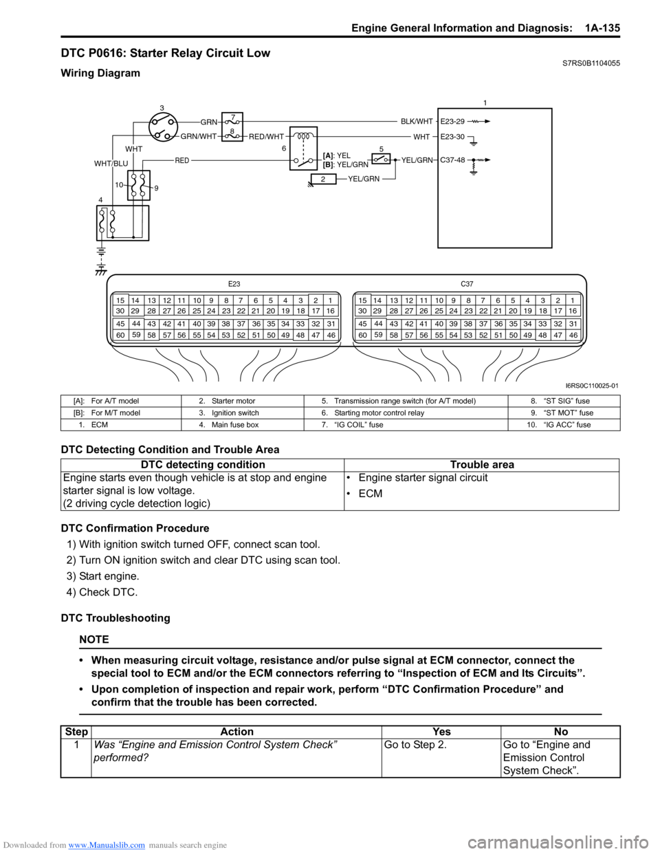
DTC P0616: Starter Relay Circuit LowS7RS0B1104055
Wiring Diagram
DTC Detecting Condition and Trouble Area
DTC Confirmation Procedure1) With ignition switch turned OFF, connect scan tool.
2) Turn ON ignition switch and clear DTC using scan tool.
3) Start engine.
4) Check DTC.
DTC Troubleshooting
NOTE
• When measuring circuit voltage, resistance and/ or pulse signal at ECM connector, connect the
special tool to ECM and/or the ECM connectors re ferring to “Inspection of ECM and Its Circuits”.
• Upon completion of inspection and repair work, perform “DTC Confirmation Procedure” and confirm that the trouble has been corrected.
E23 C37
34
1819
567
1011
17
20
47 46
495051
2122
52 16
25 9
24
14
29
55
57 54 53
59
60 58 2
262728
15
30
56 4832 31
34353637
40
42 39 38
44
45 43 41 331
1213
238
34
1819
567
1011
17
20
47 46
495051
2122
52 16
25 9
24
14
29
55
57 54 53
59
60 58 2
262728
15
30
56 4832 31
34353637
40
42 39 38
44
45 43 41 331
1213
238
3
4 7
1
6
RED/WHTGRN/WHT
GRN
RED
BLK/WHT
YEL/GRN
YEL/GRN
WHT
[A]: YEL
[B]: YEL/GRN
25
8
9
10
WHT
WHT/BLUC37-48
E23-30
E23-29
I6RS0C110025-01
[A]: For A/T model
2. Starter motor5. Transmission range switch (for A/T model) 8. “ST SIG” fuse
[B]: For M/T model 3. Ignition switch6. Starting motor control relay 9. “ST MOT” fuse
1. ECM 4. Main fuse box 7. “IG COIL” fuse 10. “IG ACC” fuse
DTC detecting condition Trouble area
Engine starts even though vehicle is at stop and engine
starter signal is low voltage.
(2 driving cycle detection logic) • Engine starter signal circuit
•ECM
Step
Action YesNo
1 Was “Engine and Emission Control System Check”
performed? Go to Step 2.
Go to “Engine and
Emission Control
System Check”.
Page 187 of 1496
Downloaded from www.Manualslib.com manuals search engine Engine General Information and Diagnosis: 1A-137
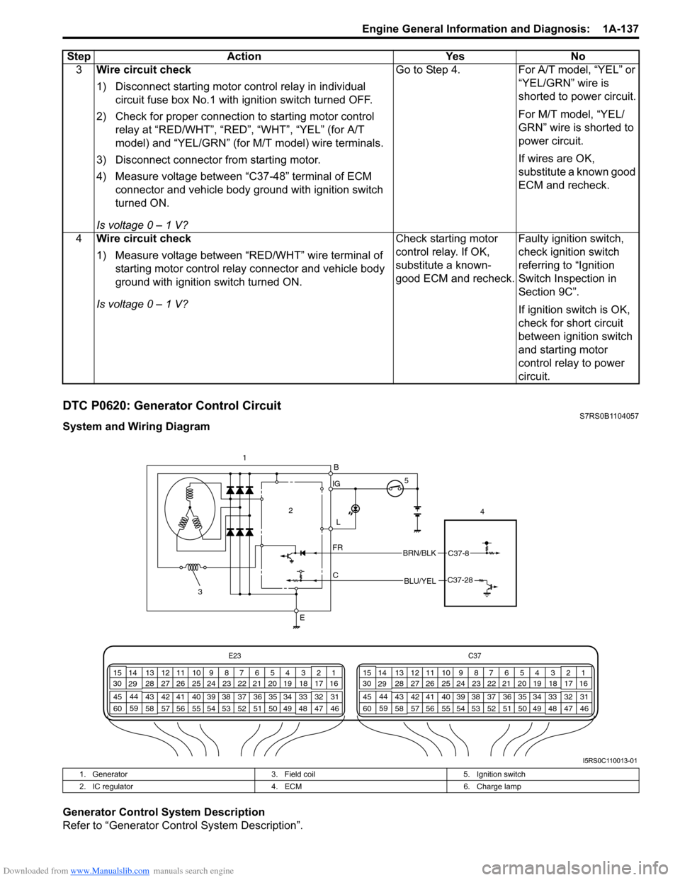
DTC P0620: Generator Control CircuitS7RS0B1104057
System and Wiring Diagram
Generator Control System Description
Refer to “Generator Control System Description”.3
Wire circuit check
1) Disconnect starting motor control relay in individual
circuit fuse box No.1 with ignition switch turned OFF.
2) Check for proper connection to starting motor control relay at “RED/WHT”, “RED”, “WHT”, “YEL” (for A/T
model) and “YEL/GRN” (for M/T model) wire terminals.
3) Disconnect connector from starting motor.
4) Measure voltage between “C37-48” terminal of ECM connector and vehicle body ground with ignition switch
turned ON.
Is voltage 0 – 1 V? Go to Step 4. For A/T model, “YEL” or
“YEL/GRN” wire is
shorted to power circuit.
For M/T model, “YEL/
GRN” wire is shorted to
power circuit.
If wires are OK,
substitute a known good
ECM and recheck.
4 Wire circuit check
1) Measure voltage between “RED/WHT” wire terminal of
starting motor control relay connector and vehicle body
ground with ignition switch turned ON.
Is voltage 0 – 1 V? Check starting motor
control relay. If OK,
substitute a known-
good ECM and recheck.
Faulty ignition switch,
check ignition switch
referring to “Ignition
Switch Inspection in
Section 9C”.
If ignition switch is OK,
check for short circuit
between ignition switch
and starting motor
control relay to power
circuit.
Step Action Yes No
IG
L
C
FR
E 4
2
BRN/BLKC37-8
BLU/YELC37-28
B
E23
C37
34
1819
567
1011
17
20
47 46
495051
2122
52 16
25 9
24
14
29
55
57 54 53
59
60 58 2
262728
15
30
56 4832 31
34353637
40
42 39 38
44
45 43 41 331
1213
238
34
1819
567
1011
17
20
47 46
495051
2122
52 16
25 9
24
14
29
55
57 54 53
59
60 58 2
262728
15
30
56 4832 31
34353637
40
42 39 38
44
45 43 41 331
1213
238 1
3 5
I5RS0C110013-01
1. Generator
3. Field coil 5. Ignition switch
2. IC regulator 4. ECM 6. Charge lamp
Page 205 of 1496
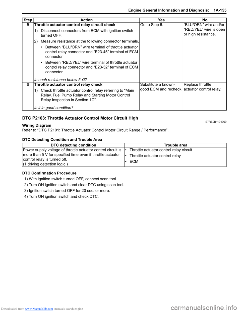
Downloaded from www.Manualslib.com manuals search engine Engine General Information and Diagnosis: 1A-155
DTC P2103: Throttle Actuator Control Motor Circuit HighS7RS0B1104069
Wiring Diagram
Refer to “DTC P2101: Throttle Actuator Control Motor Circuit Range / Performance”.
DTC Detecting Condition and Trouble Area
DTC Confirmation Procedure 1) With ignition switch turned OFF, connect scan tool.
2) Turn ON ignition switch and clear DTC using scan tool.
3) Ignition switch turned OFF for 20 sec. or more.
4) Turn ON ignition switch and check DTC. 5
Throttle actuator cont rol relay circuit check
1) Disconnect connectors from ECM with ignition switch turned OFF.
2) Measure resistance at the following connector terminals. • Between “BLU/ORN” wire termin al of throttle actuator
control relay connector and “E23-45” terminal of ECM
connector
• Between “RED/YEL” wire terminal of throttle actuator control relay connector and “E23-32” terminal of ECM
connector
Is each resistance below 5
Ω? Go to Step 6. “BLU/ORN” wire and/or
“RED/YEL” wire is open
or high resistance.
6 Throttle actuator control relay check
1) Check throttle actuator control relay referring to “Main Relay, Fuel Pump Relay an d Starting Motor Control
Relay Inspection in Section 1C”.
Is it in good condition? Substitute a known-
good ECM and recheck.
Replace throttle
actuator control relay.
Step
Action YesNo
DTC detecting condition Trouble area
Power supply voltage of throttle actuator control circuit is
more than 5 V for specified time even if throttle actuator
control relay is turned off.
(1 driving detection logic.) • Throttle actuator control relay circuit
• Throttle actuator control relay
•ECM
Page 206 of 1496
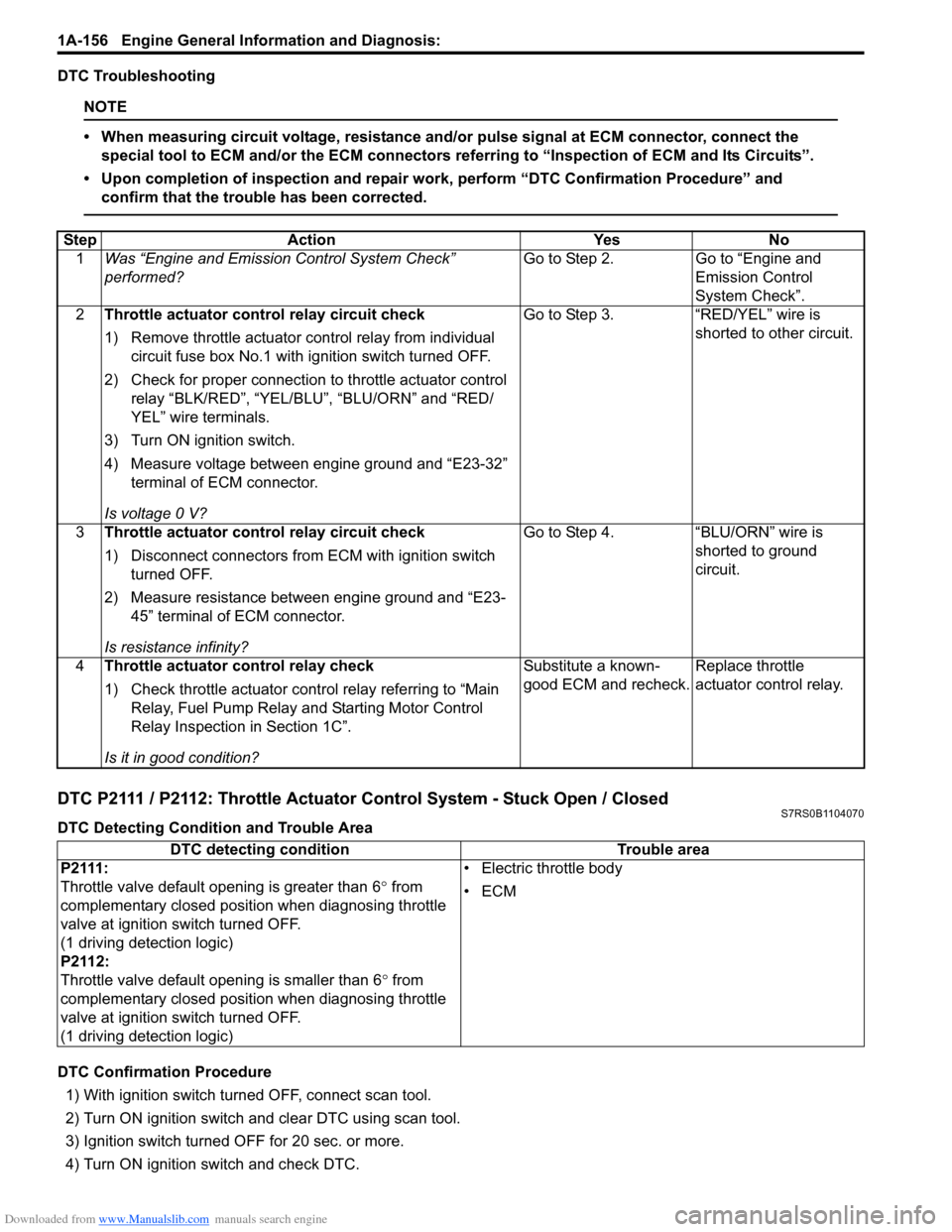
Downloaded from www.Manualslib.com manuals search engine 1A-156 Engine General Information and Diagnosis:
DTC Troubleshooting
NOTE
• When measuring circuit voltage, resistance and/or pulse signal at ECM connector, connect the
special tool to ECM and/or the ECM connectors re ferring to “Inspection of ECM and Its Circuits”.
• Upon completion of inspection and repair work, perform “DTC Confirmation Procedure” and confirm that the trouble has been corrected.
DTC P2111 / P2112: Throttle Actuator Control System - Stuck Open / ClosedS7RS0B1104070
DTC Detecting Condition and Trouble Area
DTC Confirmation Procedure
1) With ignition switch turned OFF, connect scan tool.
2) Turn ON ignition switch and clear DTC using scan tool.
3) Ignition switch turned OFF for 20 sec. or more.
4) Turn ON ignition switch and check DTC.
Step Action Yes No
1 Was “Engine and Emission Control System Check”
performed? Go to Step 2. Go to “Engine and
Emission Control
System Check”.
2 Throttle actuator cont rol relay circuit check
1) Remove throttle actuator co ntrol relay from individual
circuit fuse box No.1 with ignition switch turned OFF.
2) Check for proper connection to throttle actuator control relay “BLK/RED”, “YEL/BLU”, “BLU/ORN” and “RED/
YEL” wire terminals.
3) Turn ON ignition switch.
4) Measure voltage between engine ground and “E23-32” terminal of ECM connector.
Is voltage 0 V? Go to Step 3. “RED/YEL” wire is
shorted to other circuit.
3 Throttle actuator cont rol relay circuit check
1) Disconnect connectors from ECM with ignition switch turned OFF.
2) Measure resistance between engine ground and “E23- 45” terminal of ECM connector.
Is resistance infinity? Go to Step 4. “BLU/ORN” wire is
shorted to ground
circuit.
4 Throttle actuator control relay check
1) Check throttle actuator control relay referring to “Main Relay, Fuel Pump Relay an d Starting Motor Control
Relay Inspection in Section 1C”.
Is it in good condition? Substitute a known-
good ECM and recheck.
Replace throttle
actuator control relay.
DTC detecting condition
Trouble area
P2111:
Throttle valve default opening is greater than 6 ° from
complementary closed position when diagnosing throttle
valve at ignition switch turned OFF.
(1 driving detection logic)
P2112:
Throttle valve default opening is smaller than 6 ° from
complementary closed position when diagnosing throttle
valve at ignition switch turned OFF.
(1 driving detection logic) • Electric throttle body
•ECM
Page 229 of 1496
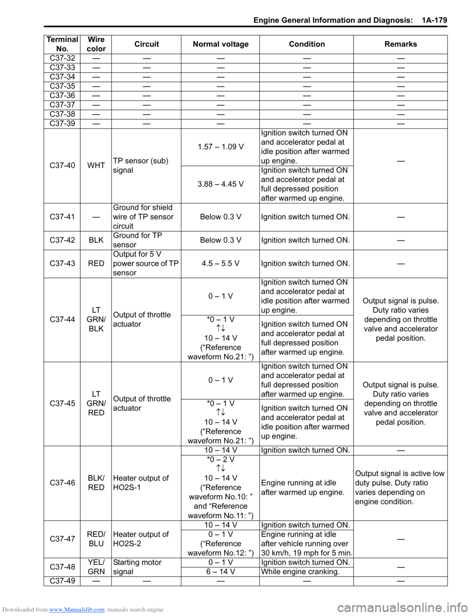
Downloaded from www.Manualslib.com manuals search engine Engine General Information and Diagnosis: 1A-179
C37-32 ——— — —
C37-33 — —— — —
C37-34 — —— — —
C37-35 — —— — —
C37-36 — —— — —
C37-37 — —— — —
C37-38 — —— — —
C37-39 — —— — —
C37-40 WHT TP sensor (sub)
signal 1.57 – 1.09 V
Ignition switch turned ON
and accelerator pedal at
idle position after warmed
up engine.
—
3.88 – 4.45 V Ignition switch turned ON
and accelerator pedal at
full depressed position
after warmed up engine.
C37-41 — Ground for shield
wire of TP sensor
circuit Below 0.3 V Ignition switch turned ON.
—
C37-42 BLK Ground for TP
sensor Below 0.3 V Ignition switch turned ON.
—
C37-43 RED Output for 5 V
power source of TP
sensor 4.5 – 5.5 V Ignition switch turned ON.
—
C37-44 LT
GRN/ BLK Output of throttle
actuator 0 – 1 V
Ignition switch turned ON
and accelerator pedal at
idle position after warmed
up engine.
Output signal is pulse.
Duty ratio varies
depending on throttle
valve and accelerator pedal position.
*0 – 1 V
↑↓
10 – 14 V
(“Reference
waveform No.21: ”) Ignition switch turned ON
and accelerator pedal at
full depressed position
after warmed up engine.
C37-45 LT
GRN/ RED Output of throttle
actuator 0 – 1 V
Ignition switch turned ON
and accelerator pedal at
full depressed position
after warmed up engine.
Output signal is pulse.
Duty ratio varies
depending on throttle
valve and accelerator pedal position.
*0 – 1 V
↑↓
10 – 14 V
(“Reference
waveform No.21: ”) Ignition switch turned ON
and accelerator pedal at
idle position after warmed
up engine.
C37-46 BLK/
RED Heater output of
HO2S-1 10 – 14 V Ignition switch turned ON.
—
*0 – 2 V ↑↓
10 – 14 V
(“Reference
waveform No.10: ” and “Reference
waveform No.11: ”) Engine running at idle
after warmed up engine.
Output signal is active low
duty pulse. Duty ratio
varies depending on
engine condition.
C37-47 RED/
BLU Heater output of
HO2S-2 10 – 14 V Ignition switch turned ON.
—
0 – 1 V
(“Reference
waveform No.12: ”) Engine running at idle
after vehicle running over
30 km/h, 19 mph for 5 min.
C37-48 YEL/
GRN Starting motor
signal 0 – 1 V Ignition switch turned ON.
—
6 – 14 V While engine cranking.
C37-
49 — —— — —
Terminal
No. Wire
color Circuit Normal voltage
ConditionRemarks
Page 232 of 1496
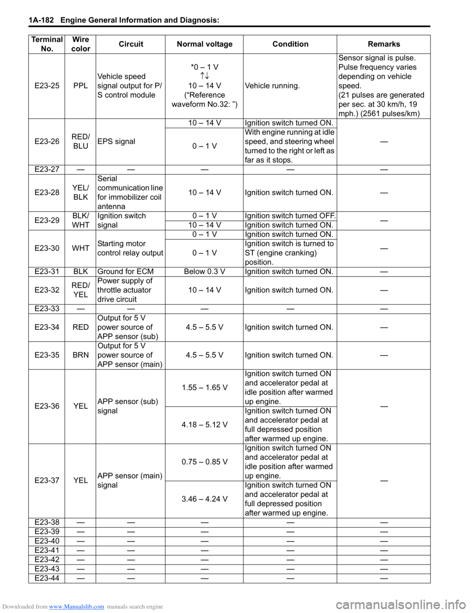
Downloaded from www.Manualslib.com manuals search engine 1A-182 Engine General Information and Diagnosis:
E23-25 PPLVehicle speed
signal output for P/
S control module *0 – 1 V
↑↓
10 – 14 V
(“Reference
waveform No.32: ”) Vehicle running. Sensor signal is pulse.
Pulse frequency varies
depending on vehicle
speed.
(21 pulses are generated
per sec. at 30 km/h, 19
mph.) (2561 pulses/km)
E23-26 RED/
BLU EPS signal 10 – 14 V Ignition switch turned ON.
—
0 – 1 V With engine running at idle
speed, and steering wheel
turned to the right or left as
far as it stops.
E23-27 — — — — —
E23-28 YEL/
BLK Serial
communication line
for immobilizer coil
antenna
10 – 14 V Ignition switch turned ON. —
E23-29 BLK/
WHT Ignition switch
signal 0 – 1 V Ignition switch turned OFF.
—
10 – 14 V Ignition switch turned ON.
E23-30 WHT Starting motor
control relay output 0 – 1 V Ignition switch turned ON.
—
0 – 1 V Ignition switch is turned to
ST (engine cranking)
position.
E23-31 BLK Ground for ECM Below 0.3 V Ignition switch turned ON. —
E23-32 RED/
YEL Power supply of
throttle actuator
drive circuit
10 – 14 V Ignition switch turned ON. —
E23-33 — — — — —
E23-34 RED Output for 5 V
power source of
APP sensor (sub) 4.5 – 5.5 V Ignition switch turned ON. —
E23-35 BRN Output for 5 V
power source of
APP sensor (main) 4.5 – 5.5 V Ignition switch turned ON. —
E23-36 YEL APP sensor (sub)
signal 1.55 – 1.65 V
Ignition switch turned ON
and accelerator pedal at
idle position after warmed
up engine.
—
4.18 – 5.12 V Ignition switch turned ON
and accelerator pedal at
full depressed position
after warmed up engine.
E23-37 YEL APP sensor (main)
signal 0.75 – 0.85 V
Ignition switch turned ON
and accelerator pedal at
idle position after warmed
up engine.
—
3.46 – 4.24 V Ignition switch turned ON
and accelerator pedal at
full depressed position
after warmed up engine.
E23-38 — — — — —
E23-39 — — — — —
E23-40 — — — — —
E23-41 — — — — —
E23-42 — — — — —
E23-43 — — — — —
E23-44 — — — — —
Terminal
No. Wire
color Circuit Normal voltage Condition Remarks
Page 247 of 1496
Downloaded from www.Manualslib.com manuals search engine Engine General Information and Diagnosis: 1A-197
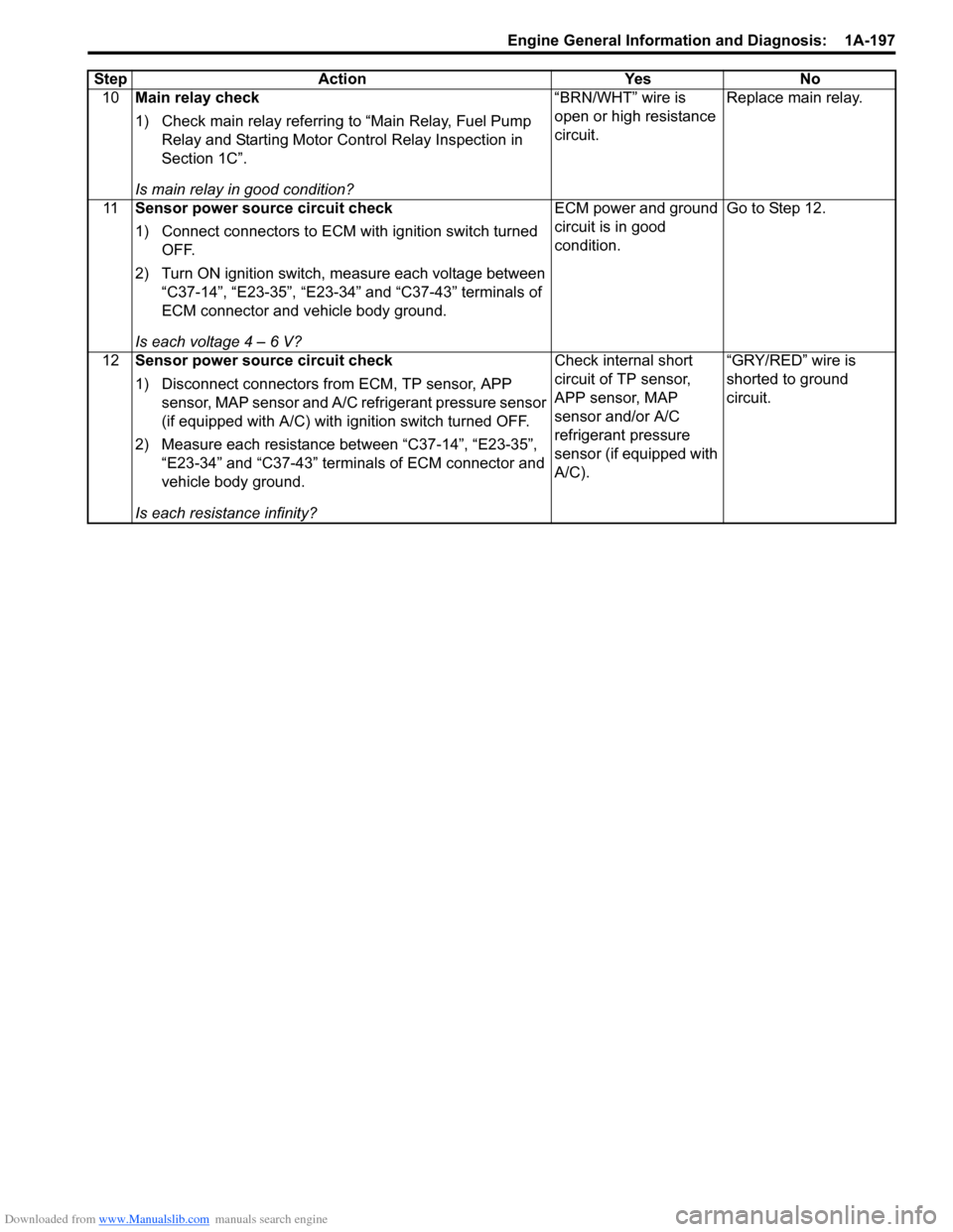
10Main relay check
1) Check main relay referring to “Main Relay, Fuel Pump
Relay and Starting Motor Control Relay Inspection in
Section 1C”.
Is main relay in good condition? “BRN/WHT” wire is
open or high resistance
circuit.
Replace main relay.
11 Sensor power source circuit check
1) Connect connectors to ECM with ignition switch turned
OFF.
2) Turn ON ignition switch, measure each voltage between “C37-14”, “E23-35”, “E23-34” and “C37-43” terminals of
ECM connector and vehicle body ground.
Is each voltage 4 – 6 V? ECM power and ground
circuit is in good
condition.
Go to Step 12.
12 Sensor power source circuit check
1) Disconnect connectors from ECM, TP sensor, APP
sensor, MAP sensor and A/C refrigerant pressure sensor
(if equipped with A/C) with i gnition switch turned OFF.
2) Measure each resistance between “C37-14”, “E23-35”, “E23-34” and “C37-43” terminals of ECM connector and
vehicle body ground.
Is each resistance infinity? Check internal short
circuit of TP sensor,
APP sensor, MAP
sensor and/or A/C
refrigerant pressure
sensor (if equipped with
A/C).
“GRY/RED” wire is
shorted to ground
circuit.
Step Action Yes No
Page 282 of 1496
Downloaded from www.Manualslib.com manuals search engine 1C-10 Engine Electrical Devices:
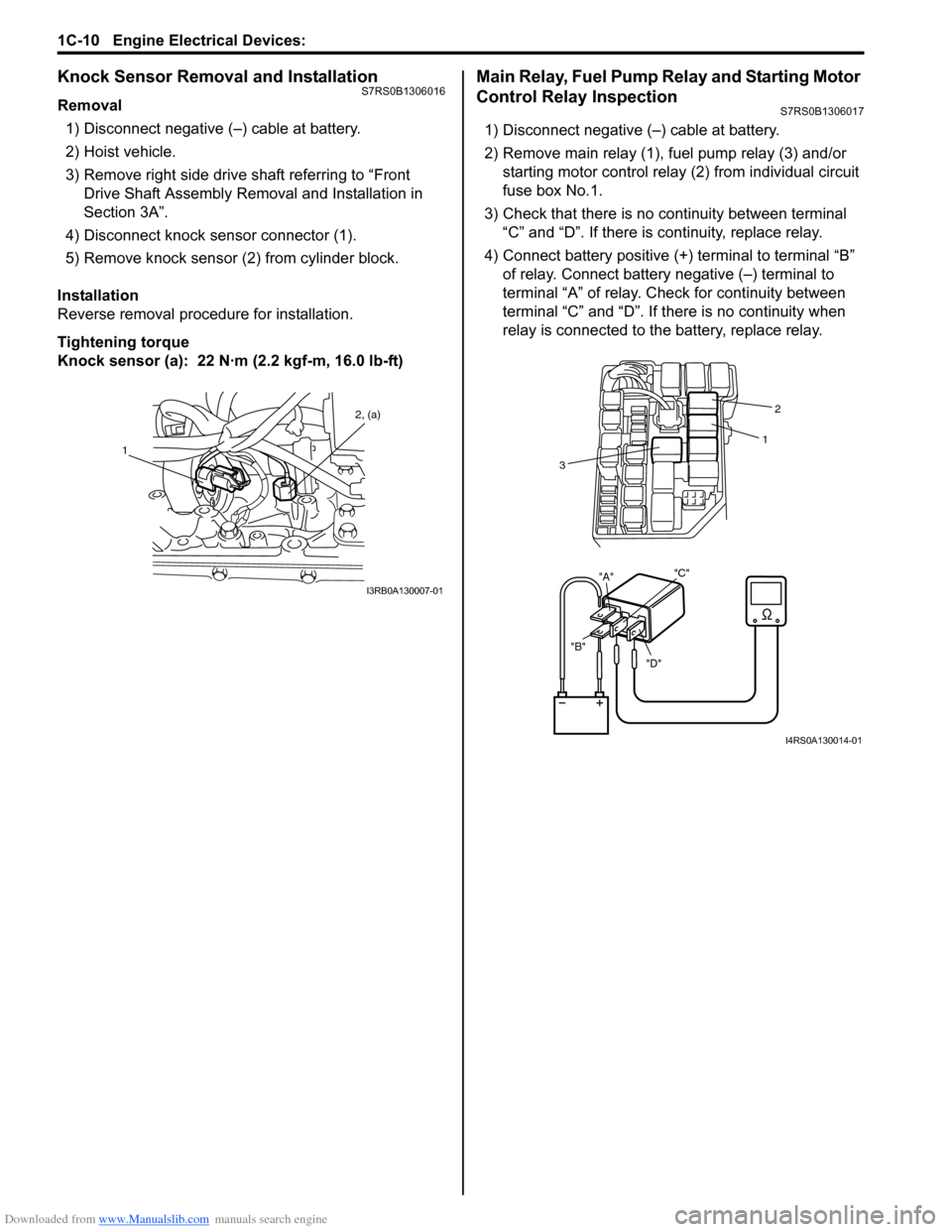
Knock Sensor Removal and InstallationS7RS0B1306016
Removal1) Disconnect negative (–) cable at battery.
2) Hoist vehicle.
3) Remove right side drive shaft referring to “Front Drive Shaft Assembly Removal and Installation in
Section 3A”.
4) Disconnect knock sensor connector (1).
5) Remove knock sensor (2) from cylinder block.
Installation
Reverse removal procedure for installation.
Tightening torque
Knock sensor (a): 22 N· m (2.2 kgf-m, 16.0 lb-ft)
Main Relay, Fuel Pump Relay and Starting Motor
Control Relay Inspection
S7RS0B1306017
1) Disconnect negative (–) cable at battery.
2) Remove main relay (1), fuel pump relay (3) and/or
starting motor control relay (2) from individual circuit
fuse box No.1.
3) Check that there is no continuity between terminal “C” and “D”. If there is continuity, replace relay.
4) Connect battery positive (+ ) terminal to terminal “B”
of relay. Connect battery negative (–) terminal to
terminal “A” of relay. Ch eck for continuity between
terminal “C” and “D”. If t here is no continuity when
relay is connected to the battery, replace relay.
1 2, (a)
I3RB0A130007-01
"D"
"B" "A"
"C"
2
1
3
I4RS0A130014-01