Starting motor SUZUKI SWIFT 2006 2.G Service Owner's Guide
[x] Cancel search | Manufacturer: SUZUKI, Model Year: 2006, Model line: SWIFT, Model: SUZUKI SWIFT 2006 2.GPages: 1496, PDF Size: 34.44 MB
Page 415 of 1496
Downloaded from www.Manualslib.com manuals search engine Charging System: 1J-5
Generator Test (Undercharged Battery Check)S7RS0B1A04003
This condition, as evidenced by slow cranking or
indicator clear with dark or light yellow dot can be
caused by one or more of the following conditions even
though indicator lamp may be operating normal.
The following procedure also applies to cars with
voltmeter and ammeter.1) Make sure that undercharged condition has not been caused by accessories left on for extended period of
time.
2) Check drive belt for proper tension.
3) If battery defect is suspected, refer to “Battery Description”.
4) Inspect wiring for defects. Check all connections for tightness and cleanliness, battery cable connections
at battery, starting motor, ignition ground cable and
no “C” terminal circuit at ground.
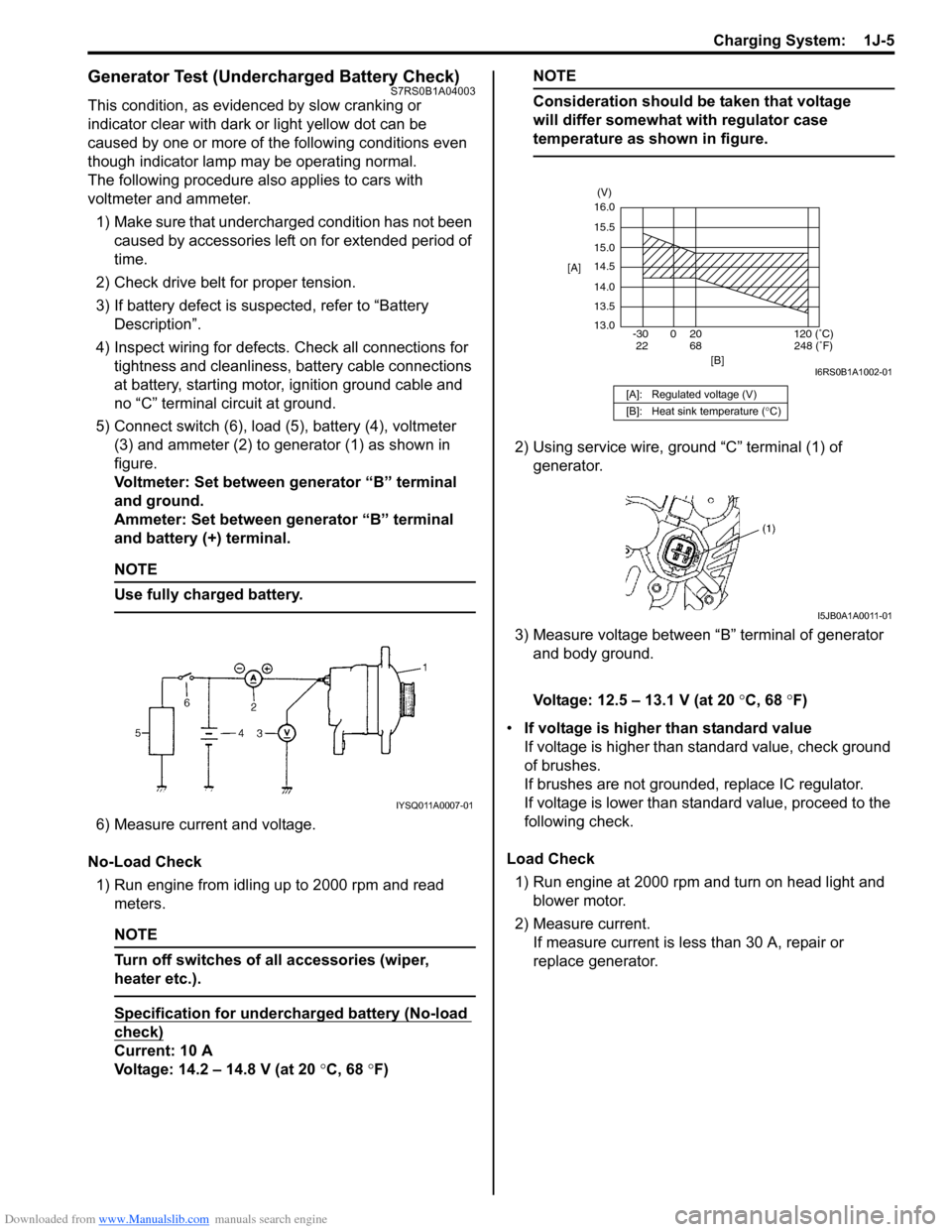
5) Connect switch (6), load (5), battery (4), voltmeter (3) and ammeter (2) to generator (1) as shown in
figure.
Voltmeter: Set between generator “B” terminal
and ground.
Ammeter: Set between generator “B” terminal
and battery (+) terminal.
NOTE
Use fully charged battery.
6) Measure current and voltage.
No-Load Check 1) Run engine from idling up to 2000 rpm and read meters.
NOTE
Turn off switches of all accessories (wiper,
heater etc.).
Specification for undercharged battery (No-load
check)
Current: 10 A
Voltage: 14.2 – 14.8 V (at 20 °C, 68 °F)
NOTE
Consideration should be taken that voltage
will differ somewhat with regulator case
temperature as shown in figure.
2) Using service wire, ground “C” terminal (1) of
generator.
3) Measure voltage between “B” terminal of generator and body ground.
Voltage: 12.5 – 13.1 V (at 20 °C, 68 °F)
• If voltage is higher than standard value
If voltage is higher than standard value, check ground
of brushes.
If brushes are not grounded, replace IC regulator.
If voltage is lower than standard value, proceed to the
following check.
Load Check 1) Run engine at 2000 rpm and turn on head light and blower motor.
2) Measure current. If measure current is less than 30 A, repair or
replace generator.
IYSQ011A0007-01
[A]: Regulated voltage (V)
[B]: Heat sink temperature ( °C)
16.0
15.5
15.0
14.5
14.0
13.5
13.0
-30 0 20
[A]
[B]
68
22120 (˚C)
248 (˚F)
(V)
I6RS0B1A1002-01
I5JB0A1A0011-01
Page 550 of 1496
Downloaded from www.Manualslib.com manuals search engine 4E-11 ABS:
DTC CheckS7RS0B4504004
1) Turn ignition switch to OFF position.
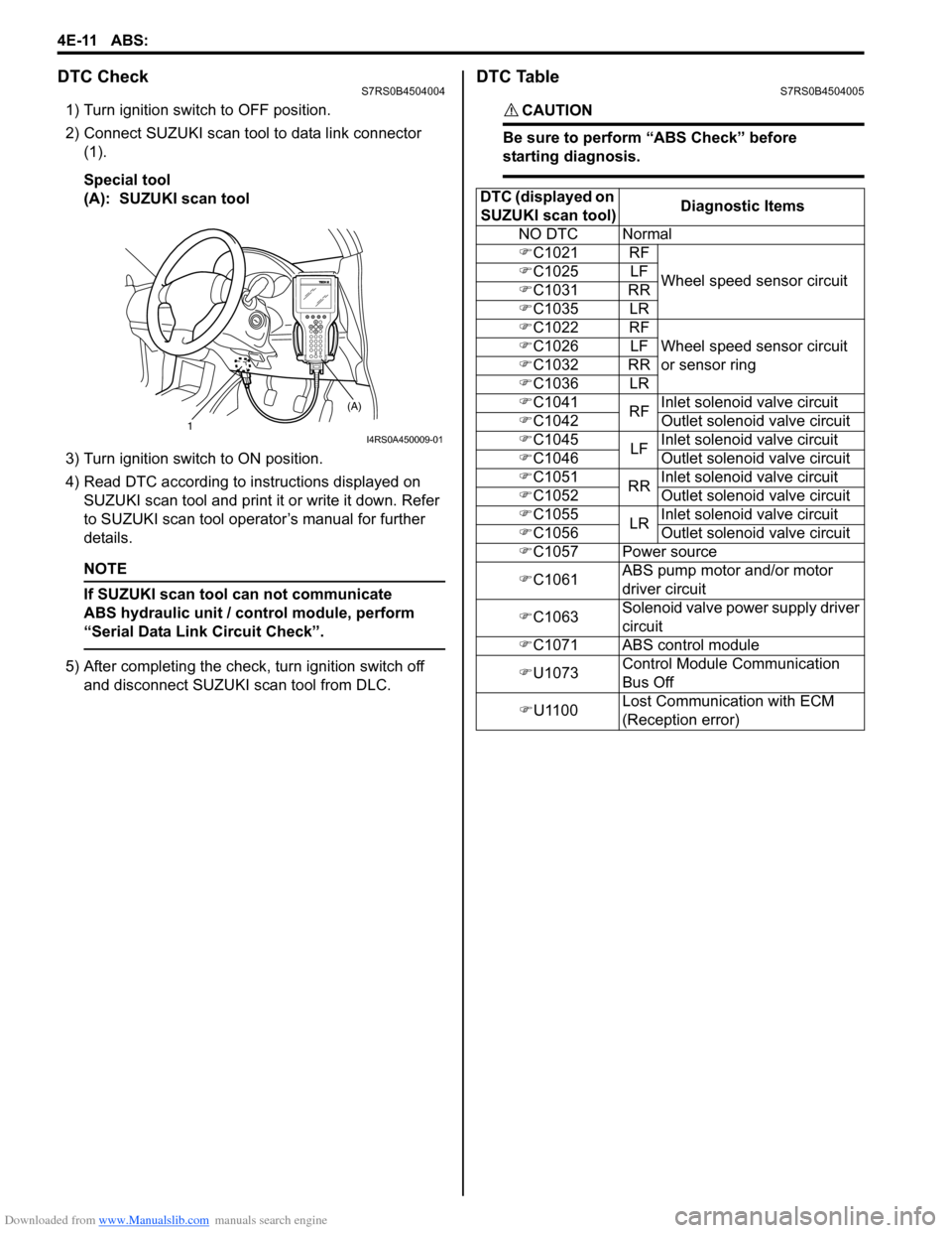
2) Connect SUZUKI scan tool to data link connector (1).
Special tool
(A): SUZUKI scan tool
3) Turn ignition switch to ON position.
4) Read DTC according to instructions displayed on SUZUKI scan tool and print it or write it down. Refer
to SUZUKI scan tool operator’s manual for further
details.
NOTE
If SUZUKI scan tool can not communicate
ABS hydraulic unit / control module, perform
“Serial Data Link Circuit Check”.
5) After completing the check, turn ignition switch off and disconnect SUZUKI scan tool from DLC.
DTC TableS7RS0B4504005
CAUTION!
Be sure to perform “ABS Check” before
starting diagnosis.
1 (A)I4RS0A450009-01
DTC (displayed on
SUZUKI scan tool) Diagnostic Items
NO DTC Normal
�) C1021 RF
Wheel speed sensor circuit
�)
C1025 LF
�) C1031 RR
�) C1035 LR
�) C1022 RF
Wheel speed sensor circuit
or sensor ring
�)
C1026 LF
�) C1032 RR
�) C1036 LR
�) C1041
RFInlet solenoid valve circuit
�) C1042 Outlet solenoid valve circuit
�) C1045
LFInlet solenoid valve circuit
�) C1046 Outlet solenoid valve circuit
�) C1051
RRInlet solenoid valve circuit
�) C1052 Outlet solenoid valve circuit
�) C1055
LRInlet solenoid valve circuit
�) C1056 Outlet solenoid valve circuit
�) C1057 Power source
�) C1061 ABS pump motor and/or motor
driver circuit
�) C1063 Solenoid valve power supply driver
circuit
�) C1071 ABS control module
�) U1073 Control Module
Communication
Bus Off
�) U1100 Lost Communication with ECM
(Reception error)
Page 750 of 1496
Downloaded from www.Manualslib.com manuals search engine 5A-106 Automatic Transmission/Transaxle:
Automatic Transaxle Unit Dismounting and
Remounting
S7RS0B5106031
Dismounting1) Take down transaxle with engine. For its procedure, refer to “Engine Assembly Removal and Installation
in Section 1D”.
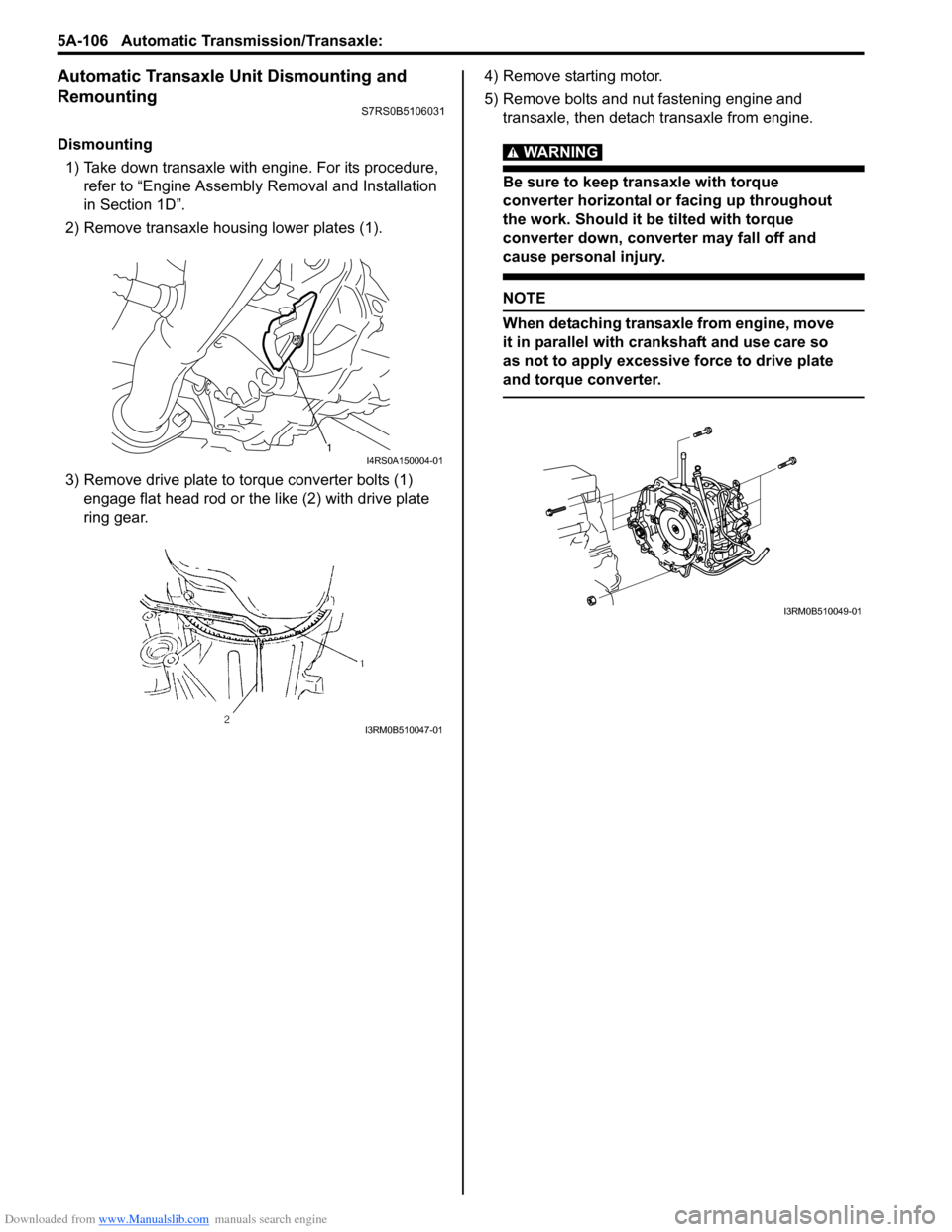
2) Remove transaxle housing lower plates (1).
3) Remove drive plate to torque converter bolts (1) engage flat head rod or the like (2) with drive plate
ring gear. 4) Remove starting motor.
5) Remove bolts and nut fastening engine and
transaxle, then detach transaxle from engine.WARNING!
Be sure to keep transaxle with torque
converter horizontal or facing up throughout
the work. Should it be tilted with torque
converter down, converter may fall off and
cause personal injury.
NOTE
When detaching transaxle from engine, move
it in parallel with cranks haft and use care so
as not to apply excessive force to drive plate
and torque converter.
1I4RS0A150004-01
I3RM0B510047-01
I3RM0B510049-01
Page 823 of 1496
Downloaded from www.Manualslib.com manuals search engine Manual Transmission/Transaxle: 5B-9
Manual Transaxle Unit Dismounting and
Remounting
S7RS0B5206009
Dismounting1) Drain coolant and transaxle oil.
2) Remove coolant reservoir with reservoir hose.
3) Remove battery and tray.
4) Remove air cleaner case and resonator.
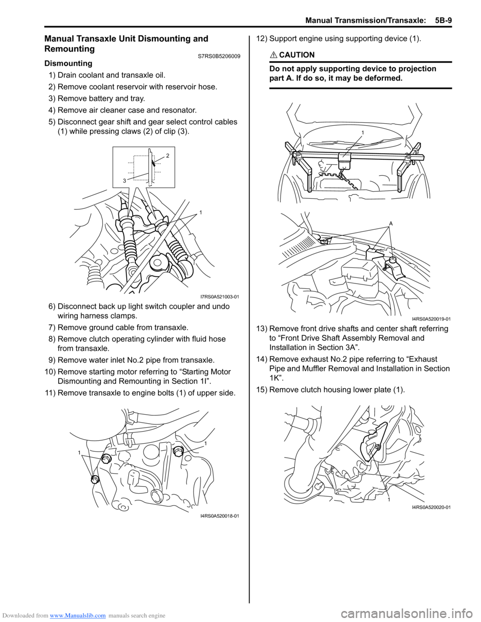
5) Disconnect gear shift and gear select control cables (1) while pressing claws (2) of clip (3).
6) Disconnect back up light switch coupler and undo wiring harness clamps.
7) Remove ground cable from transaxle.
8) Remove clutch operating cylinder with fluid hose from transaxle.
9) Remove water inlet No.2 pipe from transaxle.
10) Remove starting motor re ferring to “Starting Motor
Dismounting and Remounting in Section 1I”.
11) Remove transaxle to engine bolts (1) of upper side. 12) Support engine using supporting device (1).
CAUTION!
Do not apply supporting device to projection
part A. If do so, it may be deformed.
13) Remove front drive shafts and center shaft referring
to “Front Drive Shaft Assembly Removal and
Installation in Section 3A”.
14) Remove exhaust No.2 pipe referring to “Exhaust Pipe and Muffler Removal a nd Installation in Section
1K”.
15) Remove clutch housing lower plate (1).
1
2
3
I7RS0A521003-01
1
1
I4RS0A520018-01
1
A
I4RS0A520019-01
1I4RS0A520020-01
Page 895 of 1496
Downloaded from www.Manualslib.com manuals search engine Power Assisted Steering System: 6C-13
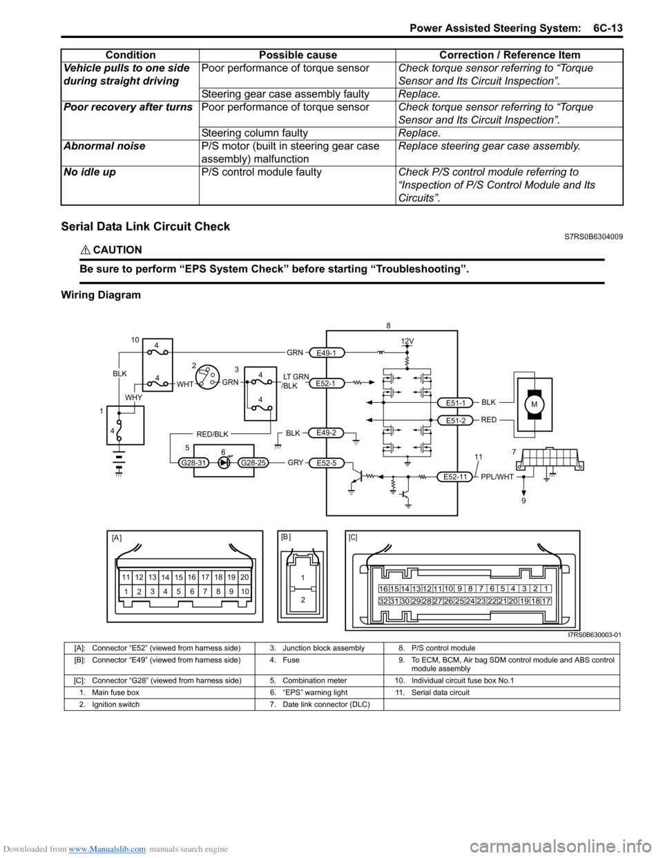
Serial Data Link Circuit CheckS7RS0B6304009
CAUTION!
Be sure to perform “EPS System Check” before starting “Troubleshooting”.
Wiring DiagramVehicle pulls to one side
during straight driving
Poor performance of torque sensor
Check torque sensor referring to “Torque
Sensor and Its Circuit Inspection”.
Steering gear case assembly faulty Replace.
Poor recovery after turns Poor performance of torque sensor Check torque sensor referring to “Torque
Sensor and Its Circuit Inspection”.
Steering column faulty Replace.
Abnormal noise P/S motor (built in steering gear case
assembly) malfunction Replace steering gear case assembly.
No idle up P/S control module faulty Check P/S control module referring to
“Inspection of P/S Control Module and Its
Circuits”.
Condition Possible cause Correction / Reference Item
MBLK
RED
E52-11 E51-1
E51-2PPL/WHT
[A ]
12
3
4 5 67
89
11
10
12 13
141516
17 18 19 2010 9 8 7654 3 21
16 15 14 13 12 11
26 25 24 2322 21 20 19 18 17
32 31 30 29 28 27
[C]
8
79
12V
[B ]
11
12
GRY
LT GRN
/BLK
E52-1
E52-5
E49-1
GRNGRNWHTBLK
WHY
G28-25G28-31
RED/BLK
10
3
4
4
5 6
4
4
1 2
4
E49-2BLK
I7RS0B630003-01
[A]: Connector “E52” (viewed from harness side) 3. Junction block assembly 8. P/S control module
[B]: Connector “E49” (viewed from harness side) 4. Fuse 9. T o ECM, BCM, Air bag SDM control module and ABS control
module assembly
[C]: Connector “G28” (viewed from harness side) 5. Comb ination meter 10. Individual circuit fuse box No.1
1. Main fuse box 6. “EPS” warning light 11. Serial data circuit
2. Ignition switch 7. Date link connector (DLC)
Page 1182 of 1496

Downloaded from www.Manualslib.com manuals search engine 9A-11 Wiring Systems:
C: Engine harnessNo./Color Connective position No./Color Connective positionC01/GRY IAC valve C22/- Generator #2
C02/GRY IG Coil #1 C23/BLK Starting motor #1
C03/GRY IG Coil #2 C24/- Starting motor #2
C04/GRY Fuel injector #1 C25/GR Y VSS (Vehicle speed sensor)
C05/GRY Fuel injector #2 C26/GRY Knock sensor
C06/GRY Fuel injector #3 C27/BLU (A/
T) Input shaft speed sensor
C07/GRY Fuel injector #4 C28/GRY
(A/T) Trans axle range sensor
C08/BLK or GRY CMP sensor C29/GRY
(A/T) Shift solenoid
C09/BLK ECT sensor C30/BLK
(M/T) Back-up light switch
C10/GRY EGR stepper motor C31/- Main fuse box C11/BLK Throttle position sensor C32/GRY
(IF EQPD) Current sensor
C12/BLK MAP sensor C33/- Main fuse box
C13/BLK MAF sensor C34/N (A/T) TCM
C14/BLK EVAP canister purge valve C35/N (A/T) TCM
C15/GRY Heated oxygen sensor #1 C36/N Main harness (To E24)
C16/GRN Heated oxygen sensor #2 C37/GRY ECM C17/BLK A/C compressor C38/- Weld splice C18/N Oil pressure switch C39/- Weld splice
C19/BLU VVT solenoid C40/- Weld splice
C20/GRY CKP sensor C41/- Weld splice
C21/GRY or BLK Generator #1
Page 1184 of 1496

Downloaded from www.Manualslib.com manuals search engine 9A-13 Wiring Systems:
C: Engine harness
D: Oil pressure switch wireNo./Color Connective position No./Color Connective position
C02/GRY IG Coil #1 C24/- Starting motor #2
C03/GRY IG Coil #2 C23/BLK Starting motor #1
C04/GRY Fuel injector #1 C25/GRY
(A/T) VSS (Vehicle speed sensor)
C05/GRY Fuel injector #2 C26/GRY Knock shaft speed sensor
C06/GRY Fuel injector #3 C27/BLU (A/
T) Input shaft speed sensor
C07/GRY Fuel injector #4 C28/GRY
(A/T) Trans axle range sensor
C08/BLK CMP sensor C29/GRY
(A/T) Shift solenoid
C09/BLK ECT sensor C30/BLK
(M/T) Back-up light switch
C10/GRY EGR stepper motor C31/- Main fuse box C12/BLK MAP sensor C32/GRY Current sensor
C13/BLK MAF sensor C33/- Main fuse box
C14/BLK EVAP canister purge valve C34/N (A/T) TCM
C15/BLK Heated oxygen sensor #1 C35/N (A/T) TCM
C16/GRN Heated oxygen sensor #2 C36/N Main harness (To E24) C17/BLK A/C compressor C37/GRY ECM C18/N Oil pressure switch wire (To D02) C38/- Weld splice
C19/BLU VVT solenoid C39/- Weld splice
C20/GRY CKP sensor C40/- Weld splice C21/BLK Generator #1 C42/BLK Electric throttle body C22/- Generator #2
No./Color Connective position No./ColorConnective position
D01/N Oil pressure switch D02/GRY Engine harness (To C18)
Page 1185 of 1496

Downloaded from www.Manualslib.com manuals search engine Wiring Systems: 9A-14
E: Main harness (RHD)
E: Main harness
56
E06E12
E03or
E85
E07
E09
E08
E13
E10
E11E05 E04
E01 E02
E19
7
22
E34E31
E32
E57
E24
(TO C36)
E33
E36
E35
E30
E29
E28
E20
E21
E22
E27
E26
E23
E25E17E56
E18
E14 E15
E55
E
I7RS0B910902-02
No./Color
Connective position No./ColorConnective position
E01/GRY Windshield wiper motor E22/N Front position light (L)
E02/GRY Brake fluid level switch E23/GRY ECM
E03/BLK ABS control module E24/N Engine Harness (To C36)
E04/BLK A/C pressure sensor E25/BLK Wheel speed sensor (FL)
E05/BLK Wheel speed sensor (FR) E26/N Main fuse box
E06/N Side turn signal light (R) E27/BLK Main fuse box
E07/N Front position light (R) E28/BLK Radiator fan relay #1
E08/BLK Head light (R) E29/BLK Radiator fan relay #2
E09/GRY Front turn signal light (R) E30/BLK Radiator fan relay #3
E10/GRN Rear washer motor E31/BLK Starting motor relay
E11/BLU Windshield washer motor E32/BLK Main relay
E12/BLK (IF EQPD) Front fog light (R)
E33/BLK A/T relay
E13/YEL Forward sensor E34/BLK (IF
EQPD) Front fog light relay
E14/BLK Outside air temperature sensor E35/BLK Fuel pump relay
E15/BLK Horn E36/BLK A/C compressor relay
E17/BLK Radiator fan motor E55/- Weld splice
E18/BLK (IF EQPD) Front fog light (L) E56/BLK
(M16A
engine) Throttle actuator control relay
E19/N Side turn signal light (L) E57/BLK Diagnosis connector #1
E20/GRY Front turn signal light (L) E85/BLK (IF
EQPD) ESP
® control module
E21/BLK Headlight (R)
Page 1186 of 1496
Downloaded from www.Manualslib.com manuals search engine 9A-15 Wiring Systems:
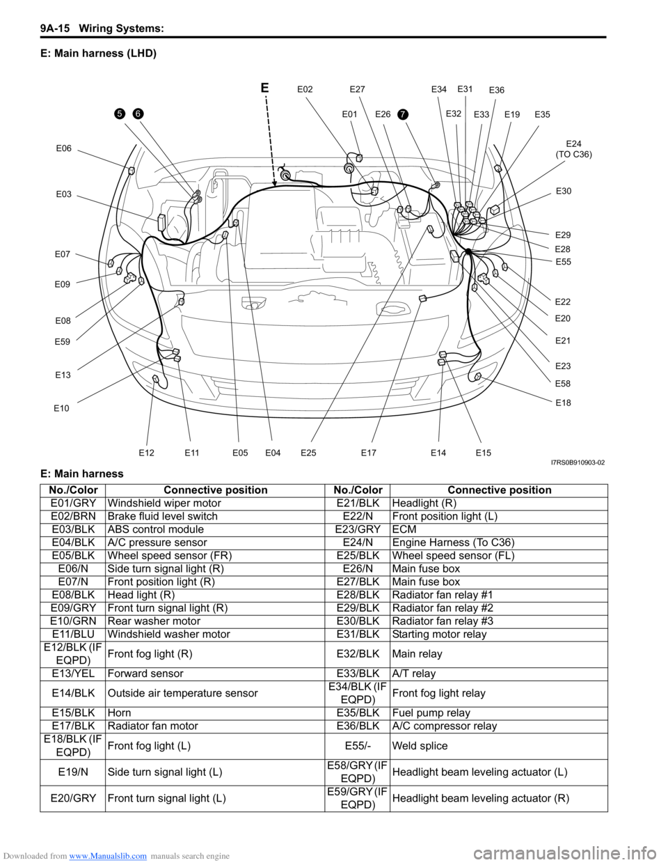
E: Main harness (LHD)
E: Main harness
56
E06E12
E
E03
E07
E09
E59E08
E13
E10
E11E05 E04
E01
E02E197
E34
E31
E32
E24
(TO C36)
E33
E36
E35
E30
E29
E28
E20
E21
E22
E58
E27
E26
E23
E25E17
E18
E14 E15
E55
I7RS0B910903-02
No./Color
Connective position No./ColorConnective position
E01/GRY Windshield wiper motor E21/BLK Headlight (R)
E02/BRN Brake fluid level switch E22/N Front position light (L)
E03/BLK ABS control module E23/GRY ECM
E04/BLK A/C pressure sensor E24/N Engine Harness (To C36)
E05/BLK Wheel speed sensor (FR) E25/BLK Wheel speed sensor (FL)
E06/N Side turn signal light (R) E26/N Main fuse box
E07/N Front position light (R) E27/BLK Main fuse box
E08/BLK Head light (R) E28/BLK Radiator fan relay #1
E09/GRY Front turn signal light (R) E29/BLK Radiator fan relay #2
E10/GRN Rear washer motor E30/BLK Radiator fan relay #3
E11/BLU Windshield washer motor E31/BLK Starting motor relay
E12/BLK (IF EQPD) Front fog light (R)
E32/BLK Main relay
E13/YEL Forward sensor E33/BLK A/T relay
E14/BLK Outside air temperature sensor E34/BLK (IF
EQPD) Front fog light relay
E15/BLK Horn E35/BLK Fuel pump relay
E17/BLK Radiator fan motor E36/BLK A/C compressor relay
E18/BLK (IF
EQPD) Front fog light (L)
E55/- Weld splice
E19/N Side turn signal light (L) E58/GRY (IF
EQPD) Headlight beam leveling actuator (L)
E20/GRY Front turn signal light (L) E59/GRY (IF
EQPD) Headlight beam leveling actuator (R)
Page 1203 of 1496
Downloaded from www.Manualslib.com manuals search engine Wiring Systems: 9A-32
G32
J/B
3
WHT/BLU
4G213
12
10
BLK
21
BLK/GRY
10A
15A30A
5647891012
E27
WHT
131416192021
BLUBLU/YEL
6
BLK/YEL
5
YEL/BLU
7
PNK
89
WHT/RED
RED
GRN
12
WHT
GRY
14
WHT/GRN
19
WHT/BLU
2021
WHT/REDWHT/BLU
16
15A
15A 30A 50A
30A
30A 30A
30A
15A15A
15A
BLK
2E261
WHT/BLU
C31 C331 1
WHT
BLK
Main fuse box
Starting motor "A-1"
Generator
"A-2"
Battery
80A
50A
50A
3
80A
47
80A
46
2
1
E401WHT
"Junction Block
Inner circuit"
J/B (E40- )
YEL
"Junction BlockInner circuit"
J/B (G32- )
2
1
"Junction BlockInner circuit"
J/B (E39- ) 7
J/B (G32- ) 4
GRN/WHT
Individual circuit fuse box
+B1
LOCK
ACC
ON
ST ACC IG1 IG2
STOUT
IN
+B2
6
GRN
J/B (G32- )
2
5BLU
J/B (G32- )5
IF EQPD
18
YEL/BLU
18
15A
M16A engine
W
B
RHD
LHDAB
A
A
B1 2AB21
B
I6RS0C910907-01