Body SUZUKI SWIFT 2006 2.G Service Workshop Manual
[x] Cancel search | Manufacturer: SUZUKI, Model Year: 2006, Model line: SWIFT, Model: SUZUKI SWIFT 2006 2.GPages: 1496, PDF Size: 34.44 MB
Page 913 of 1496
Downloaded from www.Manualslib.com manuals search engine Power Assisted Steering System: 6C-31
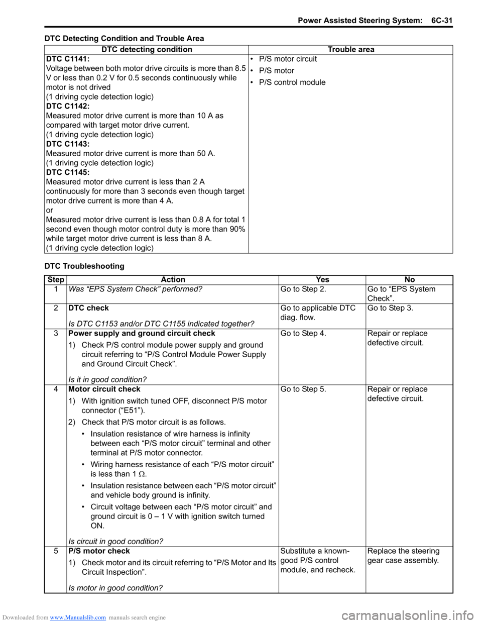
DTC Detecting Condition and Trouble Area
DTC TroubleshootingDTC detecting condition Trouble area
DTC C1141:
Voltage between both motor drive circuits is more than 8.5
V or less than 0.2 V for 0.5 seconds continuously while
motor is not drived
(1 driving cycle detection logic)
DTC C1142:
Measured motor drive current is more than 10 A as
compared with target motor drive current.
(1 driving cycle detection logic)
DTC C1143:
Measured motor drive current is more than 50 A.
(1 driving cycle detection logic)
DTC C1145:
Measured motor drive current is less than 2 A
continuously for more than 3 seconds even though target
motor drive current is more than 4 A.
or
Measured motor drive current is less than 0.8 A for total 1
second even though motor cont rol duty is more than 90%
while target motor drive current is less than 8 A.
(1 driving cycle detection logic) • P/S motor circuit
• P/S motor
• P/S control module
Step
Action YesNo
1 Was “EPS System Check” performed? Go to Step 2.Go to “EPS System
Check”.
2 DTC check
Is DTC C1153 and/or DTC C1155 indicated together? Go to applicable DTC
diag. flow.
Go to Step 3.
3 Power supply and ground circuit check
1) Check P/S control module power supply and ground
circuit referring to “P/S Control Module Power Supply
and Ground Circuit Check”.
Is it in good condition? Go to Step 4.
Repair or replace
defective circuit.
4 Motor circuit check
1) With ignition switch tuned OFF, disconnect P/S motor
connector (“E51”).
2) Check that P/S motor circuit is as follows. • Insulation resistance of wire harness is infinity between each “P/S motor circuit” terminal and other
terminal at P/S motor connector.
• Wiring harness resistance of each “P/S motor circuit”
is less than 1 Ω.
• Insulation resistance between each “P/S motor circuit” and vehicle body ground is infinity.
• Circuit voltage between each “P/S motor circuit” and ground circuit is 0 – 1 V with ignition switch turned
ON.
Is circuit in good condition? Go to Step 5.
Repair or replace
defective circuit.
5 P/S motor check
1) Check motor and its circuit referring to “P/S Motor and Its
Circuit Inspection”.
Is motor in good condition? Substitute a known-
good P/S control
module, and recheck.
Replace the steering
gear case assembly.
Page 914 of 1496
Downloaded from www.Manualslib.com manuals search engine 6C-32 Power Assisted Steering System:
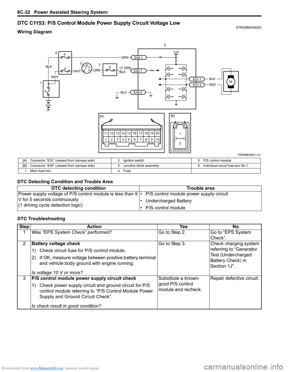
DTC C1153: P/S Control Module Power Supply Circuit Voltage LowS7RS0B6304020
Wiring Diagram
DTC Detecting Condition and Trouble Area
DTC Troubleshooting
MBLK
REDE51-1
E51-2
12V
5
[A ]
12 3
4 5 67
89
11
10
12 13
141516
17 18 19 20
[B ]
1
2
LT GRN
/BLKE52-1 E49-1
GRNGRNWHTBLK
WHY
6
3
4
4
4
4
1 2
E49-2BLK
I7RS0B630011-01
[A]: Connector “E52” (viewed from harness side)
2. Ignition switch5. P/S control module
[B]: Connector “E49” (viewed from harness side) 3. Junction block assembly 6. Individual circuit fuse box No.1
1. Main fuse box 4. Fuse
DTC detecting condition Trouble area
Power supply voltage of P/S control module is less than 9
V for 5 seconds continuously
(1 driving cycle detection logic) • P/S control module power supply circuit
• Undercharged Battery
• P/S control module
Step
Action YesNo
1 Was “EPS System Check” performed? Go to Step 2.Go to “EPS System
Check”.
2 Battery voltage check
1) Check circuit fuse for P/S control module.
2) If OK, measure voltage between positive battery terminal
and vehicle body ground with engine running.
Is voltage 10 V or more? Go to Step 3.
Check charging system
referring to “Generator
Test (Undercharged
Battery Check) in
Section 1J”.
3 P/S control module power supply circuit check
1) Check power supply circuit and ground circuit for P/S
control module referring to “P/S Control Module Power
Supply and Ground Circuit Check”.
Is check result in good condition? Substitute a known-
good P/S control
module and recheck.
Repair defective circuit.
Page 915 of 1496
Downloaded from www.Manualslib.com manuals search engine Power Assisted Steering System: 6C-33
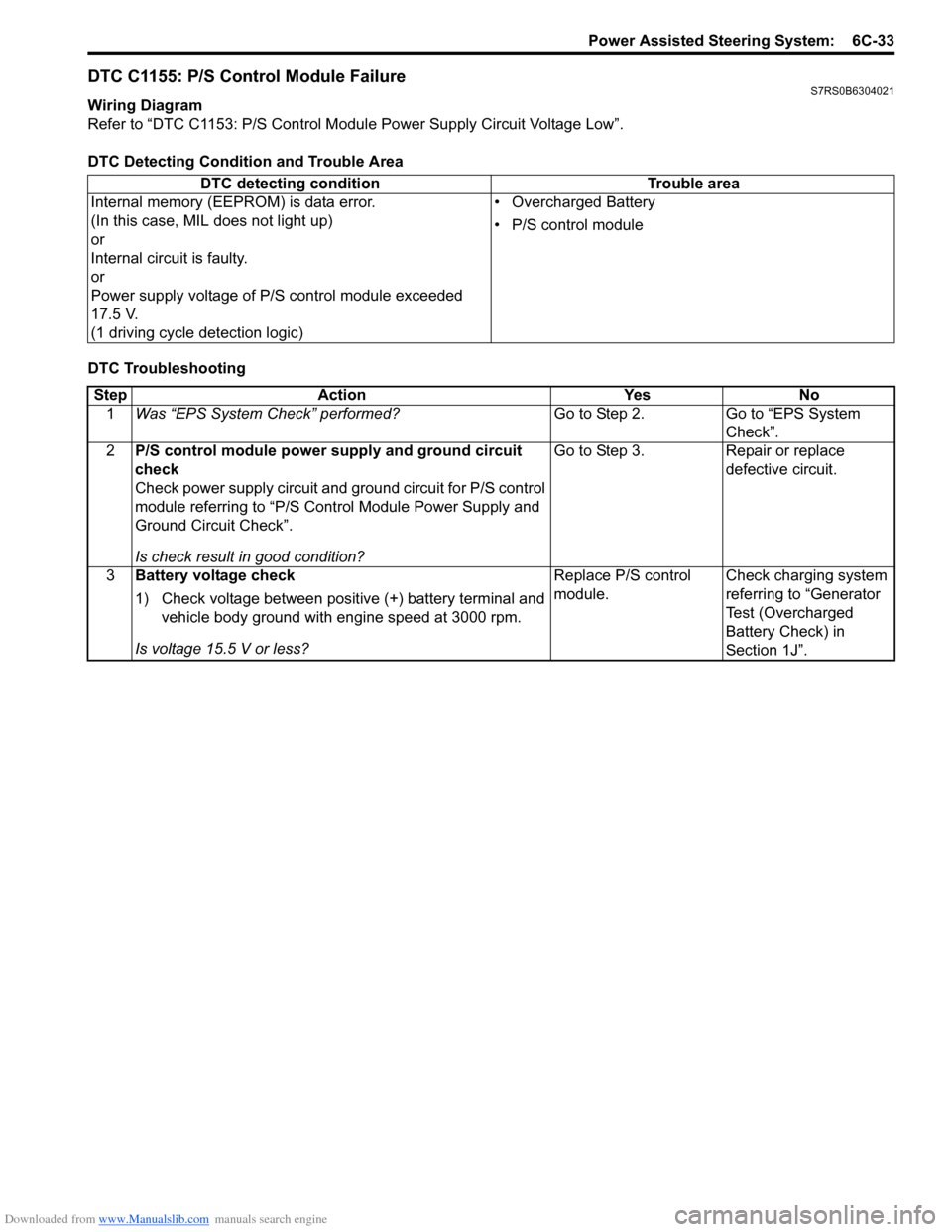
DTC C1155: P/S Control Module FailureS7RS0B6304021
Wiring Diagram
Refer to “DTC C1153: P/S Control Module Power Supply Circuit Voltage Low”.
DTC Detecting Condition and Trouble Area
DTC Troubleshooting DTC detecting condition Trouble area
Internal memory (EEPROM) is data error.
(In this case, MIL does not light up)
or
Internal circuit is faulty.
or
Power supply voltage of P/S control module exceeded
17.5 V.
(1 driving cycle detection logic) • Overcharged Battery
• P/S control module
Step
Action YesNo
1 Was “EPS System Check” performed? Go to Step 2.Go to “EPS System
Check”.
2 P/S control module power supply and ground circuit
check
Check power supply circuit and ground circuit for P/S control
module referring to “P/S Control Module Power Supply and
Ground Circuit Check”.
Is check result in good condition? Go to Step 3.
Repair or replace
defective circuit.
3 Battery voltage check
1) Check voltage between positive (+) battery terminal and
vehicle body ground with engine speed at 3000 rpm.
Is voltage 15.5 V or less? Replace P/S control
module.
Check charging system
referring to “Generator
Test (Overcharged
Battery Check) in
Section 1J”.
Page 916 of 1496
![SUZUKI SWIFT 2006 2.G Service Workshop Manual Downloaded from www.Manualslib.com manuals search engine 6C-34 Power Assisted Steering System:
P/S Control Module Power Supply and Ground Circuit CheckS7RS0B6304022
Wiring Diagram
1
[A ]
123
4 5 67
8 SUZUKI SWIFT 2006 2.G Service Workshop Manual Downloaded from www.Manualslib.com manuals search engine 6C-34 Power Assisted Steering System:
P/S Control Module Power Supply and Ground Circuit CheckS7RS0B6304022
Wiring Diagram
1
[A ]
123
4 5 67
8](/img/20/7607/w960_7607-915.png)
Downloaded from www.Manualslib.com manuals search engine 6C-34 Power Assisted Steering System:
P/S Control Module Power Supply and Ground Circuit CheckS7RS0B6304022
Wiring Diagram
1
[A ]
123
4 5 67
89
11
10
12 13
141516
17 18 19 20
[B ]
7
1
2
MBLK
REDE51-1
E51-2
12V
LT GRN
/BLKE52-1 E49-1
GRNGRNWHTBLK
WHY
3
3
5
6
1 2
E49-2BLK
I7RS0B630012-01
[A]: Connector “E52” (viewed from harness side)
2. Ignition switch5. “EPS” fuse
[B]: Connector “E49” (viewed from harness side) 3. Individual circuit fuse box No.1 6. “IG1 SIG” fuse
1. Main fuse box 4. Junction block assembly7. P/S control module
StepAction YesNo
1 Circuit fuse check
1) Disconnect P/S control modu le connector with ignition
switch turned OFF.
2) Check for proper connection to P/S control module connector at “E49-1”, “E49-2” and “E52-1” terminals.
3) If OK, check “P/S” fuse and “IG1 SIG” fuse for blowing.
Are “P/S” fuse and “IG1 SIG” fuse in good condition? Go to Step 2.
Replace fuse(s) and
check for short in
circuits connected to
fuse(s).
2 Power supply circuit check
1) Measure voltage between “E49-1” terminal of P/S
control module connector and body ground.
Is voltage 10 - 14 V? Go to Step 3.
“GRN” or “BLK” wire is
open circuit.
3 Ignition signal check
1) Turn ignition switch to ON position.
2) Measure voltage between “E52-1” terminal of P/S
control module connector and body ground.
Is voltage 10 - 14 V? Go to Step 4.
“LT GRN/BLK” or “GRN”
wire is open circuit.
4 P/S control module ground circuit check
1) Turn ignition switch to OFF position.
2) Disconnect connectors from P/S control module.
3) Measure resistance between “E49-2” terminals of P/S
control module connector and body ground.
Is resistance 1
Ω or less? Go to Step 5. “BLK” wire is open or
high resistance circuit.
Page 917 of 1496
Downloaded from www.Manualslib.com manuals search engine Power Assisted Steering System: 6C-35
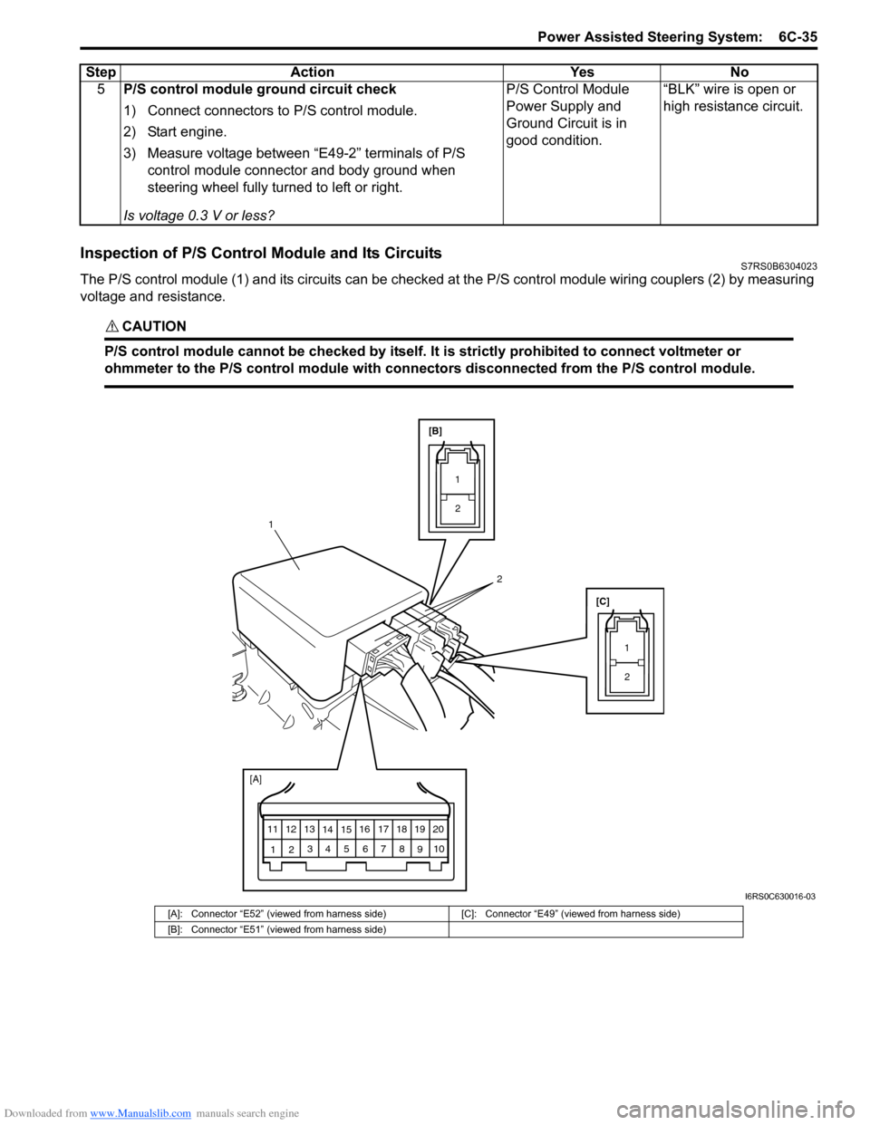
Inspection of P/S Control Module and Its CircuitsS7RS0B6304023
The P/S control module (1) and its circuits can be checked at the P/S control module wiring couplers (2) by measuring
voltage and resistance.
CAUTION!
P/S control module cannot be checked by itself. It is strictly prohibited to connect voltmeter or
ohmmeter to the P/S control module with connectors disconnected from the P/S control module.
5 P/S control module ground circuit check
1) Connect connectors to P/S control module.
2) Start engine.
3) Measure voltage between “E49-2” terminals of P/S
control module connector and body ground when
steering wheel fully turned to left or right.
Is voltage 0.3 V or less? P/S Control Module
Power Supply and
Ground Circuit is in
good condition.
“BLK” wire is open or
high resistance circuit.
Step Action Yes No
[A]
12
3
4 5 67
89
11
10
12 13
141516
17 18 19 20
[B]
[C]
12
1
1 2
2
I6RS0C630016-03
[A]: Connector “E52” (viewed from harness side) [C]: Connector “E49” (viewed from harness side)
[B]: Connector “E51” (viewed from harness side)
Page 918 of 1496
Downloaded from www.Manualslib.com manuals search engine 6C-36 Power Assisted Steering System:
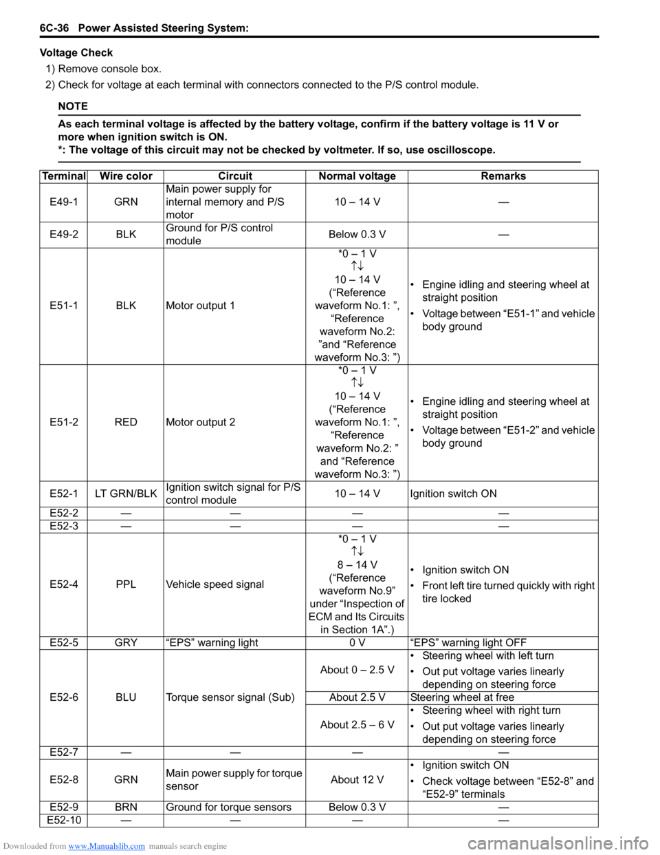
Voltage Check1) Remove console box.
2) Check for voltage at each terminal with co nnectors connected to the P/S control module.
NOTE
As each terminal voltage is affected by the battery voltage, confirm if the battery voltage is 11 V or
more when ignition switch is ON.
*: The voltage of this circuit may not be checked by voltmeter. If so, use oscilloscope.
Terminal Wire colorCircuit Normal voltage Remarks
E49-1 GRN Main power supply for
internal memory and P/S
motor 10 – 14 V
—
E49-2 BLK Ground for P/S control
module Below 0.3 V
—
E51-1 BLK Motor output 1 *0 – 1 V
↑↓
10 – 14 V
(“Reference
waveform No.1: ”, “Reference
waveform No.2:
”and “Reference
waveform No.3: ”) • Engine idling and steering wheel at
straight position
• Voltage between “E51-1” and vehicle body ground
E51-2 RED Motor output 2 *0 – 1 V
↑↓
10 – 14 V
(“Reference
waveform No.1: ”, “Reference
waveform No.2: ” and “Reference
waveform No.3: ”) • Engine idling and steering wheel at
straight position
• Voltage between “E51-2” and vehicle body ground
E52-1 LT GRN/BLK Ignition switch signal for P/S
control module 10 – 14 V Ignition switch ON
E52-2 — —— —
E52-3 — —— —
E52-4 PPL Vehicle speed signal *0 – 1 V
↑↓
8 – 14 V
(“Reference
waveform No.9”
under “Inspection of
ECM and Its Circuits in Section 1A”.) • Ignition switch ON
•Front left tire tu
rned quickly with right
tire locked
E52-5 GRY “EPS” warning light 0 V “EPS” warning light OFF
E52-6 BLU Torque sensor signal (Sub) About 0 – 2.5 V
• Steering wheel with left turn
• Out put voltage varies linearly
depending on steering force
About 2.5 V Steering wheel at free
About 2.5 – 6 V • Steering wheel with right turn
• Out put voltage varies linearly
depending on steering force
E52-7 — —— —
E52-8 GRN Main power supply for torque
sensor About 12 V• Ignition switch ON
• Check voltage between “E52-8” and
“E52-9” terminals
E52-9 BRN Ground for torque sensors Below 0.3 V —
E52-10 — —— —
Page 920 of 1496
Downloaded from www.Manualslib.com manuals search engine 6C-38 Power Assisted Steering System:
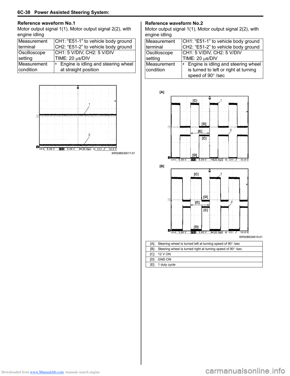
Reference waveform No.1
Motor output signal 1(1), Motor output signal 2(2), with
engine idlingReference waveform No.2
Motor output signal 1(1), Motor output signal 2(2), with
engine idling
Measurement
terminal CH1: “E51-1” to vehicle body ground
CH2: “E51-2” to vehicle body ground
Oscilloscope
setting CH1: 5 V/DIV, CH2: 5 V/DIV
TIME: 20
µs/DIV
Measurement
condition • Engine is idling and steering wheel
at straight position
I6RS0B630017-01
Measurement
terminal CH1: “E51-1” to vehicle body ground
CH2: “E51-2” to vehicle body ground
Oscilloscope
setting CH1: 5 V/DIV, CH2: 5 V/DIV
TIME: 20 µ
s/DIV
Measurement
condition • Engine is idling and steering wheel
is turned to left or right at turning
speed of 90 ° /sec
[A]: Steering wheel is turned left at turning speed of 90 ° /sec
[B]: Steering wheel is turned right at turning speed of 90 ° /sec
[C]: 12 V ON
[D]: GND ON [E]: 1 duty cycle
I6RS0B630018-01
Page 921 of 1496
Downloaded from www.Manualslib.com manuals search engine Power Assisted Steering System: 6C-39
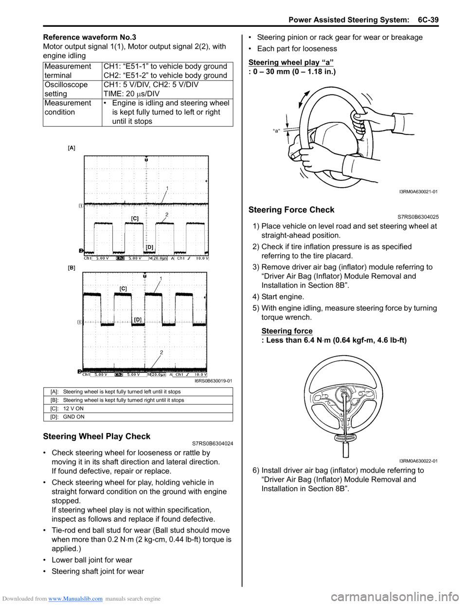
Reference waveform No.3
Motor output signal 1(1), Motor output signal 2(2), with
engine idling
Steering Wheel Play CheckS7RS0B6304024
• Check steering wheel for looseness or rattle by moving it in its shaft direction and lateral direction.
If found defective, repair or replace.
• Check steering wheel for play, holding vehicle in straight forward condition on the ground with engine
stopped.
If steering wheel play is not within specification,
inspect as follows and replace if found defective.
• Tie-rod end ball stud for wear (Ball stud should move when more than 0.2 N ⋅m (2 kg-cm, 0.44 lb-ft) torque is
applied.)
• Lower ball joint for wear
• Steering shaft joint for wear • Steering pinion or rack gear for wear or breakage
• Each part for looseness
Steering wheel play
“a”
: 0 – 30 mm (0 – 1.18 in.)
Steering Force CheckS7RS0B6304025
1) Place vehicle on level road and set steering wheel at
straight-ahead position.
2) Check if tire inflation pressure is as specified referring to the tire placard.
3) Remove driver air bag (inflator) module referring to “Driver Air Bag (Inflator) Module Removal and
Installation in Section 8B”.
4) Start engine.
5) With engine idling, measure steering force by turning torque wrench.
Steering force
: Less than 6.4 N ⋅m (0.64 kgf-m, 4.6 lb-ft)
6) Install driver air bag (inflator) module referring to “Driver Air Bag (Inflator) Module Removal and
Installation in Section 8B”.
Measurement
terminal
CH1: “E51-1” to vehicle body ground
CH2: “E51-2” to vehicle body ground
Oscilloscope
setting CH1: 5 V/DIV, CH2: 5 V/DIV
TIME: 20
µs/DIV
Measurement
condition • Engine is idling and steering wheel
is kept fully turned to left or right
until it stops
[A]: Steering wheel is kept fully turned left until it stops
[B]: Steering wheel is kept fully turned right until it stops
[C]: 12 V ON
[D]: GND ON
I6RS0B630019-01
I3RM0A630021-01
I3RM0A630022-01
Page 929 of 1496
Downloaded from www.Manualslib.com manuals search engine Power Assisted Steering System: 6C-47
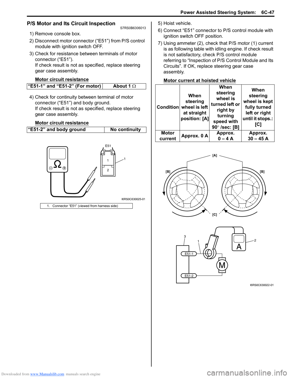
P/S Motor and Its Circuit InspectionS7RS0B6306013
1) Remove console box.
2) Disconnect motor connector (“E51”) from P/S control module with ignition switch OFF.
3) Check for resistance between terminals of motor connector (“E51”).
If check result is not as specified, replace steering
gear case assembly.
Motor circuit resistance
4) Check for continuity between terminal of motor connector (“E51”) and body ground.
If check result is not as specified, replace steering
gear case assembly.
Motor circuit resistance
5) Hoist vehicle.
6) Connect “E51” connector to P/S control module with ignition switch OFF position.
7) Using ammeter (2), check that P/S motor (1) current is as following table with id ling engine. If check result
is not satisfactory, check P/S control module
referring to “Inspection of P/S Control Module and Its
Circuits”. If OK, replace steering gear case
assembly.
Motor current at hoisted vehicle
“E51-1” and “E51-2” (For motor) About 1 Ω
“E51-2” and body ground No continuity
1. Connector “E51” (viewed from harness side)
E51
11 2
I6RS0C630025-01
Condition When
steering
wheel is left at straight
position: [A] When
steering
wheel is
turned left or right by turning
speed with
90° /sec: [B] When
steering
wheel is kept fully turned left or right
until it stops.: [C]
Motor
current Approx. 0 A Approx.
0 – 4 A Approx.
30 – 45 A
1
32
E51-1
E51-2
[C] [A]
[B] [B]
I6RS0C630022-01
Page 940 of 1496
Downloaded from www.Manualslib.com manuals search engine 7A-4 Heater and Ventilation:
Repair Instructions
HVAC Unit ComponentsS7RS0B7106001
For manual type A/C, refer to “HVAC Unit Components
in Section 7B”.
For automatic type A/C, refer to “HVAC Unit
Components in Section 7B”.
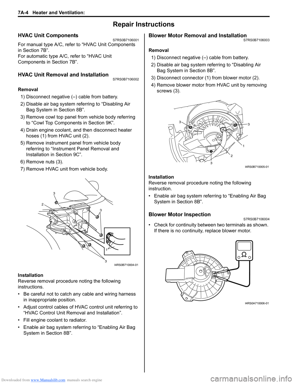
HVAC Unit Removal and InstallationS7RS0B7106002
Removal
1) Disconnect negative (–) cable from battery.
2) Disable air bag system referring to “Disabling Air Bag System in Section 8B”.
3) Remove cowl top panel from vehicle body referring to “Cowl Top Components in Section 9K”.
4) Drain engine coolant, and then disconnect heater hoses (1) from HVAC unit (2).
5) Remove instrument panel from vehicle body referring to “Instrument Panel Removal and
Installation in Section 9C”.
6) Remove nuts (3).
7) Remove HVAC unit from vehicle body.
Installation
Reverse removal procedure noting the following
instructions.
• Be careful not to catch any cable and wiring harness in inappropriate position.
• Adjust control cables of HVAC control unit referring to “HVAC Control Unit Remo val and Installation”.
• Fill engine coolant to radiator.
• Enable air bag system referring to “Enabling Air Bag System in Section 8B”.
Blower Motor Removal and InstallationS7RS0B7106003
Removal
1) Disconnect negative (–) cable from battery.
2) Disable air bag system referring to “Disabling Air Bag System in Section 8B”.
3) Disconnect connector (1) from blower motor (2).
4) Remove blower motor from HVAC unit by removing screws (3).
Installation
Reverse removal procedure noting the following
instruction.
• Enable air bag system referring to “Enabling Air Bag System in Section 8B”.
Blower Motor InspectionS7RS0B7106004
• Check for continuity between two terminals as shown. If there is no continuity, replace blower motor.
3
2
3
1
3I4RS0B710004-01
3
1
2
3
3
I4RS0B710005-01
I4RS0A710006-01