Body SUZUKI SWIFT 2006 2.G Service Workshop Manual
[x] Cancel search | Manufacturer: SUZUKI, Model Year: 2006, Model line: SWIFT, Model: SUZUKI SWIFT 2006 2.GPages: 1496, PDF Size: 34.44 MB
Page 784 of 1496
Downloaded from www.Manualslib.com manuals search engine 5A-140 Automatic Transmission/Transaxle:
Valve Body Assembly Disassembly and
Reassembly
S7RS0B5106053
CAUTION!
When replacing pressure control solenoid
valve and/or TCC pressure control solenoid
valve, it is strictly required to replace it
together with valve body assembly as a set.
Replacing pressure control solenoid valve
and/or TCC pressure control solenoid valve
independently may cause excessive shift
shock.
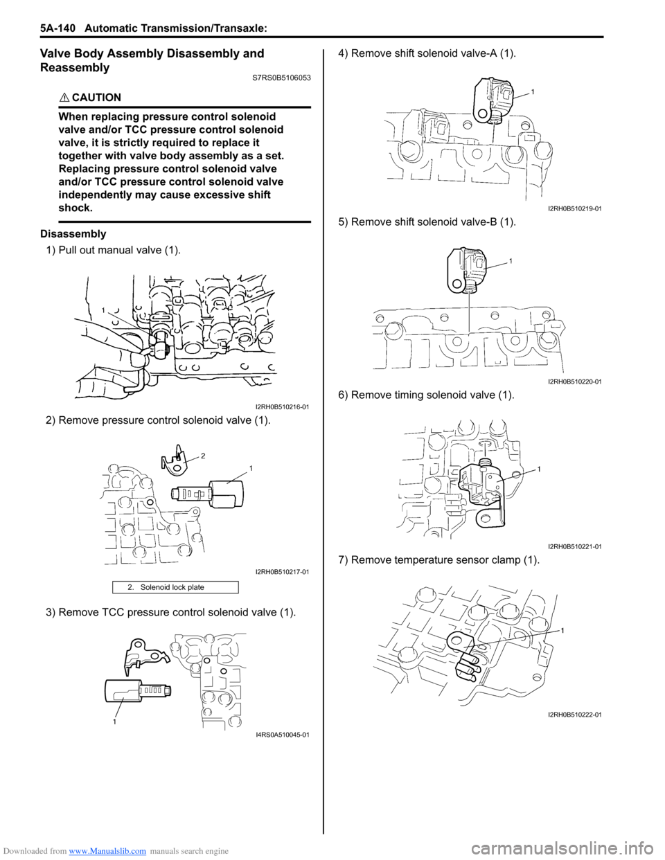
Disassembly1) Pull out manual valve (1).
2) Remove pressure cont rol solenoid valve (1).
3) Remove TCC pressure control solenoid valve (1). 4) Remove shift solenoid valve-A (1).
5) Remove shift solenoid valve-B (1).
6) Remove timing solenoid valve (1).
7) Remove temperature sensor clamp (1).
2. Solenoid lock plate
I2RH0B510216-01
I2RH0B510217-01
1
I4RS0A510045-01
I2RH0B510219-01
I2RH0B510220-01
I2RH0B510221-01
I2RH0B510222-01
Page 785 of 1496
Downloaded from www.Manualslib.com manuals search engine Automatic Transmission/Transaxle: 5A-141
Reassembly
Reverse disassembly procedure for assembly, noting the
following points.
• Shift solenoid valve-A and -B are identical
• After applying A/T fluid to new O-rings, fit them to solenoid valves, then insta ll solenoid valves to valve
body.
• Tighten solenoid valve bolts to specified torque
Tightening torque
Solenoid valve bolt (a): 11 N·m (1.1 kgf-m, 8.0 lb-ft)
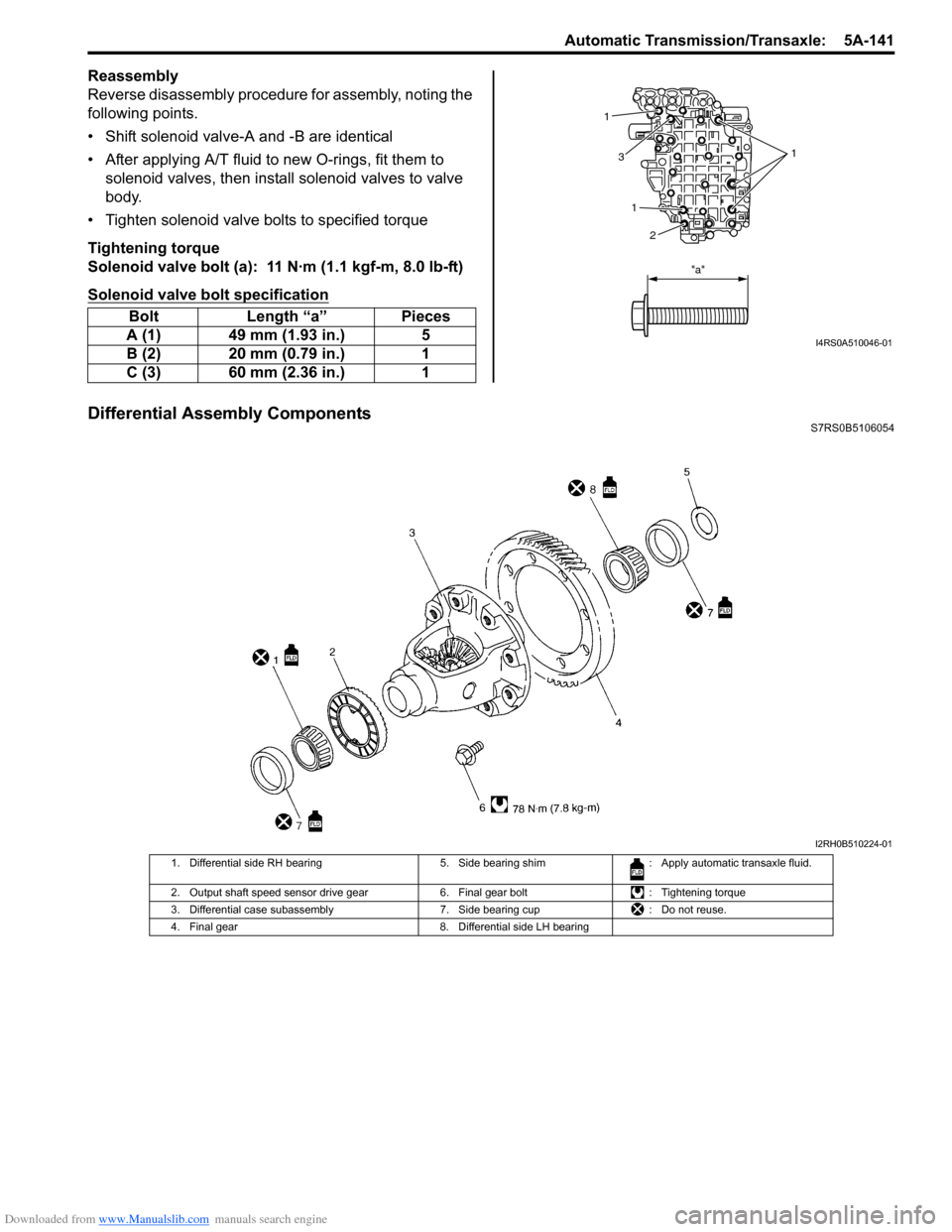
Solenoid valve bolt specification
Differential Assembly ComponentsS7RS0B5106054
Bolt Length “a” Pieces
A (1) 49 mm (1.93 in.) 5
B (2) 20 mm (0.79 in.) 1
C (3) 60 mm (2.36 in.) 1
1
1
1
3
2
"a"
I4RS0A510046-01
I2RH0B510224-01
1. Differential side RH bearing 5. Side bearing shim: Apply automatic transaxle fluid.
2. Output shaft speed sensor drive gear 6. Final gear bolt: Tightening torque
3. Differential case subassembly 7. Side bearing cup: Do not reuse.
4. Final gear 8. Differential side LH bearing
Page 807 of 1496
Downloaded from www.Manualslib.com manuals search engine Automatic Transmission/Transaxle: 5A-163
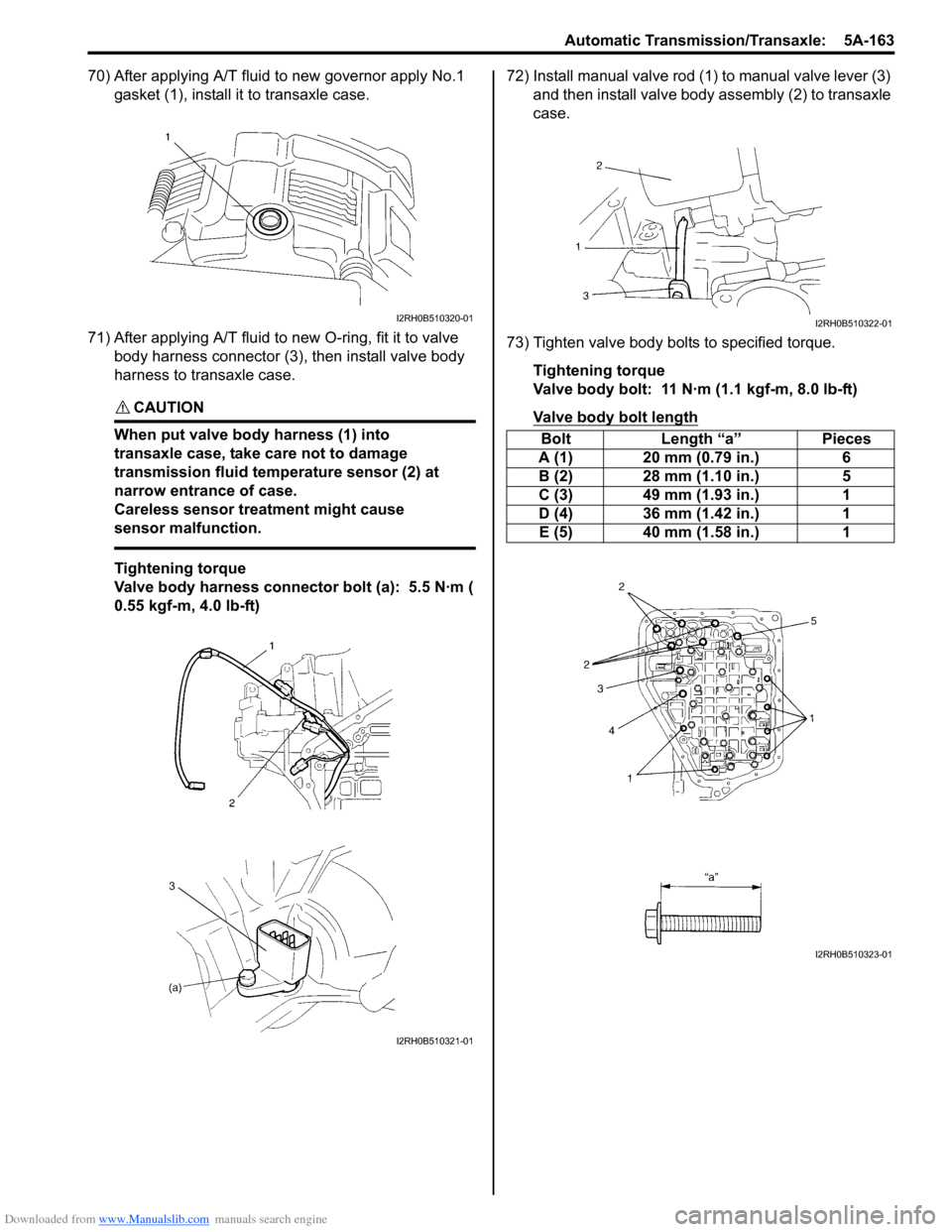
70) After applying A/T fluid to new governor apply No.1 gasket (1), install it to transaxle case.
71) After applying A/T fluid to new O-ring, fit it to valve body harness connector (3), then install valve body
harness to transaxle case.
CAUTION!
When put valve body harness (1) into
transaxle case, take care not to damage
transmission fluid temperature sensor (2) at
narrow entrance of case.
Careless sensor treatment might cause
sensor malfunction.
Tightening torque
Valve body harness connector bolt (a): 5.5 N·m (
0.55 kgf-m, 4.0 lb-ft) 72) Install manual valve rod (1) to manual valve lever (3)
and then install valve body assembly (2) to transaxle
case.
73) Tighten valve body bolts to specified torque. Tightening torque
Valve body bolt: 11 N·m (1.1 kgf-m, 8.0 lb-ft)
Valve body bolt length
I2RH0B510320-01
I2RH0B510321-01
Bolt Length “a” Pieces
A (1) 20 mm (0.79 in.) 6
B (2) 28 mm (1.10 in.) 5
C (3) 49 mm (1.93 in.) 1
D (4) 36 mm (1.42 in.) 1
E (5) 40 mm (1.58 in.) 1
I2RH0B510322-01
I2RH0B510323-01
Page 811 of 1496

Downloaded from www.Manualslib.com manuals search engine Automatic Transmission/Transaxle: 5A-167
Specifications
Tightening Torque SpecificationsS7RS0B5107001
NOTE
The specified tightening torque is also described in the following.
“Select Cable Components”
“Automatic Transaxle Unit Components”
“Automatic Transaxle Assembly Components”
“Oil Pump Assembly Components”
“Transaxle Rear Cover (O/D and 2nd Coast Brake Piston) Assembly Components”
“Valve Body Assembly Components”
“Differential Assembly Components”
Reference:
For the tightening torque of fastener not specified in this section, refer to “Fasteners Information in Section 0A”.
Fastening part
Tightening torque
Note
N ⋅mkgf-mlb-ft
A/T fluid drain plug 171.7 12.5 �) / �) / �)
Transmission range sensor bolt 5.5 0.55 4.0�) / �)
Output shaft speed sensor bolt 131.3 9.5 �) / �)
Input shaft speed sensor bolt 5.5 0.55 4.0�)
Valve body harness connector bolt 7.00.7 5.0 �)
Shift solenoid bolt 111.1 8.0 �)
Oil strainer bolt 101.0 7.5 �) / �)
Oil pan bolt 7.00.7 5.0 �) / �)
Transaxle and engine fastening bolt and nut 85 8.5 61.5�)
Drive plate to torque converter bolt 252.5 18.0 �)
Transaxle stiffener bolt 555.5 40�)
Starter motor bolt and nut 505.0 36.5 �)
Oil pump subassembly bolt 101.0 7.5 �)
Rear cover plug 7.5 0.75 5.5�)
Solenoid valve bolt 111.1 8.0 �)
Final gear bolt 787.8 56.5 �)
Torque converter housing plug 7.5 0.75 5.5�)
Lubrication tube clamp bolt 5.5 0.55 4.0�)
Fluid reservoir RH plate bolt 5.5 0.55 4.0�)
Torque converter housing bolt 292.9 21�) / �) / �)
Manual detent spring bolt 101.0 7.5 �)
Parking lock pawl bracket bolt 7.5 0.75 5.5�)
Rear cover bolt 252.5 18.0 �)
Fluid reservoir LH plate bolt 101.0 7.5 �)
Oil pump assembly bolt 252.5 18.0 �)
Transaxle case plug 7.5 0.75 5.5�)
Valve body harness connector bolt 5.5 0.55 4.0�)
Valve body bolt 111.1 8.0 �)
Fluid outlet union 252.5 18.0 �)
Fluid cooler pipe union bolt 222.2 16.0 �)
Fluid cooler pipe bracket bolt 101.0 7.5 �)
Fluid filler tube bolt 101.0 7.5 �)
Input shaft speed sensor bolt 111.1 8.0 �)
Harness bracket bolt 232.3 17.0 �)
Select cable clamp bolt 101.0 7.5 �)
Transmission range sensor lock nut 70.7 5.0 �)
Manual select lever nut 131.3 9.5 �)
Engine mounting LH bracket bolt 555.5 40.0
�)
Page 812 of 1496
Downloaded from www.Manualslib.com manuals search engine 5A-168 Automatic Transmission/Transaxle:
Special Tools and Equipment
Recommended Service MaterialS7RS0B5108001
NOTE
Required service material is also described in the following.
“Select Cable Components”
“Automatic Transaxle Unit Components”
“Automatic Transaxle Assembly Components”
“Oil Pump Assembly Components”
“Direct Clutch Assembly Components”
“Forward and Reverse Clutch Assembly Components”
“2nd Brake Piston Assembly Components”
“Transaxle Rear Cover (O/D and 2nd Coast Brake Piston) Assembly Components”
“Countershaft Assembly Components”
“Valve Body Assembly Components”
“Differential Assembly Components”
Special ToolS7RS0B5108002
Material SUZUKI recommended product or Specification Note
Grease SUZUKI Super Grease A P/No.: 99000–25011�) / �)
SUZUKI Super Grease C P/No.: 99000–25030�) / �) / �) / �) / �) / �)
Sealant SUZUKI Bond No.1216B P/No.: 99000–31230�) / �) / �)
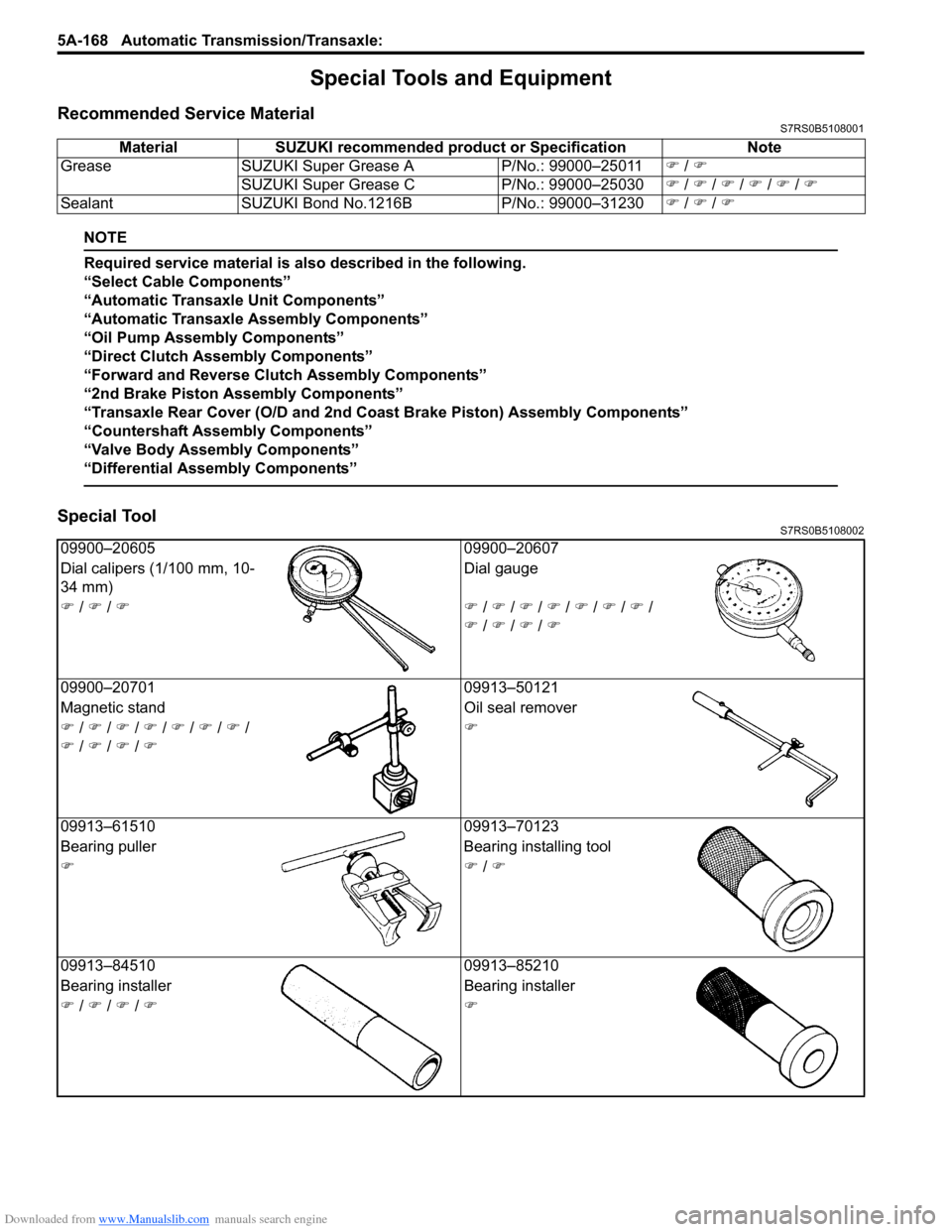
09900–20605 09900–20607
Dial calipers (1/100 mm, 10-
34 mm) Dial gauge
�) / �) / �)�) / �) / �) / �) / �) / �) / �) /
�) / �) / �) / �)
09900–20701 09913–50121
Magnetic stand Oil seal remover
�) / �) / �) / �) / �) / �) / �) /
�) / �) / �) / �) �)
09913–61510 09913–70123
Bearing puller Bearing installing tool
�)�) / �)
09913–84510 09913–85210
Bearing installer Bearing installer
�) / �) / �) / �)�)
Page 858 of 1496
Downloaded from www.Manualslib.com manuals search engine 5C-6 Clutch:
Clutch Fluid Pipe Removal and InstallationS7RS0B5306007
Removal
CAUTION!
Do not allow fluid to get on painted surface. It
may cause painted surface damage.
1) Remove dust and dirt from each joint of pipe to be disconnected and clean around brake master
cylinder reservoir cap.
2) Take out fluid with syringe or such from brake master cylinder reservoir.
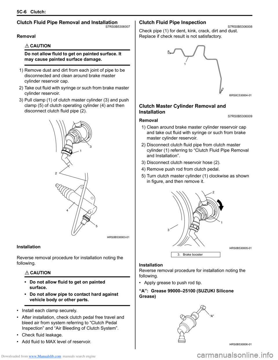
3) Pull clamp (1) of clutch master cylinder (3) and push clamp (5) of clutch operating cylinder (4) and then
disconnect clutch fluid pipe (2).
Installation
Reverse removal procedure for installation noting the
following.
CAUTION!
• Do not allow fluid to get on painted surface.
• Do not allow pipe to contact hard against vehicle body or other parts.
• Install each clamp securely.
• After installation, check clutch pedal free travel and bleed air from system referring to “Clutch Pedal
Inspection” and “Air Blee ding of Clutch System”.
• Check fluid leakage.
• Add fluid to MAX level of reservoir.
Clutch Fluid Pipe InspectionS7RS0B5306008
Check pipe (1) for dent, kink, crack, dirt and dust.
Replace if check result is not satisfactory.
Clutch Master Cylinder Removal and
Installation
S7RS0B5306009
Removal 1) Clean around brake master cylinder reservoir cap and take out fluid with syringe or such from brake
master cylinder reservoir.
2) Disconnect clutch fluid pipe from clutch master cylinder (1) referring to “C lutch Fluid Pipe Removal
and Installation”.
3) Disconnect clutch reservoir hose (2).
4) Remove push rod from clutch pedal.
5) Turn clutch master cylinder (1) clockwise as shown in figure, and then remove it.
Installation
Reverse removal procedure for installation noting the
following.
• Apply grease to push rod tip.
“A”: Grease 99000–25100 (SUZUKI Silicone
Grease)
31
2
5
4
I4RS0B530003-01
3. Brake booster
1
I6RS0C530004-01
1
2
3
I4RS0B530005-01
“A”
I4RS0B530006-01
Page 873 of 1496
Downloaded from www.Manualslib.com manuals search engine Steering Wheel and Column: 6B-2
Diagnostic Information and Procedures
Checking Steering Column for Accident
Damage
S7RS0B6204001
NOTE
Vehicles involved in accidents resulting in
body damage, where steering column has
been impacted or air bag deployed may have
a damaged or misaligned steering column.
Checking Procedure
NOTE
The steering column used in each vehicle is
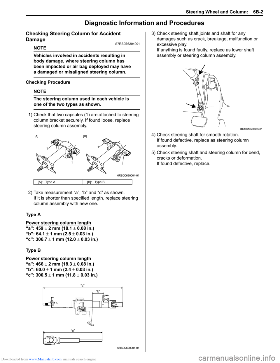
one of the two types as shown.
1) Check that two capsules (1) are attached to steering column bracket securely. If found loose, replace
steering column assembly.
2) Take measurement “a”, “b” and “c” as shown. If it is shorter than spec ified length, replace steering
column assembly with new one.
Ty p e A
Power steering column length
“a”: 459 ± 2 mm (18.1 ± 0.08 in.)
“b”: 64.1 ± 1 mm (2.5 ± 0.03 in.)
“c”: 306.7 ± 1 mm (12.0 ± 0.03 in.)
Ty p e B
Power steering column length
“a”: 466 ± 2 mm (18.3 ± 0.08 in.)
“b”: 60.0 ± 1 mm (2.4 ± 0.03 in.)
“c”: 300.5 ± 1 mm (11.8 ± 0.03 in.) 3) Check steering shaft joints and shaft for any
damages such as crack, breakage, malfunction or
excessive play.
If anything is found faulty, replace as lower shaft
assembly or steering column assembly.
4) Check steering shaft for smooth rotation. If found defective, replace as steering column
assembly.
5) Check steering shaft and steering column for bend, cracks or deformation.
If found defective, replace.
[A]: Type A [B]: Type B
[A] [B]
1
1
1
1
I6RS0C620004-01
I6RS0C620001-01
I4RS0A620003-01
Page 880 of 1496
Downloaded from www.Manualslib.com manuals search engine 6B-9 Steering Wheel and Column:
Ignition Switch Cylinder Assembly Removal
and Installation (Non- Keyless Start Model)
S7RS0B6206008
Removal1) Disconnect negative (–) cable at battery.
2) Disable air bag system referring to “Disabling Air Bag System in Section 8B”.
3) Remove steering column upper and lower covers.
4) Remove immobilizer co ntrol module referring to
“Immobilizer Control Modu le (ICM) Removal and
Installation in Section 10C”.
5) Remove ignition switch cy linder assembly as follows.
a) Turn ignition key to “ACC” position.
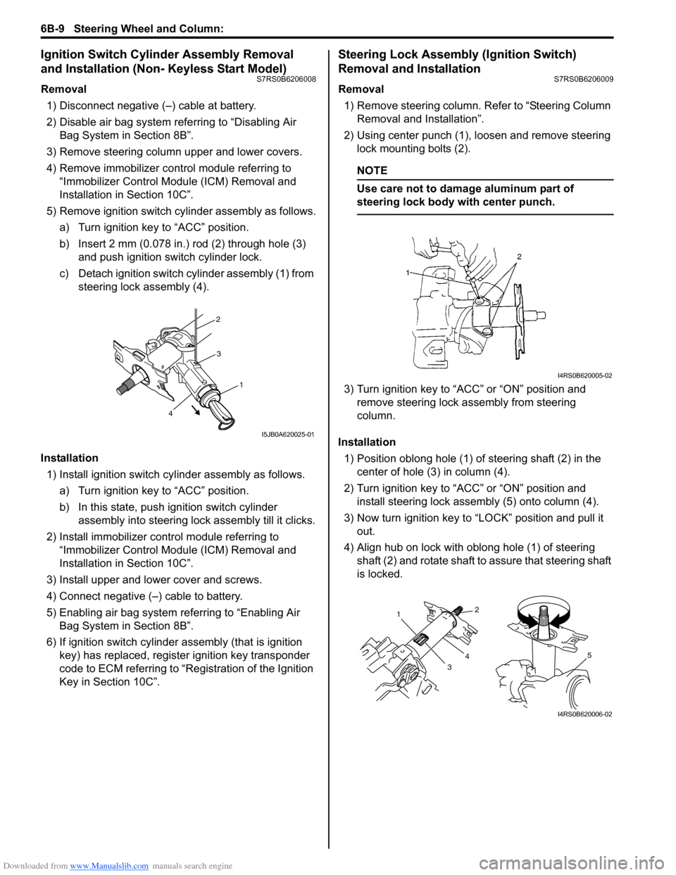
b) Insert 2 mm (0.078 in.) rod (2) through hole (3) and push ignition switch cylinder lock.
c) Detach ignition switch cylinder assembly (1) from steering lock assembly (4).
Installation 1) Install ignition switch cy linder assembly as follows.
a) Turn ignition key to “ACC” position.
b) In this state, push ignition switch cylinder assembly into steering lock assembly till it clicks.
2) Install immobilizer cont rol module referring to
“Immobilizer Control Modu le (ICM) Removal and
Installation in Section 10C”.
3) Install upper and lower cover and screws.
4) Connect negative (–) cable to battery.
5) Enabling air bag system referring to “Enabling Air Bag System in Section 8B”.
6) If ignition switch cylinder assembly (that is ignition
key) has replaced, register ignition key transponder
code to ECM referring to “R egistration of the Ignition
Key in Section 10C”.
Steering Lock Assembly (Ignition Switch)
Removal and Installation
S7RS0B6206009
Removal
1) Remove steering column. Refer to “Steering Column
Removal and Installation”.
2) Using center punch (1), loosen and remove steering lock mounting bolts (2).
NOTE
Use care not to damage aluminum part of
steering lock body with center punch.
3) Turn ignition key to “ACC” or “ON” position and remove steering lock a ssembly from steering
column.
Installation 1) Position oblong hole (1) of steering shaft (2) in the center of hole (3) in column (4).
2) Turn ignition key to “ACC” or “ON” position and install steering lock assemb ly (5) onto column (4).
3) Now turn ignition key to “LOCK” position and pull it out.
4) Align hub on lock with oblong hole (1) of steering shaft (2) and rotate shaft to assure that steering shaft
is locked.
2
3
1
4
I5JB0A620025-01
I4RS0B620005-02
1
32
4
5
I4RS0B620006-02
Page 894 of 1496
Downloaded from www.Manualslib.com manuals search engine 6C-12 Power Assisted Steering System:
Scan Tool Data Definitions
Battery Voltage
This parameter indicates battery positive voltage.
TQS Power Supply (Torque Sensor Power Supply, V)
This parameter indicates the power supply voltage which
the P/S control module supplies to the torque sensor.
TQS Main Torque (Torque Sensor Main Torque, N ⋅m)
The torque sensor is installed to detect the steering force
and the steering directio n. It consists of two
potentiometers and the main torque sensor is one of
these.
TQS Sub Torque (Torque Sensor Sub Torque, N ⋅m)
The torque sensor is installed to detect the steering force
and the steering directio n. It consists of two
potentiometers and the sub-torque sensor is one of
these. Its output characteristics are compared with those
of the main torque sensor.
Assist Torque (N ⋅m)
This parameter is an internal parameter of the P/S
control module. It is obtained by computing the torque
sensor input signal. Motor Control (Motor Control Current, A)
Based on the input signal, the P/S control module
determines the assist amount
and controls the current to
the motor suitable for that a ssist amount. This parameter
indicates that control value.
Motor Monitor (Motor Monitor Current, A)
This parameter indicates the actually measured value of
the current flowing to the motor. The motor circuit
condition is diagnosed by co mparing this parameter with
“Motor Control” parameter described previously.
Vehicle Speed (km/h, MPH)
Vehicle speed signal is fed from BCM. P/S control
module determines the amount of power assist based on
this vehicle speed signal and the torque sensor signal.
Engine Speed (rpm)
Engine speed signal is fed from the ECM so that it can
be used for trouble diagnos is of the electric power
steering system.
Motor Volt (V)
This parameter indicates the voltage between motor
terminals.
Ignition switch (ON, OFF)
This parameter indicates the condition of the power
supply through the ignition switch.
Visual InspectionS7RS0B6304007
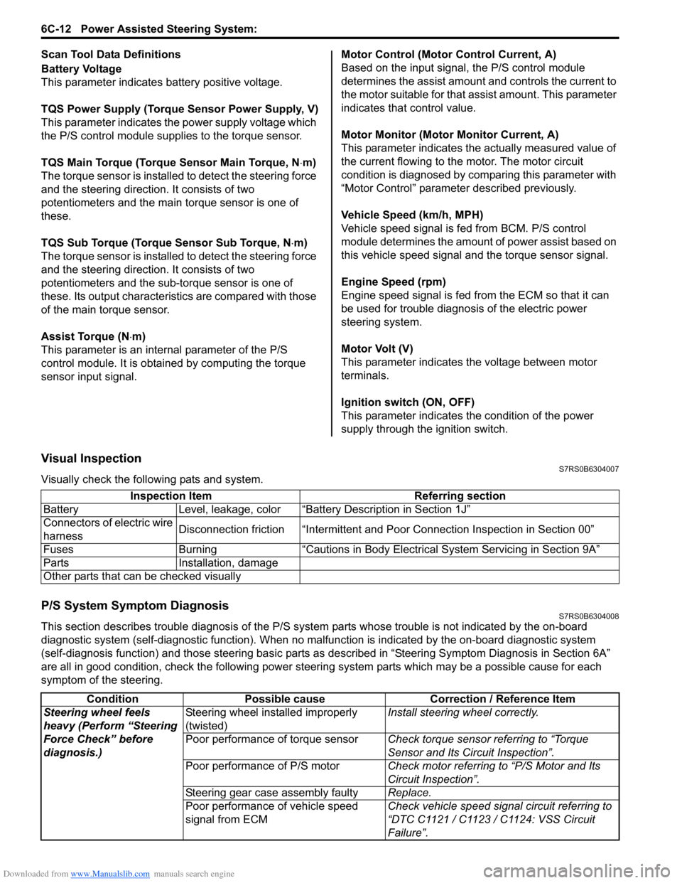
Visually check the following pats and system.
P/S System Symptom DiagnosisS7RS0B6304008
This section describes trouble diagnosis of the P/S system parts whose trouble is not indicated by the on-board
diagnostic system (self-diagnostic functi on). When no malfunction is indicated by the on-board diagnostic system
(self-diagnosis function) and those stee ring basic parts as described in “Steering Symptom Diagnosis in Section 6A”
are all in good condition, check the following power steer ing system parts which may be a possible cause for each
symptom of the steering. Inspection Item Referring section
Battery Level, leakage, color “Batte ry Description in Section 1J”
Connectors of electric wire
harness Disconnection friction “Intermittent and Poor
Connection Inspection in Section 00”
Fuses Burning “Cautions in Body Electric al System Servicing in Section 9A”
Parts Installation, damage
Other parts that can be checked visually
Condition Possible cause Correction / Reference Item
Steering wheel feels
heavy (Perform “Steering
Force Check” before
diagnosis.) Steering wheel installed improperly
(twisted)
Install steering wheel correctly.
Poor performance of torque sensor Check torque sensor referring to “Torque
Sensor and Its Circuit Inspection”.
Poor performance of P/S motor Check motor referring to “P/S Motor and Its
Circuit Inspection”.
Steering gear case assembly faulty Replace.
Poor performance of vehicle speed
signal from ECM Check vehicle speed signal circuit referring to
“DTC C1121 / C1123 / C1124: VSS Circuit
Failure”.
Page 896 of 1496
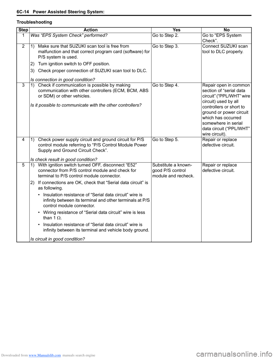
Downloaded from www.Manualslib.com manuals search engine 6C-14 Power Assisted Steering System:
TroubleshootingStep Action Yes No 1 Was “EPS System Check” performed? Go to Step 2. Go to “EPS System
Check”.
2 1) Make sure that SUZUKI scan tool is free from malfunction and that correct program card (software) for
P/S system is used.
2) Turn ignition switch to OFF position.
3) Check proper connection of SUZUKI scan tool to DLC.
Is connection in good condition? Go to Step 3. Connect SUZUKI scan
tool to DLC properly.
3 1) Check if communication is possible by making communication with other controllers (ECM, BCM, ABS
or SDM) or other vehicles.
Is it possible to communic ate with the other controllers? Go to Step 4. Repair open in common
section of “serial data
circuit” (“PPL/WHT” wire
circuit) used by all
controllers or short to
ground or power circuit
which has occurred
somewhere in serial
data circuit (“PPL/WHT”
wire circuit).
4 1) Check power supply circuit and ground circuit for P/S control module referring to “P/S Control Module Power
Supply and Ground Circuit Check”.
Is check result in good condition? Go to Step 5. Repair or replace
defective circuit.
5 1) With ignition switch turned OFF, disconnect “E52” connector from P/S control module and check for
terminal to P/S control module connector.
2) If connections are OK, check t hat “Serial data circuit” is
as following.
• Insulation resistance of “Serial data circuit” wire is infinity between its terminal and other terminals at P/S
control module connector.
• Wiring resistance of “Seria l data circuit” wire is less
than 1 Ω.
• Insulation resistance of “Serial data circuit” wire is infinity between its terminal and vehicle body ground.
Is circuit in good condition? Substitute a known-
good P/S control
module and recheck.
Repair or replace
defective circuit.