200 SUZUKI SWIFT 2006 2.G Service Workshop Manual
[x] Cancel search | Manufacturer: SUZUKI, Model Year: 2006, Model line: SWIFT, Model: SUZUKI SWIFT 2006 2.GPages: 1496, PDF Size: 34.44 MB
Page 1159 of 1496
Downloaded from www.Manualslib.com manuals search engine Air Bag System: 8B-121
Deployment / Activation Inside of Vehicle
When the vehicle will be destroyed, or salvaged for
component parts, deploy the air bag modules and/or
activate seat belt pretensioners installed on vehicle.
NOTE
If equipped with the seat belt pretensioners,
activate both side of seat belt pretensioners
at the same time when using special tool (C).
1) Turn ignition switch to LOCK position, remove key
and put on safety glasses.
2) Remove all loose objects from front seats and instrument panel.
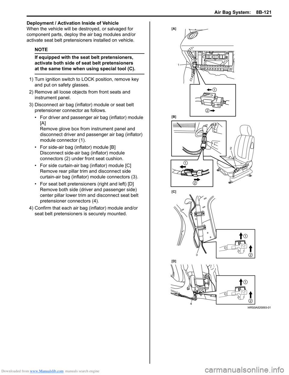
3) Disconnect air bag (inflator) module or seat belt pretensioner connector as follows.
• For driver and passenger air bag (inflator) module [A]
Remove glove box from instrument panel and
disconnect driver and passenger air bag (inflator)
module connector (1).
• For side-air bag (inflator) module [B] Disconnect side-air bag (inflator) module
connectors (2) under front seat cushion.
• For side curtain-air bag (inflator) module [C] Remove rear pillar trim and disconnect side
curtain-air bag (inflator) module connectors (3).
• For seat belt pretensioners (right and left) [D] Remove both side (driver and passenger side)
center pillar lower trim an d disconnect seat belt
pretensioner connectors (4).
4) Confirm that each air bag (inflator) module and/or seat belt pretensioners is securely mounted.
[A]
[B]
[C]
[D]
2
1
3
4
1
2
1
2
1
2
1
2
I4RS0A820093-01
Page 1160 of 1496
Downloaded from www.Manualslib.com manuals search engine 8B-122 Air Bag System:
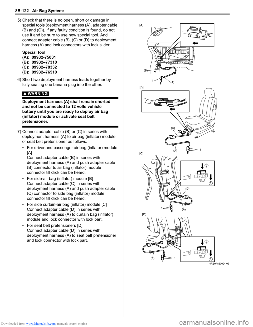
5) Check that there is no open, short or damage in special tools (deployment harness (A), adapter cable
(B) and (C)). If any faulty condition is found, do not
use it and be sure to use new special tool. And
connect adapter cable (B), (C) or (D) to deployment
harness (A) and lock connectors with lock slider.
Special tool
(A): 09932-75031
(B): 09932–77310
(C): 09932–78332
(D): 09932–76510
6) Short two deployment harness leads together by fully seating one banana plug into the other.
WARNING!
Deployment harness (A) shall remain shorted
and not be connected to 12 volts vehicle
battery until you are ready to deploy air bag
(inflator) module or activate seat belt
pretensioner.
7) Connect adapter cable (B) or (C) in series with deployment harness (A) to air bag (inflator) module
or seat belt pretensioner as follows.
• For driver and passenger air bag (inflator) module [A]
Connect adapter cable (B) in series with
deployment harness (A) and push adapter cable
(B) connector to air bag (inflator) module
connector till click can be heard.
• For side-air bag (inflator) module [B] Connect adapter cable (C) in series with
deployment harness (A) and push adapter cable
(C) connector to side bag (inflator) module
connector till click can be heard.
• For side curtain-air bag (inflator) module [C] Connect adapter cable (D) in series with
deployment harness (A) to curtain bag (inflator)
module and lock connector with lock part.
• For seat belt pretensioners [D] Connect adapter cable (D) in series with
deployment harness (A) to seat belt pretensioner
and lock connector with lock part.
[A]
[C]
[D]
1
2
1
2
1
(B) (A)
[B]
1
(C)
(A)
1
(D)
(A)
(A)
(D)
1
I4RS0A820094-02
Page 1161 of 1496
Downloaded from www.Manualslib.com manuals search engine Air Bag System: 8B-123
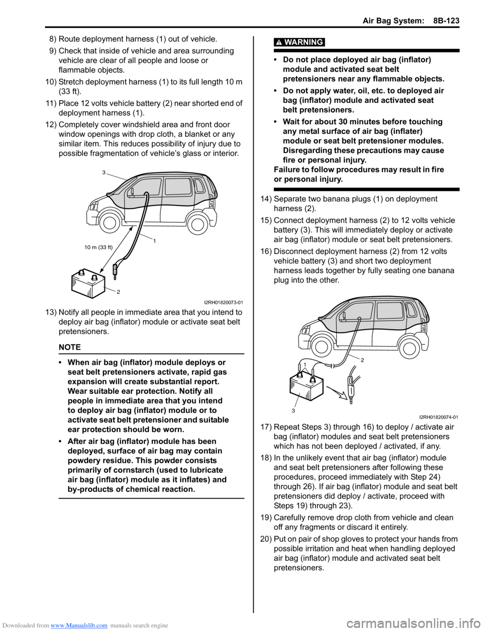
8) Route deployment harness (1) out of vehicle.
9) Check that inside of vehicle and area surrounding vehicle are clear of all people and loose or
flammable objects.
10) Stretch deployment harness (1) to its full length 10 m (33 ft).
11) Place 12 volts vehicle battery (2) near shorted end of deployment harness (1).
12) Completely cover windshield area and front door window openings with drop cloth, a blanket or any
similar item. This reduces possibility of injury due to
possible fragmentation of vehicle’s glass or interior.
13) Notify all people in immediate area that you intend to deploy air bag (inflator) module or activate seat belt
pretensioners.
NOTE
• When air bag (inflator) module deploys or seat belt pretensioners activate, rapid gas
expansion will create substantial report.
Wear suitable ear protection. Notify all
people in immediate area that you intend
to deploy air bag (inflator) module or to
activate seat belt pretensioner and suitable
ear protection should be worn.
• After air bag (inflator) module has been deployed, surface of air bag may contain
powdery residue. This powder consists
primarily of cornstarch (used to lubricate
air bag (inflator) module as it inflates) and
by-products of chemical reaction.
WARNING!
• Do not place deployed air bag (inflator) module and activated seat belt
pretensioners near any flammable objects.
• Do not apply water, oil, etc. to deployed air bag (inflator) module and activated seat
belt pretensioners.
• Wait for about 30 minutes before touching any metal surface of air bag (inflater)
module or seat belt pretensioner modules.
Disregarding these precautions may cause
fire or personal injury.
Failure to follow procedures may result in fire
or personal injury.
14) Separate two banana plugs (1) on deployment harness (2).
15) Connect deployment harness (2) to 12 volts vehicle battery (3). This will immedi ately deploy or activate
air bag (inflator) module or seat belt pretensioners.
16) Disconnect deployment harness (2) from 12 volts vehicle battery (3) and short two deployment
harness leads together by fully seating one banana
plug into the other.
17) Repeat Steps 3) through 16) to deploy / activate air bag (inflator) modules and seat belt pretensioners
which has not been deployed / activated, if any.
18) In the unlikely event that air bag (inflator) module and seat belt pretensioners after following these
procedures, proceed immediately with Step 24)
through 26). If air bag (inflator) module and seat belt
pretensioners did deploy / activate, proceed with
Steps 19) through 23).
19) Carefully remove drop cloth from vehicle and clean off any fragments or discard it entirely.
20) Put on pair of shop gloves to protect your hands from
possible irritation and heat when handling deployed
air bag (inflator) module and activated seat belt
pretensioners.
10 m (33 ft) 1
2
3
I2RH01820073-01
1
3 2
I2RH01820074-01
Page 1162 of 1496
Downloaded from www.Manualslib.com manuals search engine 8B-124 Air Bag System:
21) Disconnect adapter cable (special tool) from air bag (inflator) module or seat belt pretensioner as soon as
possible. This will preven t adapter cable (special
tool) from damage due to possible contact with hot
air bag (inflator) module or hot seat belt
pretensioner.
22) Check adapter cable connector as follows. Adapter cable connector (special tool) is designed to
be reused. However it should be inspected for
damage after deployment and replaced if necessary.
23) With air bag (inflator) modules deployed and seat belt pretensioners acti vated, vehicle may be
scrapped in the same manner as non-air bag system
/ seat belt pretensioner equipped vehicle.
NOTE
Remaining steps are to be followed in the
unlikely event that air bag (inflator) module
did not deploy or seat belt pretensioner did
not activate.
24) Remove undeployed air bag (inflator) module(s) and/ or inactivated seat belt pretensioner(s) from vehicle.
For driver air bag (inflator) module, refer to “Driver
Air Bag (Inflator) Module Removal and Installation”.
For passenger air bag (inflator) module, refer to
“Passenger Air Bag (Inflator) Module Removal and
Installation”. For seat belt pretensioner, refer to
“Front Seat Belt Removal an d Installation in Section
8A”.
25) Temporarily store undeployed air bag (inflator) module referring to “Precautions on Service and
Diagnosis of Air Bag System” for details.
26) Contact your local distribu tor for further assistance.
Deployed Air Bag (Inflator) Module and
Activated Seat Belt Pretensioner Disposal
S7RS0B8206019
WARNING!
Failure to follow proper air bag (inflator)
module and seat belt pretensioner disposal
procedures can result in air bag deployment
and pretensioner activation which may cause
personal injury. The undeployed air bag
(inflator) module and the inactivated seat belt
pretensioner must not be disposed of
through normal refuse channels.
The undeployed air bag (inflator) module and
the inactivated seat belt pretensioner
contains substances that can cause severe
illness or personal injury if the sealed
container is damaged during disposal.
Deployed air bag (inflator) module and the activated seat
belt pretensioner can be disposed of through normal
refuse channels just like any other parts. For their
disposal, however, the following points should be noted.
• The air bag (inflator) module and the seat belt
pretensioner immediately after deployment / activation
is very hot. Wait for 30 minu tes to cool it off before
handling it.
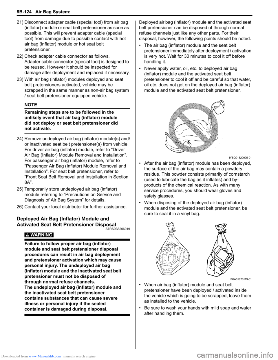
• Never apply water, oil, etc. to deployed air bag (inflator) module and the activated seat belt
pretensioner to cool it off and be careful so that water,
oil etc. does not get on the deployed air bag (inflator)
module and the activated seat belt pretensioner.
• After the air bag (inflator) module has been deployed, the surface of the air bag may contain a powdery
residue. This powder consists primarily of cornstarch
(used to lubricate the bag as it inflates) and by-
products of the chemical reaction. As with many
service procedures, you should wear gloves and
safety glasses.
• When disposing of the deployed air bag (inflator) module and the activated seat belt pretensioner, be
sure to seal it in a vinyl bag.
• When air bag (inflator) module and seat belt pretensioner have been deployed / activated inside
the vehicle which is going to be scrapped, leave them
as installed to the vehicle.
• Be sure to wash your hand s with mild soap and water
after handling them.
IYSQ01820095-01
I3JA01820119-01
Page 1163 of 1496
Downloaded from www.Manualslib.com manuals search engine Air Bag System: 8B-125
Specifications
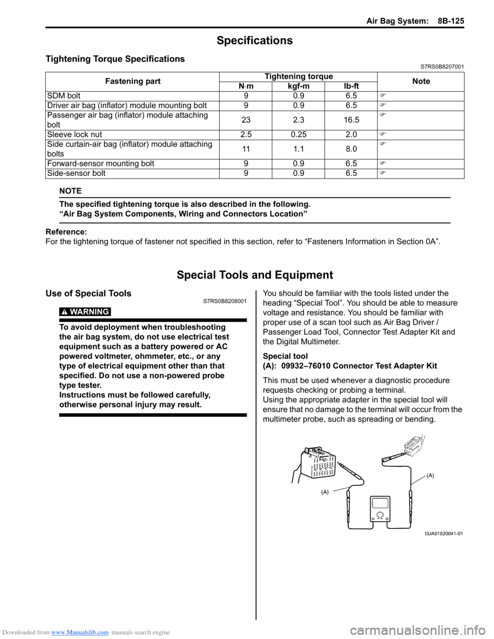
Tightening Torque SpecificationsS7RS0B8207001
NOTE
The specified tightening torque is also described in the following.
“Air Bag System Components, Wiring and Connectors Location”
Reference:
For the tightening torque of fastener not specified in this section, refer to “Fasteners Information in Section 0A”.
Special Tools and Equipment
Use of Special ToolsS7RS0B8208001
WARNING!
To avoid deployment when troubleshooting
the air bag system, do not use electrical test
equipment such as a battery powered or AC
powered voltmeter, ohmmeter, etc., or any
type of electrical equipment other than that
specified. Do not use a non-powered probe
type tester.
Instructions must be followed carefully,
otherwise personal injury may result.
You should be familiar with the tools listed under the
heading “Special Tool”. You should be able to measure
voltage and resistance. You should be familiar with
proper use of a scan tool such as Air Bag Driver /
Passenger Load Tool, Connector Test Adapter Kit and
the Digital Multimeter.
Special tool
(A): 09932–76010 Connector Test Adapter Kit
This must be used whenever a diagnostic procedure
requests checking or probing a terminal.
Using the appropriate adapter in the special tool will
ensure that no damage to the terminal will occur from the
multimeter probe, such as spreading or bending.
Fastening part
Tightening torque
Note
N ⋅mkgf-mlb-ft
SDM bolt 9 0.9 6.5 �)
Driver air bag (inflator) module mounting bolt 9 0.9 6.5 �)
Passenger air bag (inflator) module attaching
bolt 23 2.3 16.5�)
Sleeve lock nut 2.5 0.25 2.0 �)
Side curtain-air bag (inflator) module attaching
bolts 11 1.1 8.0�)
Forward-sensor mounting bolt 9 0.9 6.5 �)
Side-sensor bolt 9 0.9 6.5 �)
I3JA01820041-01
Page 1164 of 1496
Downloaded from www.Manualslib.com manuals search engine 8B-126 Air Bag System:
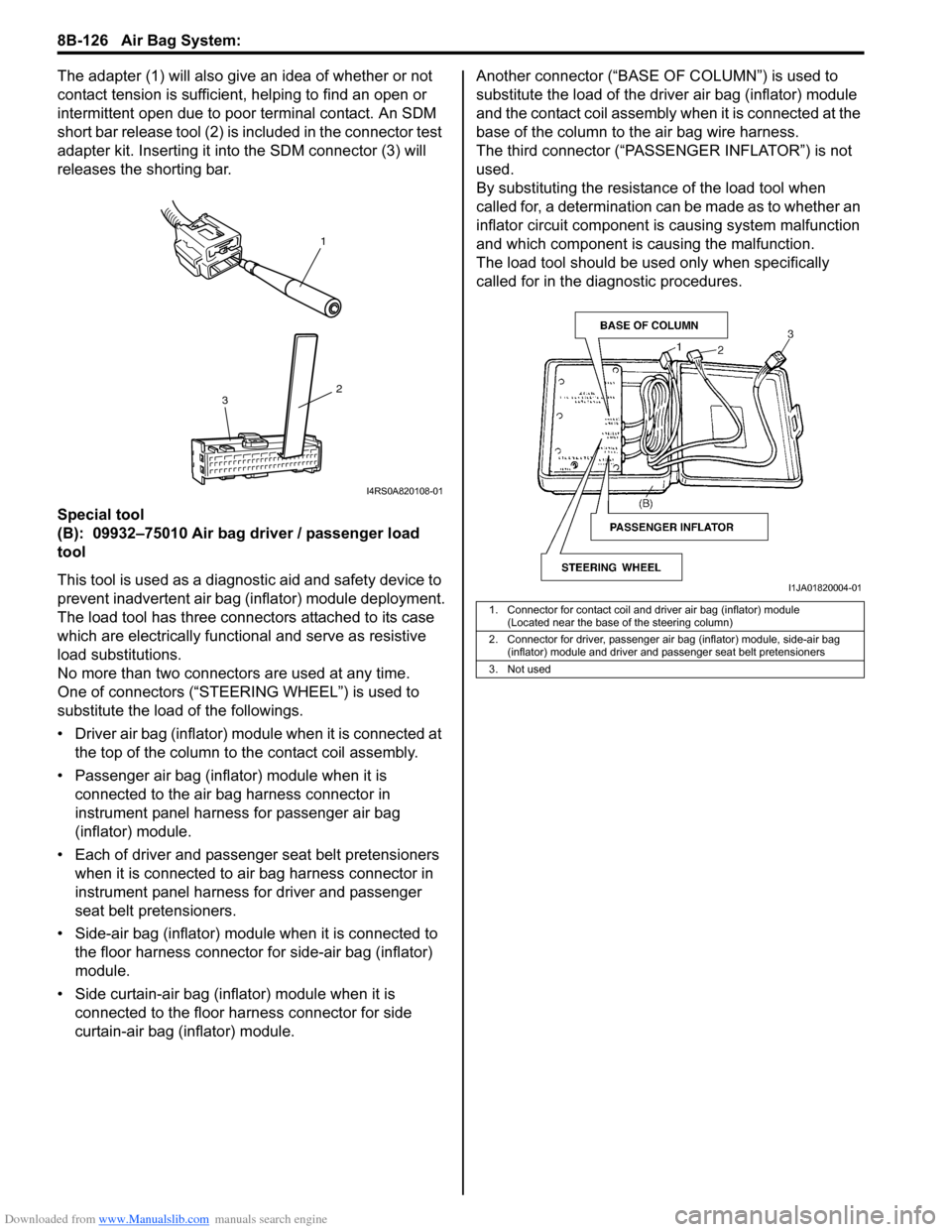
The adapter (1) will also give an idea of whether or not
contact tension is sufficient, helping to find an open or
intermittent open due to poor terminal contact. An SDM
short bar release tool (2) is included in the connector test
adapter kit. Inserting it in to the SDM connector (3) will
releases the shorting bar.
Special tool
(B): 09932–75010 Air bag driver / passenger load
tool
This tool is used as a diagno stic aid and safety device to
prevent inadvertent air bag (inflator) module deployment.
The load tool has three connectors attached to its case
which are electrically functional and serve as resistive
load substitutions.
No more than two connectors are used at any time.
One of connectors (“STEER ING WHEEL”) is used to
substitute the load of the followings.
• Driver air bag (inflator) module when it is connected at the top of the column to the contact coil assembly.
• Passenger air bag (inflator) module when it is connected to the air bag harness connector in
instrument panel harness for passenger air bag
(inflator) module.
• Each of driver and passen ger seat belt pretensioners
when it is connected to air bag harness connector in
instrument panel harness for driver and passenger
seat belt pretensioners.
• Side-air bag (inflator) module when it is connected to the floor harness connector for side-air bag (inflator)
module.
• Side curtain-air bag (inflator) module when it is connected to the floor harness connector for side
curtain-air bag (inflator) module. Another connec
tor (“BASE OF COLUMN ”) is used to
substitute the load of the driver air bag (inflator) module
and the contact coil assembly when it is connected at the
base of the column to the air bag wire harness.
The third connector (“PASSENGER INFLATOR”) is not
used.
By substituting the resistan ce of the load tool when
called for, a determination can be made as to whether an
inflator circuit component is causing system malfunction
and which component is causing the malfunction.
The load tool should be used only when specifically
called for in the diagnostic procedures.
1
2
3
I4RS0A820108-01
1. Connector for contact coil and driver air bag (inflator) module
(Located near the base of the steering column)
2. Connector for driver, passenger air bag (inflator) module, side-air bag (inflator) module and driver and passenger seat belt pretensioners
3. Not used
I1JA01820004-01
Page 1274 of 1496
Downloaded from www.Manualslib.com manuals search engine 9A-103 Wiring Systems:
List of Connector
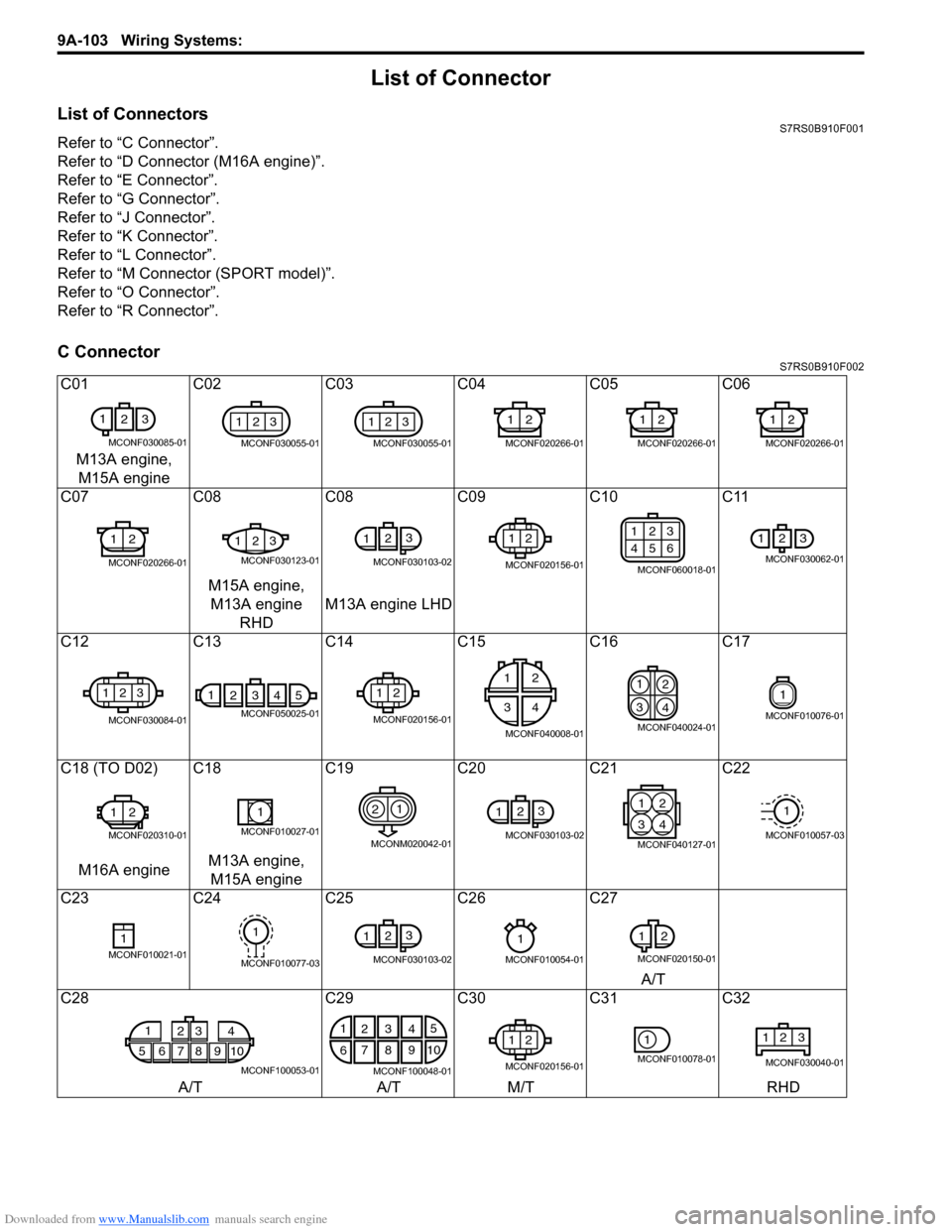
List of ConnectorsS7RS0B910F001
Refer to “C Connector”.
Refer to “D Connector (M16A engine)”.
Refer to “E Connector”.
Refer to “G Connector”.
Refer to “J Connector”.
Refer to “K Connector”.
Refer to “L Connector”.
Refer to “M Connector (SPORT model)”.
Refer to “O Connector”.
Refer to “R Connector”.
C ConnectorS7RS0B910F002
C01C02C03 C04 C05 C06
M13A engine, M15A engine
C07 C08C08 C09 C10 C11
M15A engine, M13A engine RHD M13A engine LHD
C12 C13C14 C15 C16 C17
C18 (TO D02) C18 C19C20C21C22
M16A engine M13A engine,
M15A engine
C23 C24C25 C26 C27
A/T
C28 C29C30C31C32
A/T A/TM/T RHD
1
23
MCONF030085-01
123
MCONF030055-01
123
MCONF030055-01
12
MCONF020266-01
12
MCONF020266-01
12
MCONF020266-01
12
MCONF020266-01
123
MCONF030123-01
123
MCONF030103-02
12
MCONF020156-01
123
456
MCONF060018-01
123
MCONF030062-01
123
MCONF030084-01
14325
MCONF050025-01
12
MCONF020156-01
12
34
MCONF040008-01
1
2
3 4
MCONF040024-01
1
MCONF010076-01
12
MCONF020310-01
1
MCONF010027-01
21
MCONM020042-01
12
3
MCONF030103-02
21
43
MCONF040127-01
1
MCONF010057-03
1MCONF010021-01
1
MCONF010077-03
123
MCONF030103-02
1
MCONF010054-01
1
2
MCONF020150-01
1
5678910 23 4
MCONF100053-01
1
2 5
6 7
103
84
9
MCONF100048-01
12
MCONF020156-01
1
MCONF010078-01
123
MCONF030040-01
Page 1275 of 1496
Downloaded from www.Manualslib.com manuals search engine Wiring Systems: 9A-104
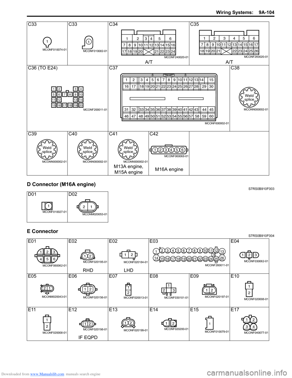
D Connector (M16A engine)S7RS0B910F003
E ConnectorS7RS0B910F004
C33C33C34 C35
A/T A/T
C36 (TO E24) C37 C38
C39 C40C41 C42
M13A engine, M15A engine M16A engine
D01 D02
E01 E02E02E03 E04
RHD LHD
E05 E06E07E08 E09E10
E11 E12E13 E14 E15 E17
IF EQPD
1
MCONF010074-01
1
MCONF010082-0117181920
7
1256
89101113141516
21222324
12
34
MCONF240020-01
181920 21
7 12345 68910
22232425
13141516
26
171112
MCONF260020-01
21
8
3
9765
131211
1819
4
10
14
20171615MCONF200011-01
12 3456
20 21
16 17 18 1978910
22 23 24 25 12
272613
28
31 32 33 34 35 36 50 51
46 47 48 49 37 38 39 40
52 53 54 5511
41
56
42
5743
5814 15 29 30
44 60 45
59
MCONF600002-01
Weld
splice
MCONN000002-01
Weld
splice
MCONN000002-01
Weld
splice
MCONN000002-01
Weld
splice
MCONN000002-01
1234 56
MCONF060068-01
1
MCONF010027-01
21
MCONM020053-01
1 2 3
4 5
6
MCONF060062-01
12
MCONF020195-01
12
MCONF020184-01
12345678910111213
14151617181920212223242526
MCONF260011-01
123
MCONF030062-01
21
MCONM020043-01
12
MCONF020156-01
1
2
MCONF020013-01
12 3
MCONF030101-01
21
MCONF020197-01
1
2
MCONF020008-01
1
2
MCONF020008-01
21
MCONF020198-01
12
MCONF020199-01
1
2
MCONF020200-01
1
MCONF010079-01
21
43
MCONF040077-01
Page 1276 of 1496
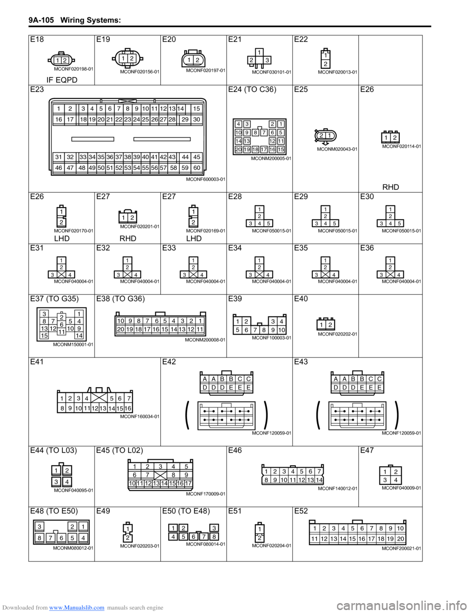
Downloaded from www.Manualslib.com manuals search engine 9A-105 Wiring Systems:
E18E19E20E21 E22
IF EQPD
E23 E24 (TO C36) E25E26
RHD
E26 E27E27E28 E29E30
LHD RHD LHD
E31 E32E33E34 E35E36
E37 (TO G35) E38 (TO G36) E39E40
E41 E42E43
E44 (TO L03) E45 (TO L02) E46E47
E48 (TO E50) E49 E50 (TO E48) E51E52
21
MCONF020198-01
12
MCONF020156-01
21
MCONF020197-01
12
3
MCONF030101-01
1
2
MCONF020013-01
123456
202116171819
78910
22232425
12
2726
13
28
313233343536
505146474849
37383940
52535455
11
41
56
42
57
43
58
1415
2930
44
60
45
59
MCONF600003-01
34
7
2
68910
121314
1716
1
5
11
15181920
MCONM200005-01
21
MCONM020043-01
21
MCONF020114-01
1
2
MCONF020170-01
21
MCONF020201-01
1
2
MCONF020169-01
1
2
345
MCONF050015-01
1
2
345
MCONF050015-01
1
2
345
MCONF050015-01
1
2
34
MCONF040004-01
1
2
34
MCONF040004-01
1
2
34
MCONF040004-01
1
2
34
MCONF040004-01
1
2
34
MCONF040004-01
1
2
34
MCONF040004-01
381371251015
14914
2611
MCONM150001-01
54 32 167910
20 19 18 17 16 15 14 13 12 118
MCONM200008-01
1 234
5 678 910
MCONF100003-01
21
MCONF020202-01
6
5
4
3
2
17
11
10
9
8 15
14
13
12 16
MCONF160034-01
CC
AABB
DE
DD
EE
MCONF120059-01
CC
AABB
DE
DD
EE
MCONF120059-01
12
34
MCONF040095-0110 1
6111415 16 171213
2
734
85
9
MCONF170009-01
12567
8
9 1011121314
34
MCONF140012-01
12
34
MCONF040009-01
21
7654
3
8
MCONM080012-01
1
2
MCONF020203-01
2
51
47 6
8
3
MCONF080014-01
1
2
MCONF020204-01
10
11 12 13 14 15 16 17 18 19 123456789
20
MCONF200021-01
Page 1277 of 1496
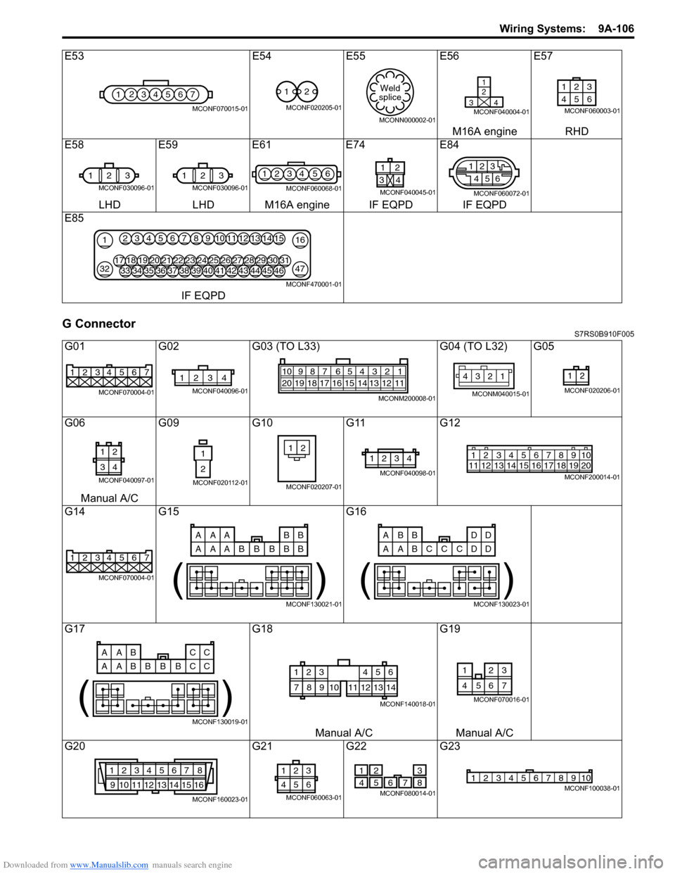
Downloaded from www.Manualslib.com manuals search engine Wiring Systems: 9A-106
G ConnectorS7RS0B910F005
E53E54E55 E56E57
M16A engine RHD
E58 E59E61E74 E84
LHD LHD M16A engine IF EQPD IF EQPD
E85
IF EQPD
G01 G02G03 (TO L33) G04 (TO L32) G05
G06 G09G10G11G12
Manual A/C
G14 G15 G16
G17 G18G19
Manual A/C Manual A/C
G20 G21G22G23
1234567
MCONF070015-01
12
MCONF020205-01
Weld
splice
MCONN000002-01
1
2
34
MCONF040004-01
123
46 5
MCONF060003-01
1 23
MCONF030096-01
123
MCONF030096-01
1234 56
MCONF060068-01
1
34
2
MCONF040045-01
2
5
46
13
MCONF060072-01
21
3247
163451213141567891011
3334353643444546373839404142181719202128293031222324252627
MCONF470001-01
1234567
MCONF070004-01
1234
MCONF040096-01
54 32 167910
20 19 18 17 16 15 14 13 12 118
MCONM200008-01
12
34
MCONM040015-01
12
MCONF020206-01
12
34
MCONF040097-01
1
2
MCONF020112-01
21
MCONF020207-01
1234
MCONF040098-01
125678911 12 13 14 15 16 17 18 1910
2034
MCONF200014-01
1234567
MCONF070004-01
AAA BB
AAA B
BB
BB
( )
MCONF130021-01
ABB DD
AAB D
CC
CD
( )
MCONF130023-01
AAB CC
AAB C
BB
BC
( )
MCONF130019-01
123
78910
456
11121314
MCONF140018-01
3
7654
21
MCONF070016-01
1234567 8
9 10111213141516
MCONF160023-01
3
21
654
MCONF060063-01
2
51
47 6
8
3
MCONF080014-01
12345678910MCONF100038-01