ron SUZUKI SWIFT 2006 2.G Service Workshop Manual
[x] Cancel search | Manufacturer: SUZUKI, Model Year: 2006, Model line: SWIFT, Model: SUZUKI SWIFT 2006 2.GPages: 1496, PDF Size: 34.44 MB
Page 1209 of 1496
Downloaded from www.Manualslib.com manuals search engine Wiring Systems: 9A-38
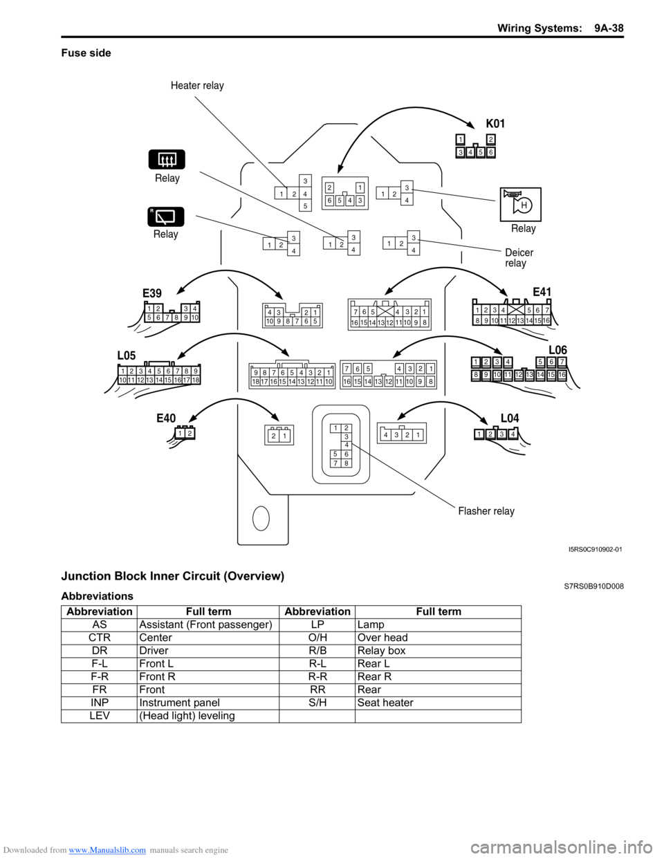
Fuse side
Junction Block Inner Circuit (Overview)S7RS0B910D008
Abbreviations
123
4 5
1 2 3
4 1
2 3
4 1
2 3
4
1 23
4
Heater relay
Relay
Deicer
relay
23412112
12 34 5 6 78 9 15 16 17 18
1110 12 13 14 4
3 561214
11
10 15
721
13
16
98
1
234
5 678 910
4321
10 987 656
5
4
3
2
17
11
10
9
8
15
14
13
12 16
987654321
13 12 11 10
1718 16 15 14
13
14
15
16
9
10
11
12 8
5
6
7 2
3
4 1
321
4
E39
L05
E40 L04L06
E41
H
Relay
Relay
12 34
6
5
8
7
4 3
5
6
1214 11 10
15
7
2
1
13
16 9 8
3456
12
K01
6543
21
Flasher relay
I5RS0C910902-01
Abbreviation Full term Abbreviation Full term
AS Assistant (Front passenger) LP Lamp
CTR Center O/H Over head
DR Driver R/B Relay box
F-L Front L R-L Rear L
F-R Front R R-R Rear R
FR Front RR Rear
INP Instrument panel S/H Seat heater
LEV (Head light) leveling
Page 1216 of 1496

Downloaded from www.Manualslib.com manuals search engine 9A-45 Wiring Systems:
System Circuit Diagram
System Circuit DiagramS7RS0B910E001
Refer to “A-1 Cranking System Circuit Diagram”.
Refer to “A-2 Charging System Circuit Diagram”.
Refer to “A-3 Ignition System Circuit Diagram”.
Refer to “A-4 Cooling System Circuit Diagram”.
Refer to “A-5 Engine and A/C Control System Circuit Diagram”.
Refer to “A-6 A/T Control System Circuit Diagram”.
Refer to “A-7 Immobilizer System Circuit Diagram”.
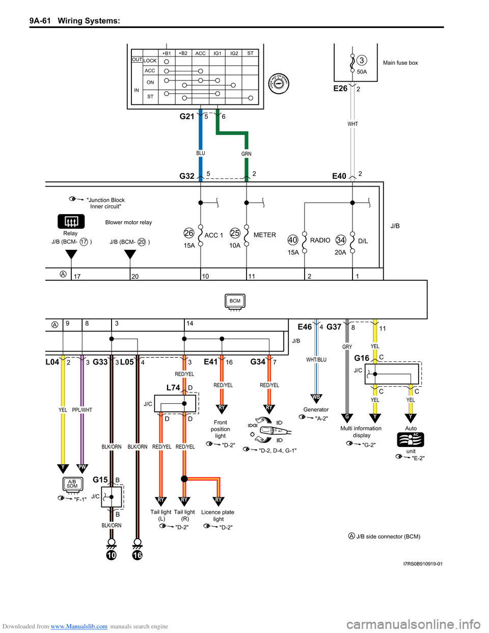
Refer to “A-8 Body Control System Circuit Diagram”.
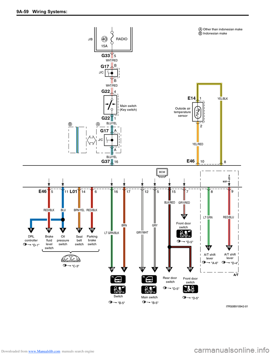
Refer to “B-1 Windshield Wiper and Washer Circuit Diagram”.
Refer to “B-2 Rear Wiper and Washer Circuit Diagram”.
Refer to “B-3 Rear Defogger Circuit Diagram”.
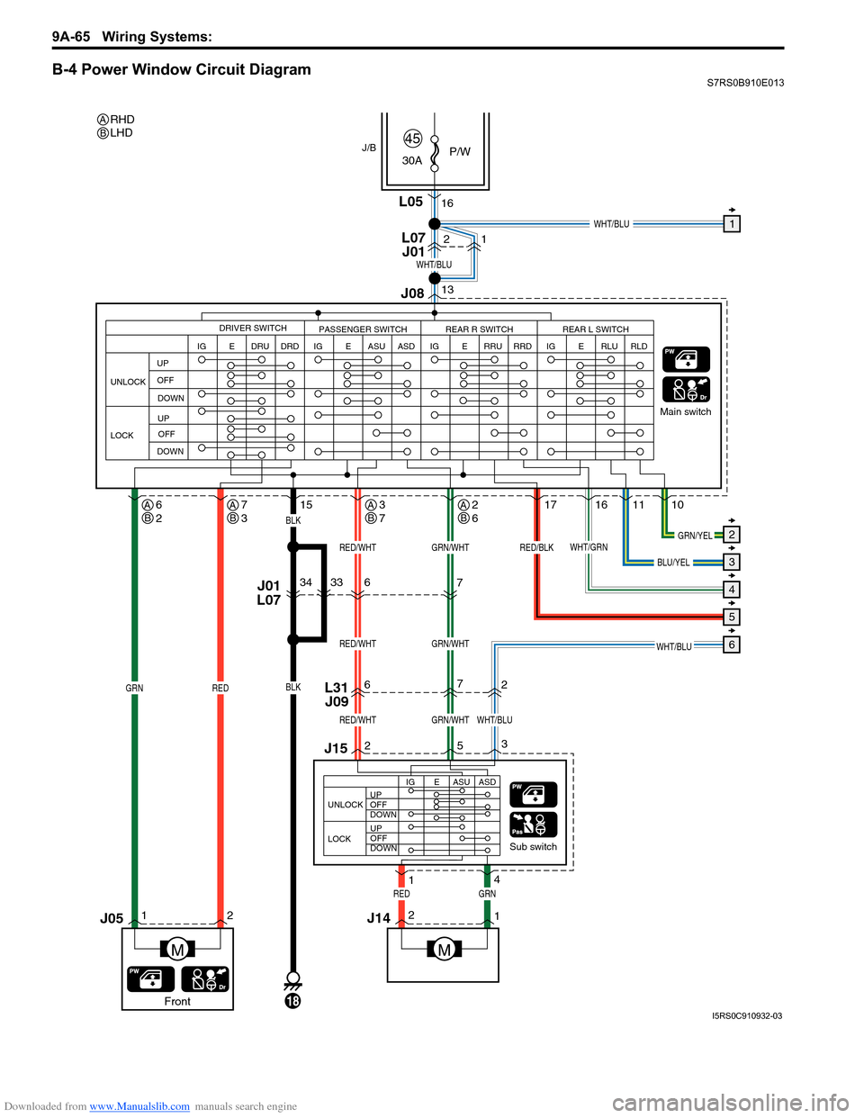
Refer to “B-4 Power Window Circuit Diagram”.
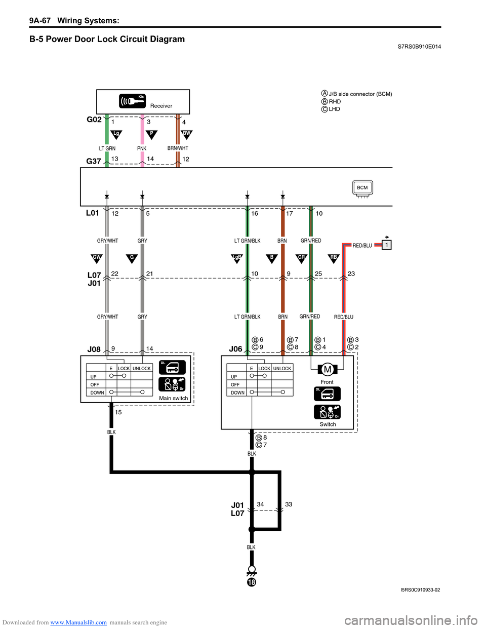
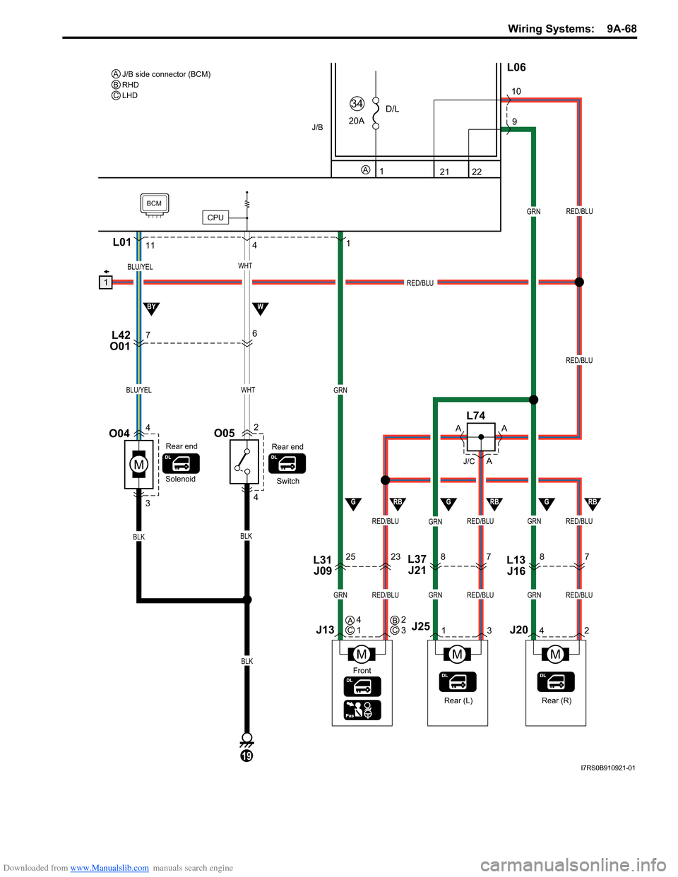
Refer to “B-5 Power Door Lock Circuit Diagram”.
Refer to “B-6 Power Mi rror Circuit Diagram”.
Refer to “B-7 Horn Circuit Diagram”.
Refer to “B-8 Seat Heater Circuit Diagram”.
Refer to “B-9 Keyless Star t System Circuit Diagram”.
Refer to “C-1 Combination Me ter Circuit Diagram (Meter)”.
Refer to “C-2 Combination Mete r Circuit Diagram (Indicator)”.
Refer to “C-3 Combination Meter Circuit Diagram (Warning Light)”.
Refer to “D-1 Headlight System Circuit Diagram”.
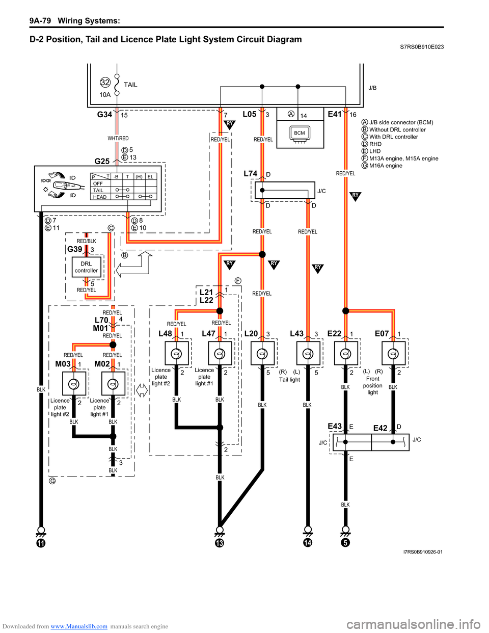
Refer to “D-2 Position, Tail and Licence Plate Light System Circuit Diagram”.
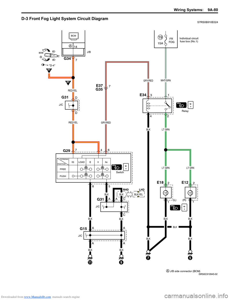
Refer to “D-3 Front Fog Light System Circuit Diagram”.
Refer to “D-4 Illumination Light System Circuit Diagram”.
Refer to “D-5 Interior Li ght System Circuit Diagram”.
Refer to “D-6 Turn Signal and Hazard Warning Light System Circuit Diagram”.
Refer to “D-7 Brake Light System Circuit Diagram”.
Refer to “D-8 Back-Up Light System Circuit Diagram”.
Refer to “D-9 Headlight Beam Leveling System Circuit Diagram”.
Refer to “D-10 Rear Fog Light Circuit Diagram”.
Refer to “E-1 Heater System Circuit Diagram”.
Refer to “E-2 Auto A/C System Circuit Diagram”.
Refer to “F-1 Air-Bag System Circuit Diagram”.
Refer to “F-2 Anti-Lock Brake System Circuit Diagram”.
Refer to “F-3 Electronic Stabilit y Program System Circuit Diagram”.
Refer to “F-4 Power Steeri ng System Circuit Diagram”.
Refer to “G-1 Audio Sy stem Circuit Diagram”.
Refer to “G-2 Multi Information Display / Accessory Socket System Circuit Diagram”.
Page 1230 of 1496
Downloaded from www.Manualslib.com manuals search engine 9A-59 Wiring Systems:
9
15 7
"D-5"
"A-6"
A/T
GRY/RED
RED/BLU
16
A A
B
BG37
BLU/YEL
BLU/YEL
J/C
G17
J/C
G17
G22
G22
1
4
Main switch
(Key switch)
RADIO
G335
15A
40
WHT/RED
WHT/RED
YEL/RED
YEL/BLK1E14
2
Outside air
temperature sensor
"B-5"
Switch
6L0114
1617125
RED/BLKBRN/YEL
LT GRN/BLK
BRN
GRY/WHT
GRY
Parking
brake
switch
Seat
belt
switch
"C-3"
"D-1"
RBBY
8
LT GRN
A/T shift lever A/T shift
lever
115
"D-4"
LgRB
GR
Oil
pressure switchBrakefluid
level
switch
B
DRL
controller
B
E46
10E468
LgBBGWG
Main switch
"B-5"
Front door switch
Front door switch
Rear door switch
"D-5"
"D-5"
BRBR
BLK/RED
J/B
BCM
BLURED/BLK
RB
Other than indonesian make
Indonesian make
A
AB
B
I7RS0B910942-01
Page 1232 of 1496
Downloaded from www.Manualslib.com manuals search engine 9A-61 Wiring Systems:
50A
3
J/B
15ARADIO
40
2
15A
ACC 1
26
10
1
20AD/L
34
11
10A
METER
25
Main fuse box
WHT
E402
20
Blower motor relay
"Junction Block Inner circuit"
Relay
J/B (BCM- 20 )J/B (BCM- 17 )
17
2L04
9
3
83
B BG33
3
4L05
10
J/C
G15
BLK/ORN
BLK/ORN
16
BLK/ORN
"F-1"
YELPPL/WHT
A/B
SDM
14
316E417G34
Front
position light
"D-2"
"D-2, D-4, G-1"
J/B
RED/YELRED/YEL
J/C
L74D
DD
Licence plate light
"D-2"
YPW
"A-2"
Generator
E464
WHT/BLU
WB
RYRY
RYRYRY
Tail light
(R)
Tail light
(L)
"D-2"
RED/YEL
RED/YEL
RED/YEL
811
C CG37
J/C
G16
YEL
GRYYEL
GY
C
YEL
Y
"G-2"
Multi information
display Auto
unit
"E-2"
A
A
J/C
2E26
+B1
LOCK
ACC
ON
ST ACC IG1 IG2
STOUT
IN
+B2
BLUGRN
G3252
56G21
J/B side connector (BCM)
A
BCM
I7RS0B910919-01
Page 1236 of 1496
Downloaded from www.Manualslib.com manuals search engine 9A-65 Wiring Systems:
B-4 Power Window Circuit DiagramS7RS0B910E013
12
J15
L31J09
J01
L076
6
34
7
2
7
16
235
1011
1716
1
4
30A
P/W
45
Sub switch Main switch
J1421
GRNRED
RED
15
L05
J/B
18
BLK
BLK
2
13
WHT/BLU
WHT/BLU1
2
3
4
5
6
RED/WHTWHT/BLUGRN/WHT
RED/WHTGRN/WHT
RED/WHTGRN/WHTGRN/YEL
BLU/YEL
RED/BLK
M
GRN
J05
UNLOCK
LOCK
IG
DRIVER SWITCH
PASSENGER SWITCH REAR R SWITCH REAR L SWITCH
E DRU DRD
IG E ASU ASDIG E RLU RLDIG E RRU RRD
WHT/GRN
L07 J01
M
UP
OFF
DOWN
UP OFF
DOWN
J08
UNLOCK UP
OFF
DOWN
UP
OFF
DOWN
LOCK IG E ASU ASD
WHT/BLU
33
1
Front
RHD
LHD
AB
AB6
2AB7
3AB3
7AB2
6
I5RS0C910932-03
Page 1238 of 1496
Downloaded from www.Manualslib.com manuals search engine 9A-67 Wiring Systems:
B-5 Power Door Lock Circuit DiagramS7RS0B910E014
17
16
10 9
Switch
J06
L07
J01
BRN
BLK
LT GRN/BLK
Main switch
L01
34
14
9 5
12
22 21
J08
GRY
BLK
BLK
GRY/WHT
BRNLT GRN/BLKGRYGRY/WHT
18
UP
OFF
DOWN LOCK UNLOCK
E
Receiver
G02
G37
LT GRNPNK
14
13
12
3
1
4
UP
OFF
DOWNLOCK UNLOCK
E
J01
L07
15
M
GRN/RED
GRN/RED
BCM
RED/BLU
RED/BLU1
2523
10
GGWLgBBGRRB
LgPBW
Front
BRN/WHT
33
J/B side connector (BCM)
RHD
LHD
ABC
C
B6
9
CB8
7
CB7
8CB1
4CB3
2
I5RS0C910933-02
Page 1239 of 1496
Downloaded from www.Manualslib.com manuals search engine Wiring Systems: 9A-68
114
10
L06
21 9
221
8
42L13 J1678L37J217
7L42
O01
O04
Rear (R)
J/B
GRN
GRN
RED/BLU
J20
RED/BLUGRNRED/BLU
GRN
RED/BLU
D/L
20A34
3
M
1
J13
L01
M
13
Rear (L)
J25
M
25L31 J0923
M
GRNRED/BLUGRNRED/BLUGRNRED/BLU
BLU/YEL
BLU/YEL
BCM
1
Switch
6
4
O05
BLK
19
WHT
WHT
BLKBLK
RED/BLU
RED/BLU
CPU
2
4
Solenoid
A
Rear end
BY
GRBGRBGRB
Rear end
W
Front
J/B side connector (BCM)
RHD
LHD
A
BC
C
A4
1CB2
3
A
A
A
J/C
L74
I7RS0B910921-01
Page 1250 of 1496
Downloaded from www.Manualslib.com manuals search engine 9A-79 Wiring Systems:
D-2 Position, Tail and Licence Plate Light System Circuit DiagramS7RS0B910E023
G
12M0212M03
BLKBLK
BLK
BLK
RED/YEL
RED/YEL
RED/YELRED/YEL
4
3L70
M01
3
5L431
2L47
(L) (R)
(R) (L)
BLK
RED/YELRED/YEL
RED/YEL
7
J/C
L74
E42
15G34
BLK
G25
10A TAIL
32
1
2E071
D
DD
2
ED EE22
BLK
BLK
RED/YEL
J/B
L053E4116
BLK
BLK
E43
J/C
Licence plate
light #1
3
5L20
BLK
BCM
14
11513
WHT/RED
OFF
TAIL
HEAD -BT
T
P(H) EL
A
Front
position light
RED/YEL
Tail light
RY
14
RY
RY
RY
J/C
J/B side connector (BCM)
Without DRL controller
With DRL controller
RHD
LHD
M13A engine, M15A engine
M16A engine
A
BCDEFG
L21
L22
RY
BLK
RED/YEL
RED/YEL
1
2L48
Licence plate
light #2
Licence plate
light #1
Licence
plate
light #2
RED/YEL
RED/BLK
RED/YEL
BLK
3
5G39
DRL
controller
1
2
DE5
13
DE7
11DE
B
F
C8
10
I7RS0B910926-01
Page 1251 of 1496
Downloaded from www.Manualslib.com manuals search engine Wiring Systems: 9A-80
D-3 Front Fog Light System Circuit DiagramS7RS0B910E024
FR
FOG
(R)
(L)
1
E182
A
A
1
E122
15A
19
Relay
Switch
2
E343
4 1
WHT/GRNGRY/RED
GRY/RED
LT GRN
BLK
BLKBLKBLK
LT GRNLT GRN
7
D
DE37
G35
FREE IG LOAD E Il Ile
TERMINAL
POSITION
PUSH
6
7
4
8
G15
G31
G29
RED/YEL
RED/YEL
11
A
A
C
BLK
BLK
5
J/C
75
J/C
AC
J/C
G31
BLK
BLKBLK
BLK
RY
RY
"D-4"
BCM
14A
7G34
J/B
A
BLK
9
Individual circuit fuse box (No.1)
J/B side connector (BCM)
A
BLK
RHD
BLK/YEL
LHD
I5RS0C910945-02
Page 1253 of 1496
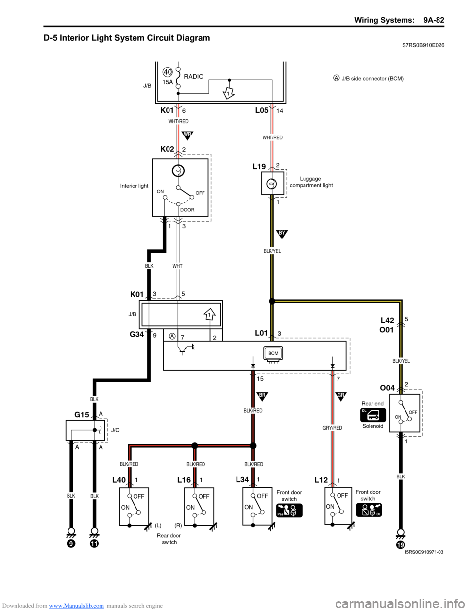
Downloaded from www.Manualslib.com manuals search engine Wiring Systems: 9A-82
D-5 Interior Light System Circuit DiagramS7RS0B910E026
15A
40RADIO
J/B
OFF
DOOR
ON
K02 K012 6
3
1
Interior light
15
7
OFF
ON
OFF
ON
L121
1
GRY/RED
BLK
OFF
ONOFF
ON
L16 L341L401
Rear door
switch Front door
switch
BLK/RED
BLK
BLK
BLK
L0514
WHT/RED
G15
J/C
A
A
5
7G34
K01
J/B
L01
Luggage
compartment light
2
1
3L19
WHT/RED
BLK/YEL
WHT
1119
OFF
ON
O042
L42
O015
1
BLK/YEL
3
Solenoid
2
1
1
J/B side connector (BCM)
A
(L) (R) Front door
switch
A
BLK/REDBLK/REDBLK/RED
Rear end
9
BRGR
9
BLK
A
BY
WR
BCM
I5RS0C910971-03