ppl SUZUKI SWIFT 2006 2.G Service Workshop Manual
[x] Cancel search | Manufacturer: SUZUKI, Model Year: 2006, Model line: SWIFT, Model: SUZUKI SWIFT 2006 2.GPages: 1496, PDF Size: 34.44 MB
Page 1042 of 1496
Downloaded from www.Manualslib.com manuals search engine 8B-4 Air Bag System:
WARNING!
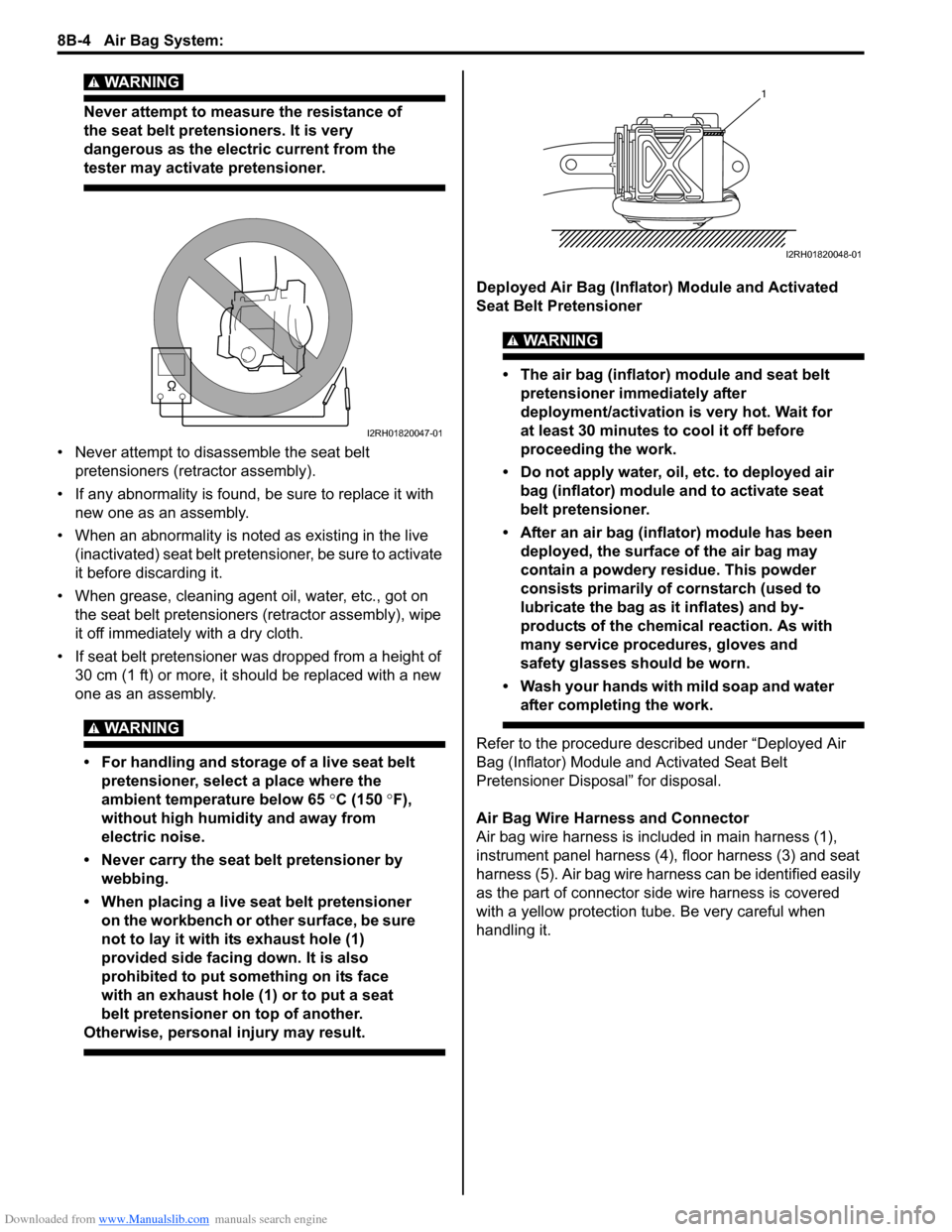
Never attempt to measure the resistance of
the seat belt pretensioners. It is very
dangerous as the electric current from the
tester may activate pretensioner.
• Never attempt to disassemble the seat belt
pretensioners (retractor assembly).
• If any abnormality is found, be sure to replace it with
new one as an assembly.
• When an abnormality is noted as existing in the live (inactivated) seat belt preten sioner, be sure to activate
it before discarding it.
• When grease, cleaning agent oil, water, etc., got on the seat belt pretensioners (r etractor assembly), wipe
it off immediately with a dry cloth.
• If seat belt pretensioner was dropped from a height of 30 cm (1 ft) or more, it should be replaced with a new
one as an assembly.
WARNING!
• For handling and storage of a live seat belt pretensioner, select a place where the
ambient temperature below 65 °C (150 ° F),
without high humidity and away from
electric noise.
• Never carry the seat belt pretensioner by webbing.
• When placing a live seat belt pretensioner on the workbench or other surface, be sure
not to lay it with its exhaust hole (1)
provided side facing down. It is also
prohibited to put something on its face
with an exhaust hole (1) or to put a seat
belt pretensioner on top of another.
Otherwise, personal injury may result.
Deployed Air Bag (Inflator) Module and Activated
Seat Belt Pretensioner
WARNING!
• The air bag (inflator) module and seat belt
pretensioner immediately after
deployment/activation is very hot. Wait for
at least 30 minutes to cool it off before
proceeding the work.
• Do not apply water, oil, etc. to deployed air bag (inflator) module and to activate seat
belt pretensioner.
• After an air bag (inflator) module has been deployed, the surface of the air bag may
contain a powdery residue. This powder
consists primarily of cornstarch (used to
lubricate the bag as it inflates) and by-
products of the chemical reaction. As with
many service procedures, gloves and
safety glasses should be worn.
• Wash your hands with mild soap and water after completing the work.
Refer to the procedure described under “Deployed Air
Bag (Inflator) Module and Activated Seat Belt
Pretensioner Disposal” for disposal.
Air Bag Wire Harness and Connector
Air bag wire harness is includ ed in main harness (1),
instrument panel harness (4), floor harness (3) and seat
harness (5). Air bag wire harness can be identified easily
as the part of connector side wire harness is covered
with a yellow protection tube. Be very careful when
handling it.
I2RH01820047-01
1
I2RH01820048-01
Page 1043 of 1496
Downloaded from www.Manualslib.com manuals search engine Air Bag System: 8B-5
• When an open in air bag wire harness, damaged wire harness, connector or terminal is found, replace wire
harness, connectors and terminals as an assembly.
• When installing it, be careful so that the air bag wire harness is not caught or does not interfere with other
parts.
• Make sure air bag system grounding point (2) is clean and ground is securely fastened for optimum metal-to-
metal contact. Poor grounding can cause intermittent
problems that are difficult to diagnose.Precautions on Disposal of Air Bag and Seat
Belt Pretensioner
S7RS0B8200003
Do not dispose of the live (undeployed) air bag (inflator)
modules and the live (inactivated) seat belt
pretensioners.
When disposal is necessary, be sure to deploy / activate
the air bag and seat belt pretensioner according to
deployment / activation procedure described in “Air Bag
(Inflator) Module and Seat Belt Pretensioner Disposal”.
WARNING!
Failure to follow proper air bag (inflator)
module and seat belt pretensioner disposal
procedures can result in air bag deployment
and pretensioner activation which could
cause personal injury. Undeployed air bag
(inflator) module and inactivated seat belt
pretensioner must not be disposed of
through normal refuse channels.
The undeployed air bag (inflator) module and
inactivated seat belt pretensioner contain
substances that can cause severe illness or
personal injury if the sealed container is
damaged during disposal.
General Description
Air Bag System ConstructionS7RS0B8201001
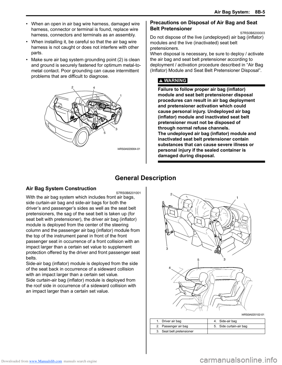
With the air bag system which includes front air bags,
side curtain-air bag and side-air bags for both the
driver’s and passenger’s sides as well as the seat belt
pretensioners, the sag of the s eat belt is taken up (for
seat belt with pretensioner), the driver air bag (inflator)
module is deployed from th e center of the steering
column and the passenger air bag (inflator) module from
the top of the instrument panel in front of the front
passenger seat in occurrence of a front collision with an
impact larger than a certain set value to supplement
protection offered by the driver and front passenger seat
belts.
Side-air bag (inflator) module is deployed from the side
of the seat back in occurrence of a sideward collision
with an impact larger than a certain set value.
Side curtain-air bag (inflator) module is deployed from
the roof side in occurrence of a sideward collision with
an impact larger than a certain set value.
1
2
3
4
5
I4RS0A820004-01
1. Driver air bag 4. Side-air bag
2. Passenger air bag 5. Side curtain-air bag
3. Seat belt pretensioner
I4RS0A820102-01
Page 1045 of 1496
![SUZUKI SWIFT 2006 2.G Service Workshop Manual Downloaded from www.Manualslib.com manuals search engine Air Bag System: 8B-7
Schematic and Routing Diagram
Air Bag System Wiring Circuit DiagramS7RS0B8202001
[A]
[B]“E13” “E44”, “G04� SUZUKI SWIFT 2006 2.G Service Workshop Manual Downloaded from www.Manualslib.com manuals search engine Air Bag System: 8B-7
Schematic and Routing Diagram
Air Bag System Wiring Circuit DiagramS7RS0B8202001
[A]
[B]“E13” “E44”, “G04�](/img/20/7607/w960_7607-1044.png)
Downloaded from www.Manualslib.com manuals search engine Air Bag System: 8B-7
Schematic and Routing Diagram
Air Bag System Wiring Circuit DiagramS7RS0B8202001
[A]
[B]“E13” “E44”, “G04” “G35” and "L03" \
"L41"
1
2 GRN/RED
GRN GRN/RED
GRN
BLU/RED YEL/RED BLU/RED
YEL/RED
GRN/ORN GRN/YEL
RED
13
PPL/WHT
9 7
8
5
6
10 “L10”
“L11”
“L04”
“G35” “G34”
“G33”
“G28”
“G32”
“L35”
L29-2
L29-27
L29-32 L29-5
L29-6 L29-4
L29-3
L29-8
L29-7
IG
ST
YEL L29-37ADS
WHT/RED
LT GRN/BLK L29-46
L29-47 SD+
SD-
11
WHT/GRN LT GRN
BLK L29-45
L29-44 WL
L29-28
E1 DP-
DP+ P- P+ D- D+
“G10”
“G04”“L29”
18
BLU/ORN
BLU/YEL “L36”
L29-9
L29-10
PP-
PP+
19 17
GRY/RED
GRY
L29-12
L29-11
DS- DS+ “L25”
20
BRN/WHT
BRN
L29-13
L29-14
PS- PS+ “L30”
21
YEL/GRN
YEL/BLU
L29-20
L29-19
DC- DC+ “L18”
22
BLK/YEL
BRN/YEL
L29-21
L29-22
PC- PC+ “L41”
2316
15
14
“L29”
SP+
SP-
“G26”“L32”
“L03”“E44”“E13”
12
ORN
PNK/BLK
GRY/RED
GRY L29-50
L29-51 FD+
FD-
3 4
YEL/BLK
YEL/BLK
GRN RED/BLK
I7RS0A820002-03
[A]: Shorting bar
8. BCM 17. Passenger air bag (inflator) module
[B]: Connector 9. To data link connector (DLC)18. Driver seat belt pretensioner
1. To battery 10. Driver side-sensor (if equipped)19. Passenger seat belt pretensioner
2. Ignition switch 11. Passenger side-sensor (if equipped) 20. Driver side-air bag (inflator) module (if equipped)
3. “AIR BAG” warning light 12. Forward-sensor 21. Passenger side-air bag (inflator) module (if equipped)
4. Light driver 13. Ground for air bag system 22. Driver side curtain-air bag (inflator) module (if equipped)
5. “METER” fuse 14. SDM 23. Passenger side curtain-air bag (inflator) module (if equipped)
6. “A/BAG” fuse 15. Contact coil
7. Junction block assembly 16. Driver air bag (inflator) module
Page 1051 of 1496
Downloaded from www.Manualslib.com manuals search engine Air Bag System: 8B-13
Scan Tool DataS7RS0B8204006
Data list of SDM
Definition
Back Up Volt (V)
This parameter indicates the capacity of the backup
condenser installed to maintain the ignition current (as
much as possible) even when the power supply to SDM
that ignites the inflator is shut off.
Battery Voltage (V)
Battery voltage is an analog input signal read by SDM.
System ID (4ch/8ch)
This parameter indicates the number of initiator circuits.
Driv A/B Ini Res (Driver air bag initiator resistance)
(ohm)
This parameter indicates the resistance of the driver air
bag initiator circuit. Pass A/B Ini Res (Passenger air bag initiator
resistance) (ohm)
This parameter indicates the
resistance of the passenger
air bag initiator circuit.
Driv Preten Ini Res (Dri ver pretensioner initiator
resistance) (ohm)
This parameter indicates the resistance of the driver seat
belt pretensioner initiator circuit.
Pass Preten Ini Res (Passenger pretensioner
initiator resistance) (ohm)
This parameter indicates the resistance of the passenger
seat belt pretensioner initiator circuit.
Driv Sidebag Ini Res (Driver side-air bag initiator
resistance) (ohm)
This parameter indicates the resistance of the driver
side-air bag initiator circuit.
Pass Sidebag Ini Res (Passenger side-air bag
initiator resistance) (ohm)
This parameter indicates the resistance of the
Passenger side-air bag initiator circuit.
Driv curtain Ini Res (Driver side curtain-air bag
initiator resistance) (ohm)
This parameter indicates the re sistance of the driver side
curtain-air bag initiator circuit.
Pass curtain Ini Res (Passenger side curtain-air bag
initiator resistance) (ohm)
This parameter indicates the resistance of the passenger
side curtain-air bag initiator circuit.
“AIR BAG” Warning Right Comes ON SteadyS7RS0B8204007
Wiring Diagram Normal Condition /
Reference Value
�) Battery voltage 10 – 14 V
�) Back up volt 27.0 – 33.0 V
�) System ID 4ch or 8ch
�) Driv A/B Ini Res 2.1 – 3.8 ohm
�) Pass A/B Ini Res 1.8 – 2.8 ohm
�) Driv Preten Ini Res 1.8 – 2.9 ohm
�) Pass Preten Ini Res 1.8 – 2.9 ohm
�) Driv Sidebag Ini Res 1.8 – 2.6 ohm
�) Pass Sidebag Ini Res 1.8 – 2.6 ohm
�) Driv curtain Ini Res 1.8 – 2.8 ohm
�) Pass curtain Ini Res 1.8 – 2.8 ohm
1
2 GRN
11
BLK
L29-27
L29-2
L29-28 WL
E1
IG
L29-32
ST
10
8
“L29”
RED
PPL/WHT
7
3
4 “L04”
“G34”
“G33”
“G28”
“G32”
5 6
“G32”
YEL/BLK
YEL/BLK
RED/BLK
9
I7RS0B820002-02
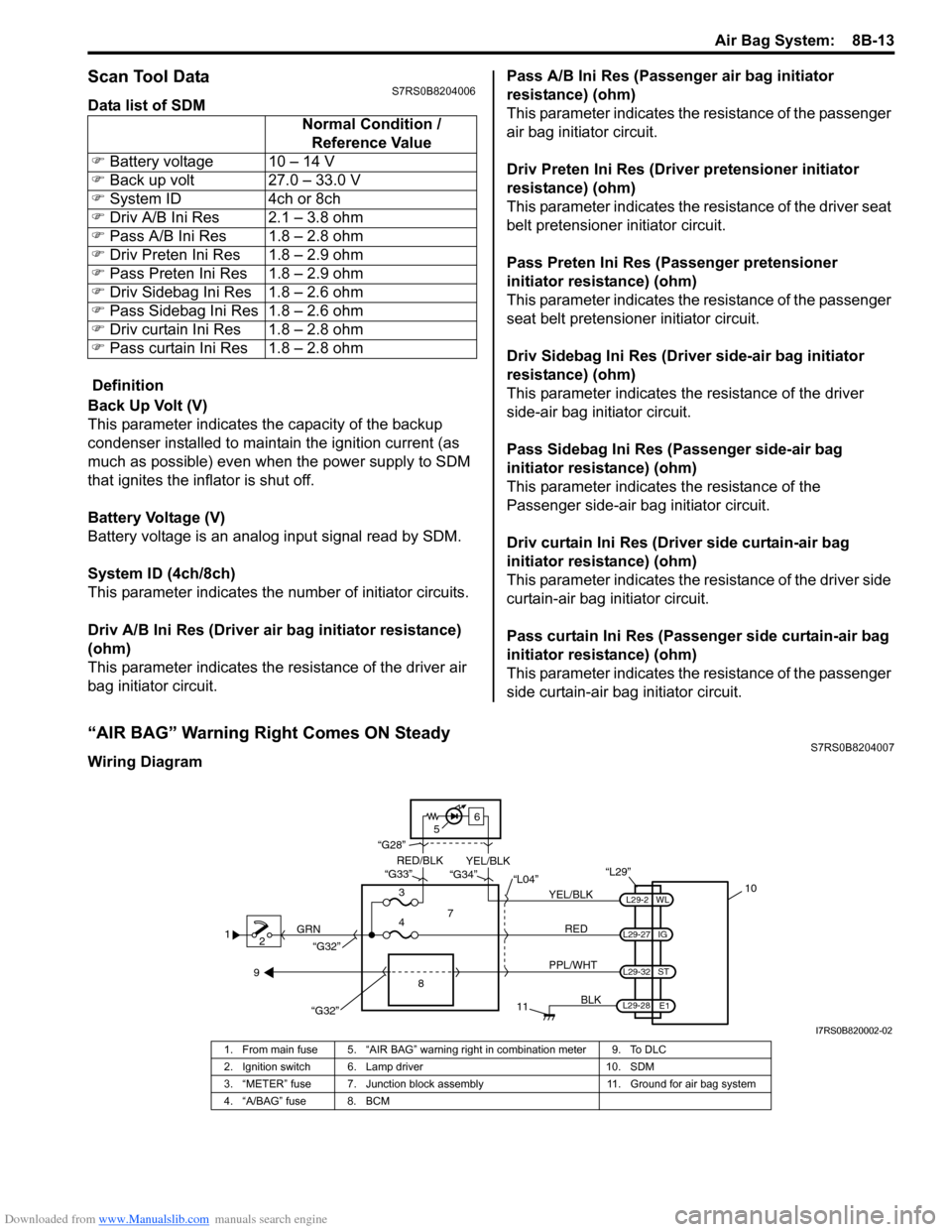
1. From main fuse 5. “AIR BAG” warning right in combination meter 9. To DLC
2. Ignition switch 6. Lamp driver 10. SDM
3. “METER” fuse 7. Junction block assembly 11. Ground for air bag system
4. “A/BAG” fuse 8. BCM
Page 1052 of 1496
Downloaded from www.Manualslib.com manuals search engine 8B-14 Air Bag System:
CAUTION!
• Be sure to perform “Air Bag Diagnostic System Check” before starting diagnosis according to flow.
• When measurement of resistance or voltage is required in this flow, use a tester along with a correct terminal adapter from special tool (Connector test adapter kit).
• When a check for proper connection is required, refer to “Inspection of Intermittent and Poor Connections”.
• If there is open circuit in the air bag wire harnes s, connector or terminal is found damaged, replace
the wire harness, connector and terminal as an assembly.
Flow Test Description
Step 1: Check for “A/BAG” fuse blown.
Step 2, 3: Check for loose connection between junction block assembly connector and junction block
assembly.
Step 4: Check for loose connection between SDM connector and SDM.
Step 5: Check for SDM power supply circuit.
Step 6: Check for short circuit between “A IR BAG” warning right circuit and ground.
Troubleshooting Step Action YesNo
1 1) Turn ignition switch OFF.
2) Remove and inspect “A/BAG” fuse.
Is fuse good? Go to Step 2.
“RED” wire short to
ground.
After repair, replace “A/
BAG” fuse.
2 1) Check for loose connection of junction block assembly connector “L04”.
Is it connected securely? Go to Step 3.
Correct connector “L04”
securely.
3 1) Check for loose connection of junction block assembly connector “G34”.
Is it connected securely? Go to Step 4.
Correct connector “G34”
securely.
4 1) Check for loose connection of SDM connector “L29”. Is it connected securely? Go to Step 5.
Correct connector “L29”
securely.
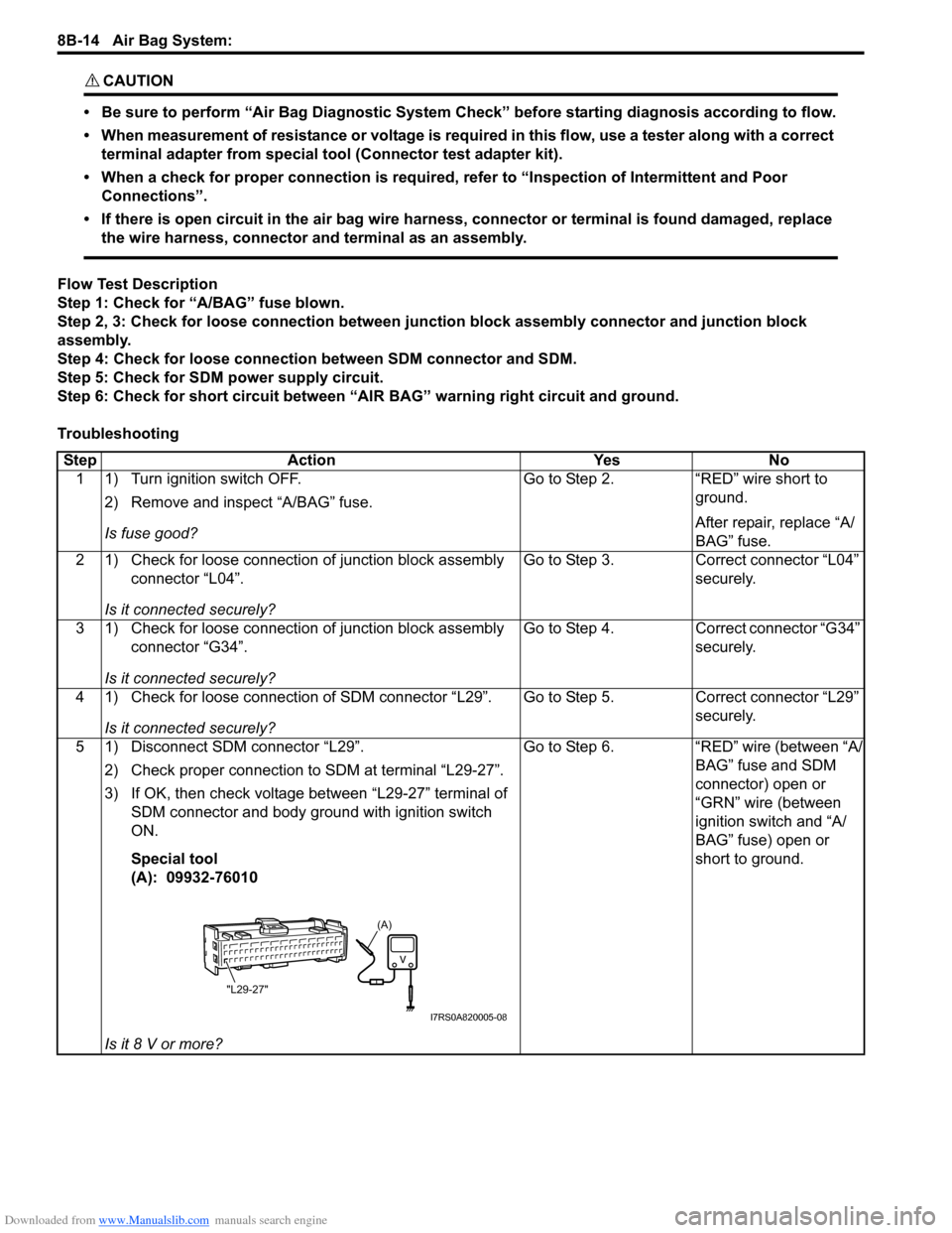
5 1) Disconnect SDM connector “L29”. 2) Check proper connection to SDM at terminal “L29-27”.
3) If OK, then check voltage between “L29-27” terminal of SDM connector and body ground with ignition switch
ON.
Special tool
(A): 09932-76010
Is it 8 V or more? Go to Step 6.
“RED” wire (between “A/
BAG” fuse and SDM
connector) open or
“GRN” wire (between
ignition switch and “A/
BAG” fuse) open or
short to ground.
(A)
"L29-27"
I7RS0A820005-08
Page 1053 of 1496
Downloaded from www.Manualslib.com manuals search engine Air Bag System: 8B-15
NOTE
Upon completion of inspection and repair work, perform the following items.
• Reconnect all air bag system components and ensure all components are properly mounted.
• Repeat “Air Bag Diagnostic System Check” to confirm that the trouble has been corrected.
“AIR BAG” Warning Right Does Not Come ONS7RS0B8204008
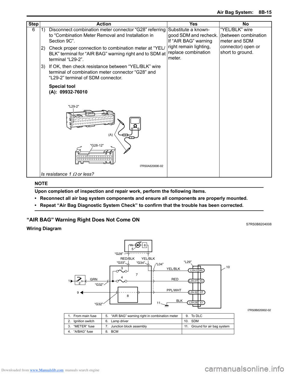
Wiring Diagram6 1) Disconnect combination meter connector “G28” referring
to “Combination Meter Removal and Installation in
Section 9C”.
2) Check proper connection to combination meter at “YEL/ BLK” terminal for “AIR BAG” warning right and to SDM at
terminal “L29-2”.
3) If OK, then check resistance between “YEL/BLK” wire terminal of combination meter connector “G28” and
“L29-2” terminal of SDM connector.
Special tool
(A): 09932-76010
Is resistance 1
Ω or less? Substitute a known-
good SDM and recheck.
If “AIR BAG” warning
right remain lighting,
replace combination
meter.
“YEL/BLK” wire
(between combination
meter and SDM
connector) open or
short to ground.
Step Action Yes No
"L29-2"
"G28-12"
(A)
I7RS0A820006-02
12 GRN
11
BLK
L29-27
L29-2
L29-28 WL
E1
IG
L29-32
ST
10
8
“L29”
RED
PPL/WHT
7
3
4 “L04”
“G34”
“G33”
“G28”
“G32”
5 6
“G32”
YEL/BLK
YEL/BLK
RED/BLK
9
I7RS0B820002-02
1. From main fuse 5. “AIR BAG” warning right in combination meter 9. To DLC
2. Ignition switch 6. Lamp driver 10. SDM
3. “METER” fuse 7. Junction block assembly 11. Ground for air bag system
4. “A/BAG” fuse 8. BCM
Page 1054 of 1496
Downloaded from www.Manualslib.com manuals search engine 8B-16 Air Bag System:
CAUTION!
• Be sure to perform “Air Bag Diagnostic System Check” before starting diagnosis according to flow.
• When measurement of resistance or voltage is required in this flow, use a tester along with a correct terminal adapter from special tool (Connector test adapter kit).
• When a check for proper connection is required, refer to “Inspection of Intermittent and Poor Connections”.
• If there is open circuit in the air bag wire harnes s, connector or terminal is found damaged, replace
the wire harness, connector and terminal as an assembly.
Flow Test Description
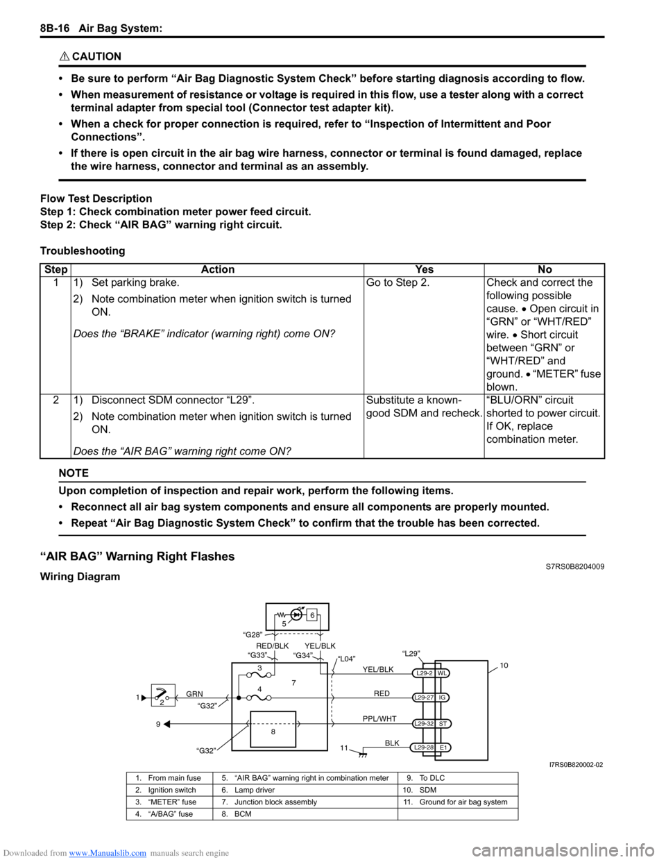
Step 1: Check combination meter power feed circuit.
Step 2: Check “AIR BAG” warning right circuit.
Troubleshooting
NOTE
Upon completion of inspection and repair work, perform the following items.
• Reconnect all air bag system components and ensure all components are properly mounted.
• Repeat “Air Bag Diagnostic System Check” to confirm that the trouble has been corrected.
“AIR BAG” Warning Right FlashesS7RS0B8204009
Wiring Diagram Step Action Yes No
1 1) Set parking brake.
2) Note combination me ter when ignition switch is turned
ON.
Does the “BRAKE” in dicator (warning right) come ON? Go to Step 2. Check and correct the
following possible
cause. • Open circuit in
“GRN” or “WHT/RED”
wire. • Short circuit
between “GRN” or
“WHT/RED” and
ground. • “METER” fuse
blown.
2 1) Disconnect SDM connector “L29”.
2) Note combination me ter when ignition switch is turned
ON.
Does the “AIR BAG” warning right come ON? Substitute a known-
good SDM and recheck.
“BLU/ORN” circuit
shorted to power circuit.
If OK, replace
combination meter.
1
2 GRN
11
BLK
L29-27
L29-2
L29-28 WL
E1
IG
L29-32
ST
10
8
“L29”
RED
PPL/WHT
7
3
4 “L04”
“G34”
“G33”
“G28”
“G32”
5 6
“G32”
YEL/BLK
YEL/BLK
RED/BLK
9
I7RS0B820002-02
1. From main fuse 5. “AIR BAG” warning right in combination meter 9. To DLC
2. Ignition switch 6. Lamp driver 10. SDM
3. “METER” fuse 7. Junction block assembly 11. Ground for air bag system
4. “A/BAG” fuse 8. BCM
Page 1057 of 1496
Downloaded from www.Manualslib.com manuals search engine Air Bag System: 8B-19
CAUTION!
• Be sure to perform “Air Bag Diagnostic System Check” before starting diagnosis according to flow.
• When measurement of resistance or voltage is required in this flow, use a tester along with a correct terminal adapter from special tool (Connector test adapter kit).
• When a check for proper connection is required, refer to “Inspection of Intermittent and Poor Connections”.
• If there is open circuit in the air bag wire harnes s, connector or terminal is found damaged, replace
the wire harness, connector and terminal as an assembly.
DTC Will Set when
The power source voltage to SDM is above an approx. 21 V for specified time.
Flow Test Description
Step 1: Check if voltage applie d to SDM is within normal range.
Step 2: Check if DTC B1016 still exists.
DTC Troubleshooting
NOTE
Upon completion of inspection and repair work, perform the following items.
• Reconnect all air bag system components and ensure all components are properly mounted.
• Clear DTCs referring to “DTC Clearance”, if any.
• Repeat “Air Bag Diagnostic System Check” to confirm that the trouble has been corrected.
Step Action YesNo
1 1) With ignition switch OFF, disconnect SDM connector.
2) Check proper connection to SDM at “L29-27” terminal.
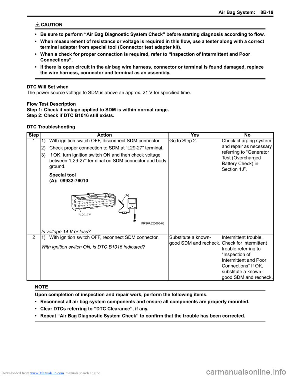
3) If OK, turn ignition switch ON and then check voltage between “L29-27” terminal on SDM connector and body
ground.
Special tool
(A): 09932-76010
Is voltage 14 V or less? Go to Step 2.
Check charging system
and repair as necessary
referring to “Generator
Test (Overcharged
Battery Check) in
Section 1J”.
2 1) With ignition switch OFF, reconnect SDM connector. With ignition switch ON , is DTC B1016 indicated? Substitute a known-
good SDM and recheck.
Intermittent trouble.
Check for intermittent
trouble referring to
“Inspection of
Intermittent and Poor
Connections” If OK,
substitute a known-
good SDM and recheck.
(A)
"L29-27"
I7RS0A820005-08
Page 1058 of 1496
Downloaded from www.Manualslib.com manuals search engine 8B-20 Air Bag System:
DTC B1017: Power Source Voltage LowS7RS0B8204013
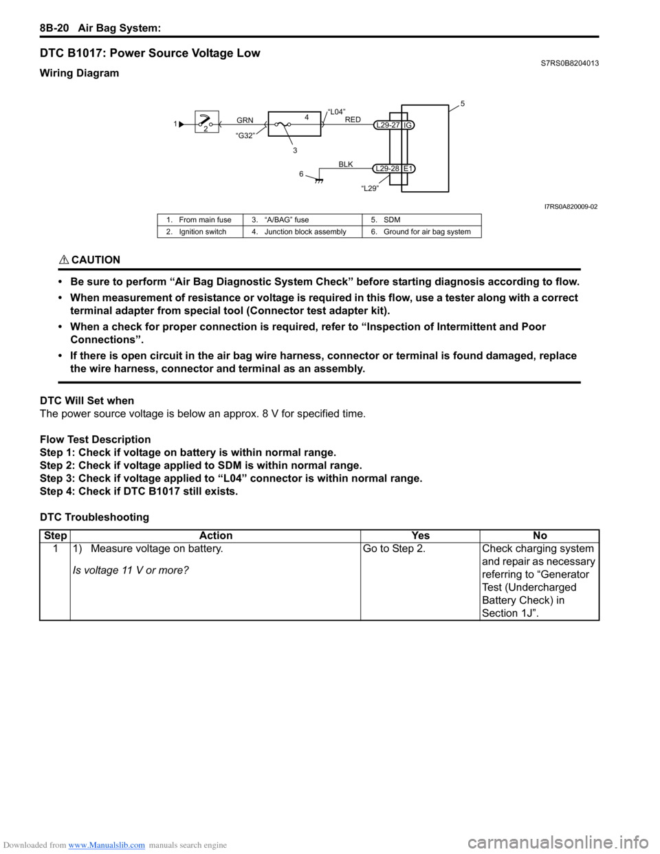
Wiring Diagram
CAUTION!
• Be sure to perform “Air Bag Diagnostic System Check” before starting diagnosis according to flow.
• When measurement of resistance or voltage is required in this flow, use a tester along with a correct terminal adapter from special tool (Connector test adapter kit).
• When a check for proper connection is required, refer to “Inspection of Intermittent and Poor Connections”.
• If there is open circuit in the air bag wire harnes s, connector or terminal is found damaged, replace
the wire harness, connector and terminal as an assembly.
DTC Will Set when
The power source voltage is below an approx. 8 V for specified time.
Flow Test Description
Step 1: Check if voltage on ba ttery is within normal range.
Step 2: Check if voltage applie d to SDM is within normal range.
Step 3: Check if voltage applied to “L04” connector is within normal range.
Step 4: Check if DTC B1017 still exists.
DTC Troubleshooting
1 2
3
GRN
RED
6
BLK
L29-27
L29-28 IG
E1 5
4
“L29”
“L04”
“G32”
I7RS0A820009-02
1. From main fuse 3. “A/BAG” fuse 5. SDM
2. Ignition switch 4. Junction block assembly 6. Ground for air bag system
Step Action YesNo
1 1) Measure voltage on battery.
Is voltage 11 V or more? Go to Step 2.
Check charging system
and repair as necessary
referring to “Generator
Test (Undercharged
Battery Check) in
Section 1J”.
Page 1079 of 1496
Downloaded from www.Manualslib.com manuals search engine Air Bag System: 8B-41
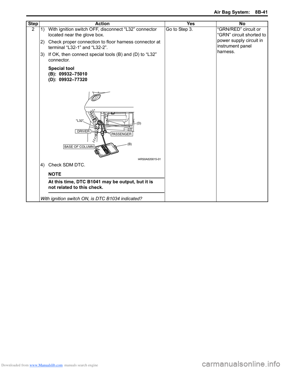
2 1) With ignition switch OFF, disconnect “L32” connector located near the glove box.
2) Check proper connection to floor harness connector at terminal “L32-1” and “L32-2”.
3) If OK, then connect special tools (B) and (D) to “L32” connector.
Special tool
(B): 09932–75010
(D): 09932–77320
4) Check SDM DTC.
NOTE
At this time, DTC B1041 ma y be output, but it is
not related to this check.
With ignition switch ON , is DTC B1034 indicated? Go to Step 3. “GRN/RED” circuit or
“GRN” circuit shorted to
power supply circuit in
instrument panel
harness.
Step Action Yes No
(B) (D)
"L32"BASE OF COLUMN
DRIVERPASSENGER
I4RS0A820015-01