ppl SUZUKI SWIFT 2006 2.G Service Workshop Manual
[x] Cancel search | Manufacturer: SUZUKI, Model Year: 2006, Model line: SWIFT, Model: SUZUKI SWIFT 2006 2.GPages: 1496, PDF Size: 34.44 MB
Page 1204 of 1496
Downloaded from www.Manualslib.com manuals search engine 9A-33 Wiring Systems:
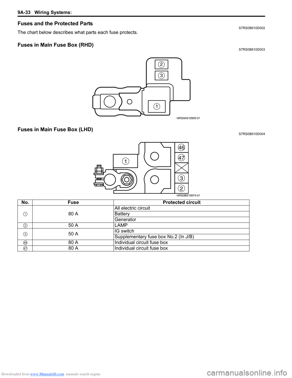
Fuses and the Protected PartsS7RS0B910D002
The chart below describes what parts each fuse protects.
Fuses in Main Fuse Box (RHD)S7RS0B910D003
Fuses in Main Fuse Box (LHD)S7RS0B910D004
No.Fuse Protected circuit
80 A All electric circuit
Battery
Generator
50 A LAMP
50 A IG switch
Supplementary fuse box No.2 (In J/B)
80 A Individual circuit fuse box
80 A Individual circuit fuse box
1
3
2
I4RS0A910905-01
2
3
47
46
1
I4RS0B910974-01
Page 1223 of 1496
Downloaded from www.Manualslib.com manuals search engine Wiring Systems: 9A-52
"E-1"
"E-2"
EGR
stepper motor
PPL
P
"A-6"
AB
AB
CD
CD
ECM
2
3
REDORNGRY/RED
EVAP
thermistor
1
2G09
13
ORN
ORN
E38
G36
BW
Blower
speed
selector
Auto
unit
A/C refrigerant
pressure sensor
E04
C10
BRN/YEL
WHT/REDGRN/RED
6
4312
5
CKP
sensor CMP
sensor VSS
TCM
C37
BLK
3
155830
C25
21
3CDE12CDE23 3
1
CDE31
1 2
3
C08
C20
C37
18 19
4320
219
PNK
RED/YEL
E2354
55
C36
E2410
1
2
3
19
4
RED/WHT
49
BLK/RED
BLK
C012
1 3
IAC
valve
BLU/WHT
GRN/ORN
WHT/BLK
57
4
WHT/BLK
BLK/RED
BLK/ORNBLK/ORNBLK/ORNBLK/ORN
C40Weld splice
BLK/ORNBLK/ORN
C38Weld splice
BLK/REDBLK/RED
BLK/REDBLK/RED
M13A engine M/T, M15A engine M/T
A/T
M13A engine
M15A engine
M16A engine
ABCDE
Manual A/C
Auto A/C
I7RS0B910941-01
Page 1224 of 1496
Downloaded from www.Manualslib.com manuals search engine 9A-53 Wiring Systems:
J/C
E43
J/C
G16
DLC
G20
G375
E469
E38
G3614
C36 E2415
BLK/ORN
BLK/ORN
BLK/ORN
4
BLK
11
J/C
G15
5
4
516
WHT/RED
C37
GRN/YELGRN/WHT
5 6
YG
BRN
B
P/S
Cont.M
4
"F-3"
25
A
A D
E
AA
PPL/WHT
PPL/WHT
PPL/WHT
PPL/WHT
YEL/GRNWHT/RED
BLK
9
A
PPL
E42
PPLJ/C
ECM
E394
J/B15A RADIO
40
E23
E23
YEL/BLKYEL/REDRED/BLU
13
282620
BLK
2C37
M/T
A/T
48
W
WHT
30
GYGW
BRN/WHTBLU/YEL
28
8
BWBY
IG COIL
#1 Generator
IG COIL
#2
(CAN) "A-3""A-2"
Audio
"G-1"
GRN/WHT
P
7
BCM
Starting motor relay
"A-1"
Transaxle
range sensor
YG"A-1"
ICM
"A-7"
P/S
Cont.M
"F-3"YBYRRBGW"D-7"
Brake light switch
"A-1"Starting motor
PW
PW
G335
WHT/BLKRED/BLK
RBWB
"A-8"
14
6
BCM
A
J/C
E43
APPL
P
E42C
IF EQPD IF EQPD
IF EQPD
I6RS0C910913-03
Page 1226 of 1496
Downloaded from www.Manualslib.com manuals search engine 9A-55 Wiring Systems:
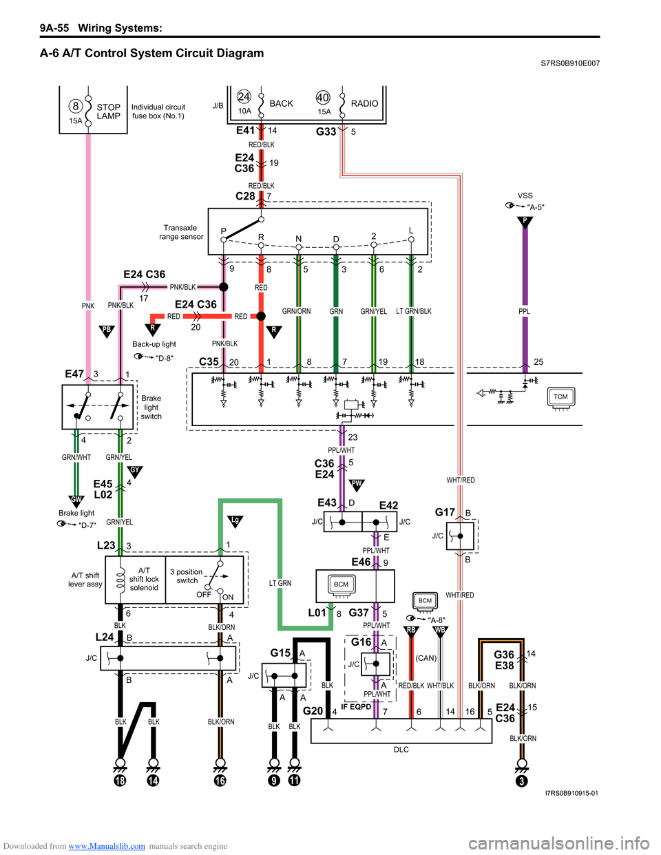
A-6 A/T Control System Circuit DiagramS7RS0B910E007
GRN/YEL
Brakelight
switch
E47
GRN/YEL
C3520 8 7 19 18
9
85 3 6 2
GRN/YEL
Back-up light
20
RED
"D-8"
R
Transaxle
range sensor
TCM
L23
4
3 position switch
A/T
shift lock solenoid
A/T shift
lever assy
BLK/ORN
16
OFF ON
RED
1
RED
BLK
PNK/BLK
GRN/ORNLT GRN/BLK
C28
P
R ND 2L
PNK/BLK
1
2
E24 C36
17
PNK/BLK
BLK
63
BLK/ORN
18
BLK
14
L24
J/C
E45
L024
J/C
E43
J/C (CAN)
G16
BCM
DLC
G207
G375
E469
4
BLK
BLKBLK
11
J/C
G15
3
G36
E3814
E24
C3615
BLK/ORNBLK/ORN
5
23
GRN
RED/BLK
7
E24
C3619
E4114
RED/BLK
PNK
15A
STOP
LAMP8
GRN/WHT
GW
"D-7"
Brake light
3
4
J/B
L018
1
24
10ABACK
A
A
B
B A
A
PPL/WHT
PPL/WHT
PPL/WHT
PPL/WHT
A
A
D
E
LT GRN
P
"A-5"
VSS
PPL
25
R
C36E245
Lg
GY
PB
PW
9
A
Individual circuit
fuse box (No.1)
WHT/BLKRED/BLK
RBWB
BCM
"A-8"
14
6
BLK/ORN
15ARADIO40
G335
WHT/RED
B
B
J/C
G17
WHT/RED
16
J/C
E42
IF EQPD
E24 C36
I7RS0B910915-01
Page 1228 of 1496
Downloaded from www.Manualslib.com manuals search engine 9A-57 Wiring Systems:
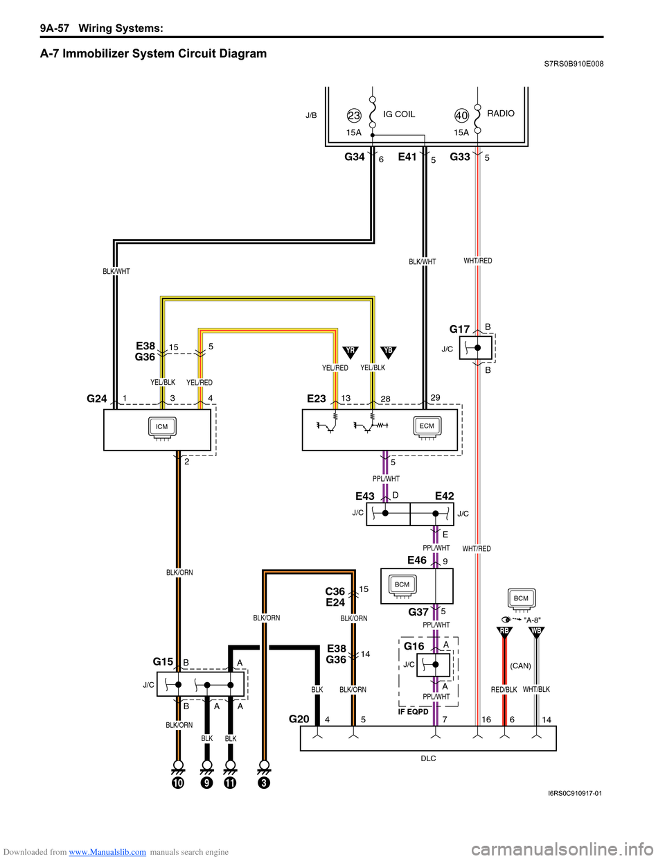
A-7 Immobilizer System Circuit DiagramS7RS0B910E008
ECMICM
DLC
G204
10
J/C
G15
5
5
7
113
IG COIL
G346
J/B
29
15A
23
BLK/WHT
13 28
YEL/BLK
YBYR
E38
G3614
C36 E2415
BLK/ORN
BLK/ORN
BLK/ORN
BLK
J/C
E43
J/C
G16
BCM
G375
E469
16
WHT/RED
E233G241 4
BLK/ORN
2
E38
G36515
G335
15A RADIO
40
E415
YEL/REDYEL/BLK
WHT/REDBLK/WHT
J/C
G17
PPL/WHT
PPL/WHT
PPL/WHT
D
E
PPL/WHT
A
A B
B
A A
B
B
YEL/RED
9
A
BLK/ORN
BLKBLK
WHT/BLKRED/BLK
RBWB"A-8"
14
6
BCM
E42
J/C
IF EQPD (CAN)
I6RS0C910917-01
Page 1229 of 1496
Downloaded from www.Manualslib.com manuals search engine Wiring Systems: 9A-58
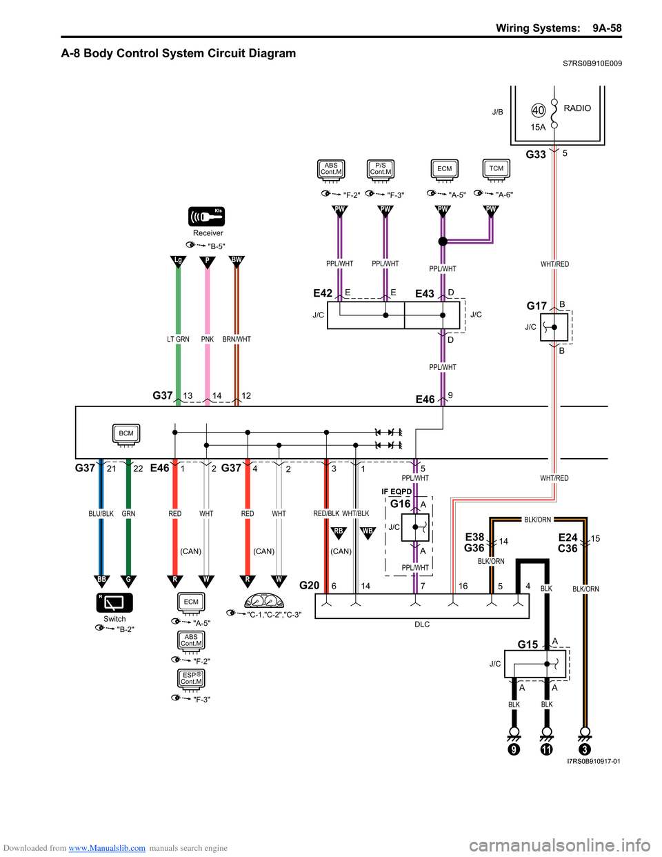
A-8 Body Control System Circuit DiagramS7RS0B910E009
1E462
WHTRED
4G372
WHTRED
3
G20
1
6 14
WHT/BLKRED/BLK
PNKLT GRN
G37
DLC
4
11
BLK
BLK
A
A
J/C
G15
13 1412
Receiver
5PPL/WHTWHT/RED
PPL/WHT
A
A
J/C
G16
"A-5""F-2""F-3"
9E46
PPL/WHT
ECM
E
D
J/C
EDE43
PPL/WHTPPL/WHT
P/S
Cont.MABS
Cont.M
E42
RW
PW
PPL/WHT
PWPWPW
"A-6"
TCM
E38
G3614E24
C3615
BLK/ORN
5
3
J/B
15A RADIO
40
G335
WHT/RED
BLK/ORN
716
B
B
J/C
G17
BLK/ORN
"C-1,"C-2","C-3"
"B-2"
Switch
21G3722
GRNBLU/BLK
BBG
BWPLg
"B-5"
RW
"A-5"
J/C
9
BLK
A
RBWB
ECM
"F-2"
ABS
Cont.M
"F-3"
ESP
Cont.M
BCM
BRN/WHT
IF EQPD
(CAN) (CAN) (CAN)
R
I7RS0B910917-01
Page 1232 of 1496
Downloaded from www.Manualslib.com manuals search engine 9A-61 Wiring Systems:
50A
3
J/B
15ARADIO
40
2
15A
ACC 1
26
10
1
20AD/L
34
11
10A
METER
25
Main fuse box
WHT
E402
20
Blower motor relay
"Junction Block Inner circuit"
Relay
J/B (BCM- 20 )J/B (BCM- 17 )
17
2L04
9
3
83
B BG33
3
4L05
10
J/C
G15
BLK/ORN
BLK/ORN
16
BLK/ORN
"F-1"
YELPPL/WHT
A/B
SDM
14
316E417G34
Front
position light
"D-2"
"D-2, D-4, G-1"
J/B
RED/YELRED/YEL
J/C
L74D
DD
Licence plate light
"D-2"
YPW
"A-2"
Generator
E464
WHT/BLU
WB
RYRY
RYRYRY
Tail light
(R)
Tail light
(L)
"D-2"
RED/YEL
RED/YEL
RED/YEL
811
C CG37
J/C
G16
YEL
GRYYEL
GY
C
YEL
Y
"G-2"
Multi information
display Auto
unit
"E-2"
A
A
J/C
2E26
+B1
LOCK
ACC
ON
ST ACC IG1 IG2
STOUT
IN
+B2
BLUGRN
G3252
56G21
J/B side connector (BCM)
A
BCM
I7RS0B910919-01
Page 1243 of 1496
Downloaded from www.Manualslib.com manuals search engine Wiring Systems: 9A-72
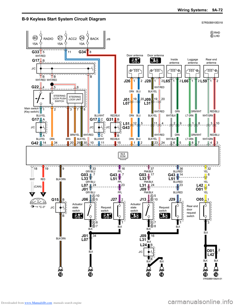
B-9 Keyless Start System Circuit DiagramS7RS0B910E018
BLKBLK
BLK
BLKBLK
YELBLU/REDPNK/BLKPPLGRY/BLU
YELBLU/REDPNK/BLKPPLGRY/BLU
YELBLU/REDPNK/BLKPPLGRY/BLU
G33
KLS
ECM
WHT/RED
WHT/REDWHT/RED
BLU/YEL
WHTRED
ORN
BLU/YEL
"C-3"
WR
G42143420
1819
BLK/ORN
BLK/ORN
9
5
J/B
15A RADIO
40
G348
10A
BACK
24
11
15A
ACC2
27
B
B
B
J/C
G17
B
A
A
J/C
BLU/WHT
BLU/WHT
C
C
J/C
G17
Main switch
(Key switch)
STEERING
LOCK PUSH SWITCH
G22456
1
O051
3
2
BRN29
BRN/YEL
301011RED/BLK
RED/BLK
B
B
J/C
Rear end
door
request
switch
G31
15ORN
ORN
ORN
1BLK/YEL
WHT/RED
378
STEERING
LOCK UNIT
Door antenna
L51
G4312
J01
L07 J261912
BLU
BLU
BLU
2
5
20
WHT/BLK
WHT/BLK6
Inside
antenna
2
12
GRN
GRN
5
9
LT GRN
LT GRN8
Luggage antenna
1
12
GRN/WHT
GRN/WHT
7
8
BLK/YEL
BLK/YEL
BLK/YEL
23
Door antenna
11
J09
L31 J28 L65 L66
WHT/GRN
WHT/GRN4
Rear end
antenna
3
12
RED/BLU
RED/BLU
3
10
L59
1912
WHT/RED
WHT/RED
WHT/RED
24
4
20
G17
B
B
J/C
G15
10
BLK
BLKBLK
32
J292
1
Request
switch
36
1914
J13
Actuator
state
switch
O01 L422
16
BLK
37
1814
J09
L31
J272
1
Request
switch
16
J06
Actuator
state
switch
34
BLK
BLK
33
18
J01
L07
(CAN) RHD
A
LHD
B
AB10
5AB5
10
AB8
7AB7
8
614G43
L5117G03 L337G43 L517G03 L33
423242324L42
O01
L31
J09
L07
J01
B
J/C
B
L24
I7RS0B910924-01
Page 1262 of 1496
Downloaded from www.Manualslib.com manuals search engine 9A-91 Wiring Systems:
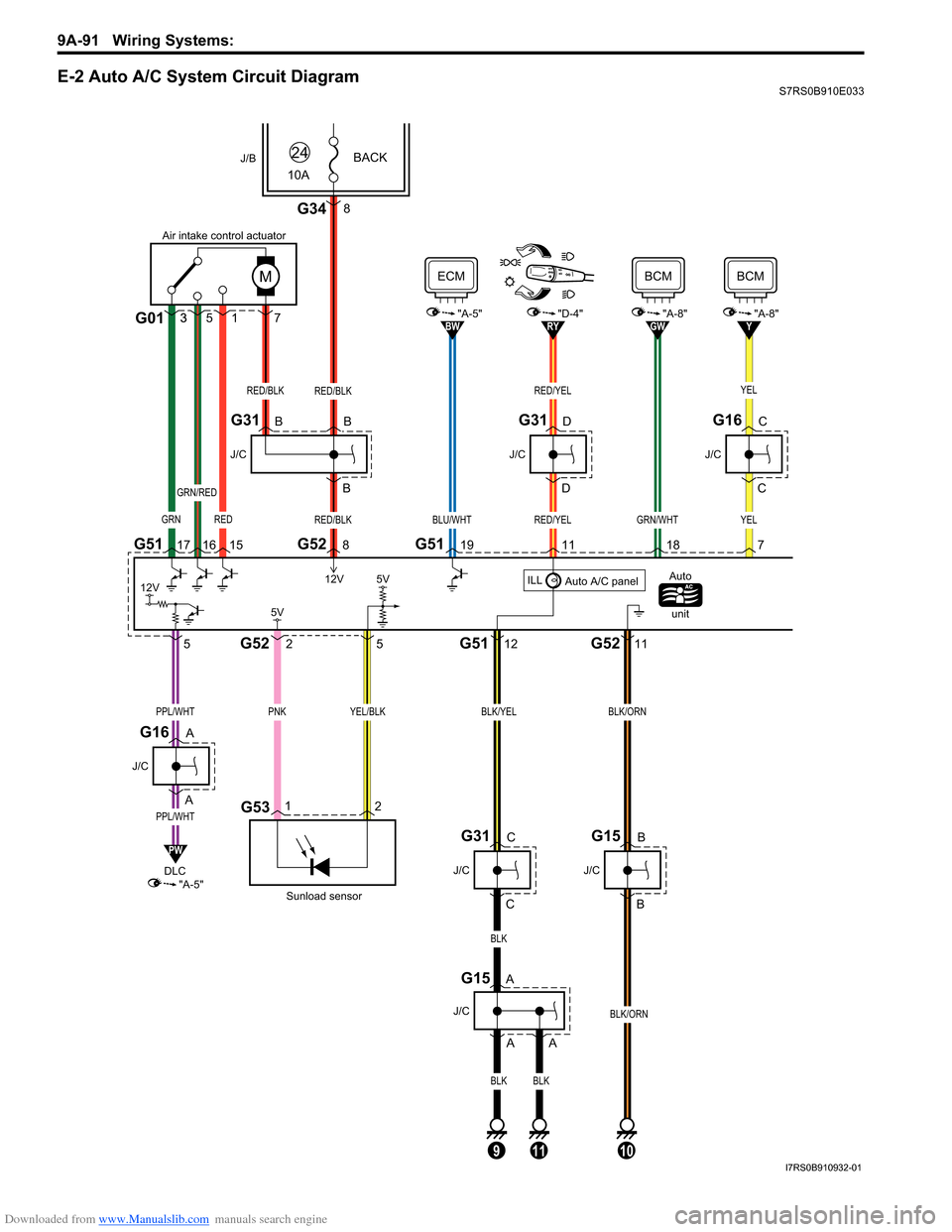
E-2 Auto A/C System Circuit DiagramS7RS0B910E033
12G53
G51
G52
G51
G52 G52 G51
251211
11
15
17
12V
198
REDGRN
RED/BLK
GRN/RED
RED/YEL
RED/YELRED/BLK
RED/BLKBLU/WHT
M
7133G01
8G34
ILL
Auto A/C panel
Sunload sensor
DLC Auto
unit
Air intake control actuator
BACK
10A24
"A-5"
PW
"A-5"BW"D-4"RY
18
GRN/WHT
"A-8"GW
ECMBCMBCM
BLK/ORN
YEL/BLKPNK
5
PPL/WHT
PPL/WHT
BLK/ORNBLK/YEL
5V 5V
12V
J/B
7
YEL
YEL
"A-8"Y
109
G31
J/C
D
D
G15
J/C
B
B
BLK
BLK
G31
J/C
C
C
G16
J/C
C
C
G15
J/C
A A
11
BLK
A
G16
J/C
A
A
J/C
BG31B B
16
5
I7RS0B910932-01
Page 1264 of 1496
Downloaded from www.Manualslib.com manuals search engine 9A-93 Wiring Systems:
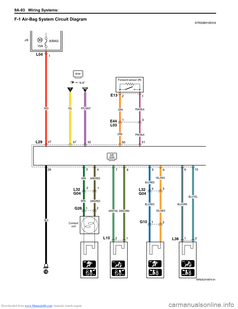
F-1 Air-Bag System Circuit DiagramS7RS0B910E034
3
ORN
YPW
A/B
SDM
L29
J/B
15A A/BAG
30
RED
L04
BCM
15
BLK
1
E44
L031
PNK/BLK
E13
Forward sensor (R)
1
2
Contact
coil
G2612
L32
G0421
L1021
YEL/RED
GRN/RED
G101 2
43
YEL/RED
L3612
3
4 7
856910
28 27
37 32 5051
"A-8"
L32
G04
ORN
PNK/BLKYELPPL/WHT
GRN
GRNGRN/RED
GRN/YELGRN/ORN
BLU/RED
BLU/REDBLU/ORN
BLU/YEL
I5RS0C910974-01