ron SUZUKI SWIFT 2006 2.G Service Workshop Manual
[x] Cancel search | Manufacturer: SUZUKI, Model Year: 2006, Model line: SWIFT, Model: SUZUKI SWIFT 2006 2.GPages: 1496, PDF Size: 34.44 MB
Page 1374 of 1496
Downloaded from www.Manualslib.com manuals search engine 9J-5 Hood / Fenders / Doors:
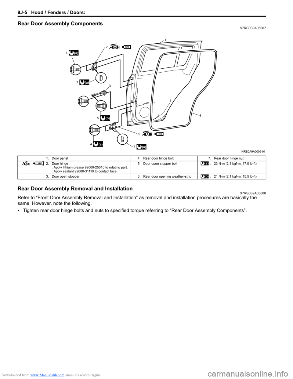
Rear Door Assembly ComponentsS7RS0B9A06007
Rear Door Assembly Removal and InstallationS7RS0B9A06008
Refer to “Front Door Assembly Removal and Installation” as removal and installation procedures are basically the
same. However, note the following.
• Tighten rear door hinge bolts and nuts to specified torque referring to “Rear Door Assembly Components”.
2
2
(a)4
(a)4
(a)7
(a)7
(b)53
6
1
I4RS0A9A0009-01
1. Door panel 4. Rear door hinge bolt7. Rear door hinge nut
2. Door hinge : Apply lithium grease 99000-25010 to rotating part.
: Apply sealant 99000-31110 to contact face. 5. Door open stopper bolt
: 23 N⋅m (2.3 kgf-m, 17.0 lb-ft)
3. Door open stopper 6. Rear door opening weather-strip: 21 N⋅m (2.1 kgf-m, 15.5 lb-ft)
Page 1377 of 1496
Downloaded from www.Manualslib.com manuals search engine Hood / Fenders / Doors: 9J-8
Specifications
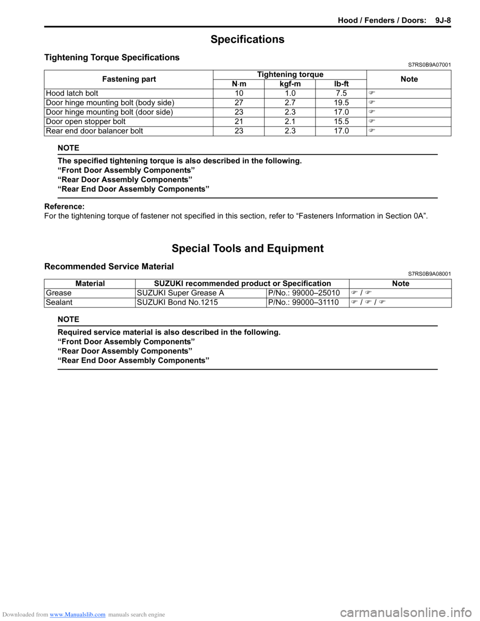
Tightening Torque SpecificationsS7RS0B9A07001
NOTE
The specified tightening torque is also described in the following.
“Front Door Assembly Components”
“Rear Door Assembly Components”
“Rear End Door Assembly Components”
Reference:
For the tightening torque of fastener not specified in this section, refer to “Fasteners Information in Section 0A”.
Special Tools and Equipment
Recommended Service MaterialS7RS0B9A08001
NOTE
Required service material is also described in the following.
“Front Door Assembly Components”
“Rear Door Assembly Components”
“Rear End Door Assembly Components”
Fastening part Tightening torque
Note
N ⋅mkgf-mlb-ft
Hood latch bolt 10 1.0 7.5 �)
Door hinge mounting bolt (body side) 27 2.7 19.5 �)
Door hinge mounting bolt (door side) 23 2.3 17.0 �)
Door open stopper bolt 21 2.1 15.5 �)
Rear end door balancer bolt 23 2.3 17.0 �)
MaterialSUZUKI recommended product or Specification Note
Grease SUZUKI Super Grease A P/No.: 99000–25010�) / �)
Sealant SUZUKI Bond No.1215 P/No.: 99000–31110�) / �) / �)
Page 1378 of 1496
Downloaded from www.Manualslib.com manuals search engine 9K-1 Body Structure:
Body, Cab and Accessories
Body Structure
Repair Instructions
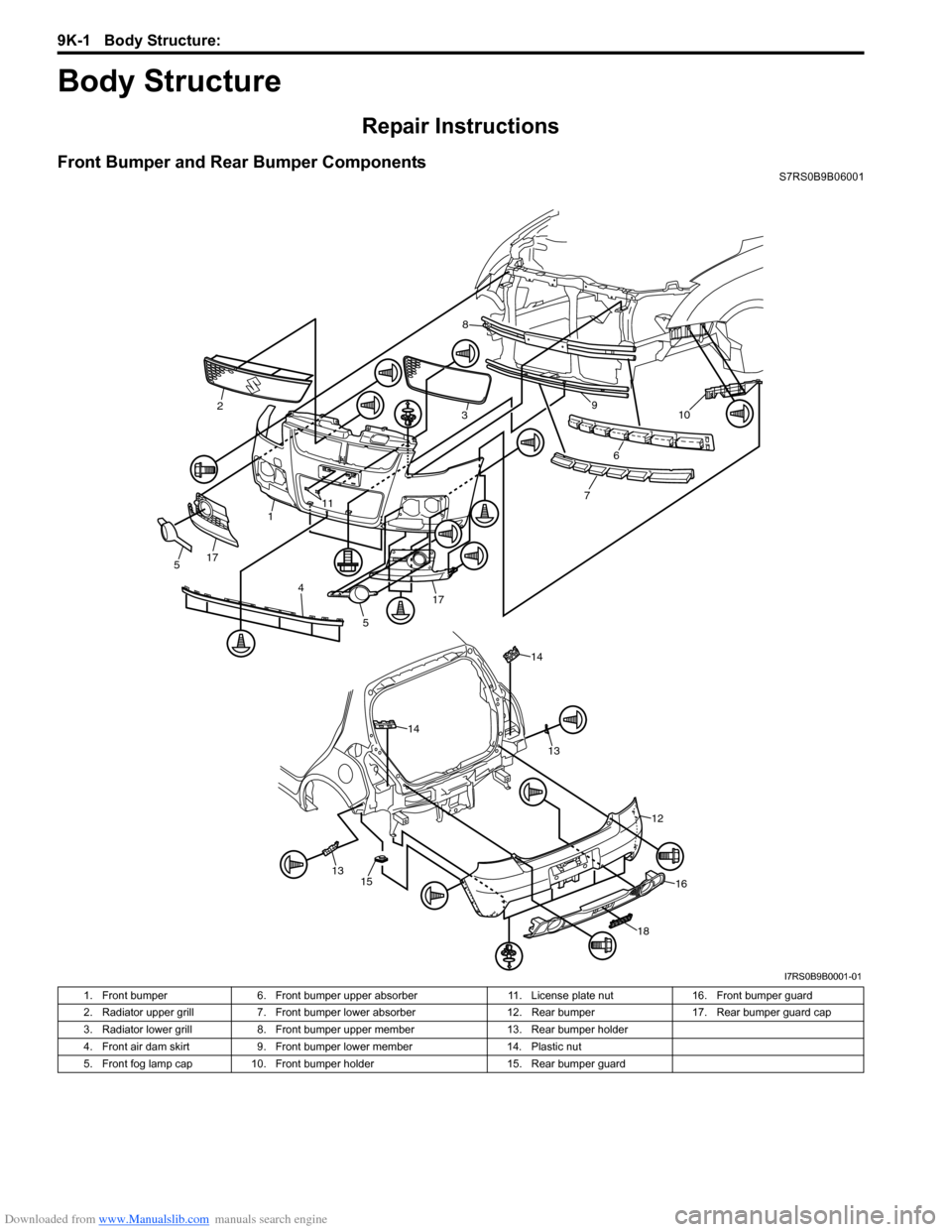
Front Bumper and Rear Bumper ComponentsS7RS0B9B06001
10
6
79
8
32
1
5
4 1117
175
1315
14
12
16
18
14
13
I7RS0B9B0001-01
1. Front bumper
6. Front bumper upper absorber 11. License plate nut16. Front bumper guard
2. Radiator upper grill 7. Front bumper lower absorber 12. Rear bumper17. Rear bumper guard cap
3. Radiator lower grill 8. Front bumper upper member 13. Rear bumper holder
4. Front air dam skirt 9. Front bumper lower member 14. Plastic nut
5. Front fog lamp cap 10. Front bumper holder 15. Rear bumper guard
Page 1380 of 1496
Downloaded from www.Manualslib.com manuals search engine 9K-3 Body Structure:
Specifications
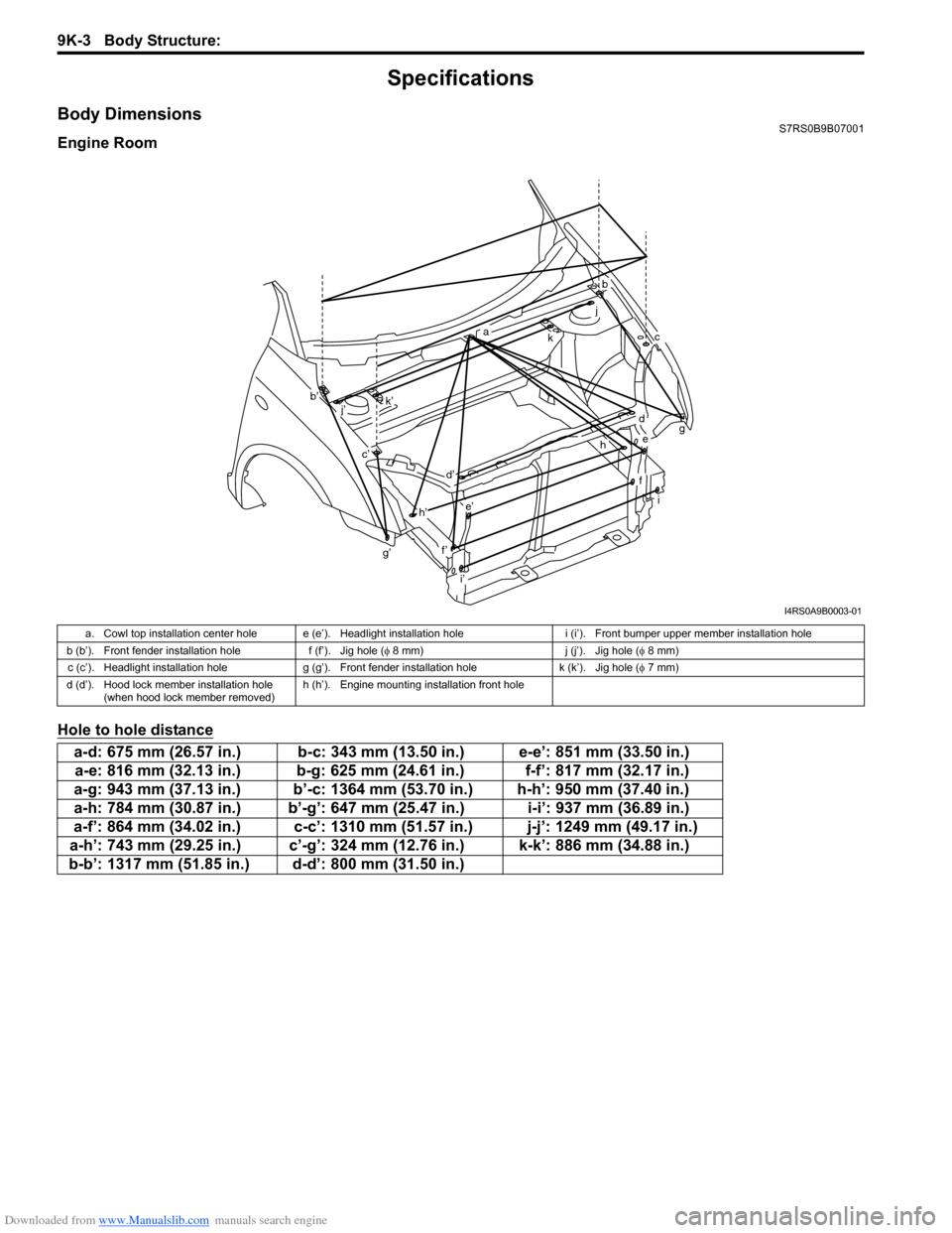
Body DimensionsS7RS0B9B07001
Engine Room
Hole to hole distance
g’
b
ckg
i
a
b’
c’
d
d’
e
e’
f’
f
h
h’
i’ j
k’
j’
I4RS0A9B0003-01
a. Cowl top installation center hole e (e’). Headlight installation hole i (i’). Front bumper upper member installation hole
b (b’). Front fender installation hole f (f’). Jig hole (φ 8 mm) j (j’). Jig hole (φ 8 mm)
c (c’). Headlight installation hole g (g’). Front fender installation hole k (k’). Jig hole (φ 7 mm)
d (d’). Hood lock member installation hole (when hood lock member removed) h (h’). Engine mounting installation front hole
a-d: 675 mm (26.57 in.) b-c: 343 mm (13.50 in.) e-e’: 851 mm (33.50 in.)
a-e: 816 mm (32.13 in.) b-g: 625 mm (24.61 in.) f-f’: 817 mm (32.17 in.)
a-g: 943 mm (37.13 in.) b’-c: 1364 mm (53.70 in.) h-h’: 950 mm (37.40 in.)
a-h: 784 mm (30.87 in.) b’-g’: 647 mm (25.47 in.) i-i’: 937 mm (36.89 in.)
a-f’: 864 mm (34.02 in.) c-c’: 1310 mm (51.57 in.) j-j’: 1249 mm (49.17 in.)
a-h’: 743 mm (29.25 in.) c’-g’: 324 mm (12.76 in.) k-k’: 886 mm (34.88 in.)
b-b’: 1317 mm (51.85 in.) d-d’: 800 mm (31.50 in.)
Page 1382 of 1496

Downloaded from www.Manualslib.com manuals search engine 9K-5 Body Structure:
Side Body
Hole to hole distance
Hole to hole distance
I4RS0A9B0005-02
a (a’). Jig hole (φ 8 mm) e (e’). Rear door lower hinge installation rear hole i (i’). Jig hole ( φ 10 mm)
b (b’). Front door upper hinge installation upper hole f (f’). Rear door upper hinge installation upper hole j (j’). Rear door switc h installation hole (large hole)
c (c’). Front door lower hinge installation lower hole g (g’). Jig hole ( φ 10 mm) k (k’). Rear side sill scuff installation hole
d (d’). Bleeding hole h (h’). Curtain air bag clip installation hole
a-d: 1055 mm (41.54 in.) c-e: 1021 mm (40.20 in.) f-j: 835 mm (32.87 in.) a-f: 747 mm (29.41 in.) c-f: 1123 mm (44.21 in.) h-i: 601 mm (23.66 in.)
a-g: 378 mm (14.88 in.) d-g: 1129 mm (44.45 in.) h-j: 817 mm (32.17 in.)
b-c: 383 mm (15.08 in.) e-f: 354 mm (13.94 in.) h-k: 1097 mm (43.19 in.)
b-e: 1085 mm (42.72 in.) e-j: 946 mm (37.24 in.) i-k: 1153 mm (45.39 in.) b-f: 1061 mm (41.77 in.) f-i: 926 mm (36.46 in.)
a-a’: 1039 mm (40.91 in.) e-e’: 1474 mm (58.03 in.) i-i’: 1009 mm (39.72 in.)
b-b’: 1461 mm (57.52 in.) f-f’: 1468 mm (57.80 in.) j-j’: 1327 mm (52.24 in.) c-c’: 1489 mm (58.62 in.) g-g’: 1018 mm (40.08 in.) k-k’: 1472 mm (57.95 in.)
d-d’: 1472 mm (57.95 in.) h-h’: 1022 mm (40.24 in.)
Page 1383 of 1496
Downloaded from www.Manualslib.com manuals search engine Body Structure: 9K-6
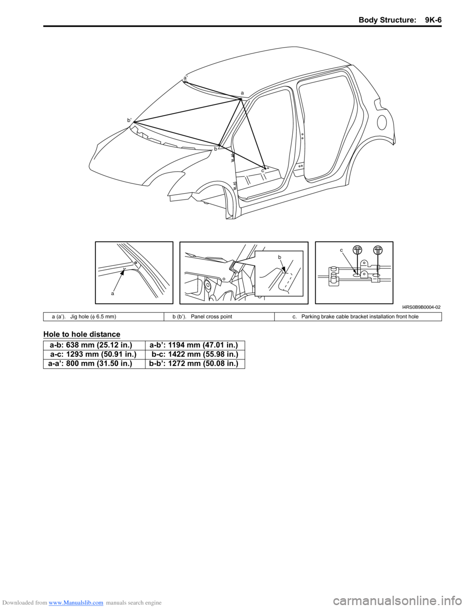
Hole to hole distance
a
cb
a’
a
bc
b’
I4RS0B9B0004-02
a (a’). Jig hole (φ 6.5 mm) b (b’). Panel cross point c. Parking brake cable bracket installation front hole
a-b: 638 mm (25.12 in.) a-b’: 1194 mm (47.01 in.)
a-c: 1293 mm (50.91 in.) b-c: 1422 mm (55.98 in.)
a-a’: 800 mm (31.50 in.) b-b’: 1272 mm (50.08 in.)
Page 1384 of 1496
Downloaded from www.Manualslib.com manuals search engine 9K-7 Body Structure:
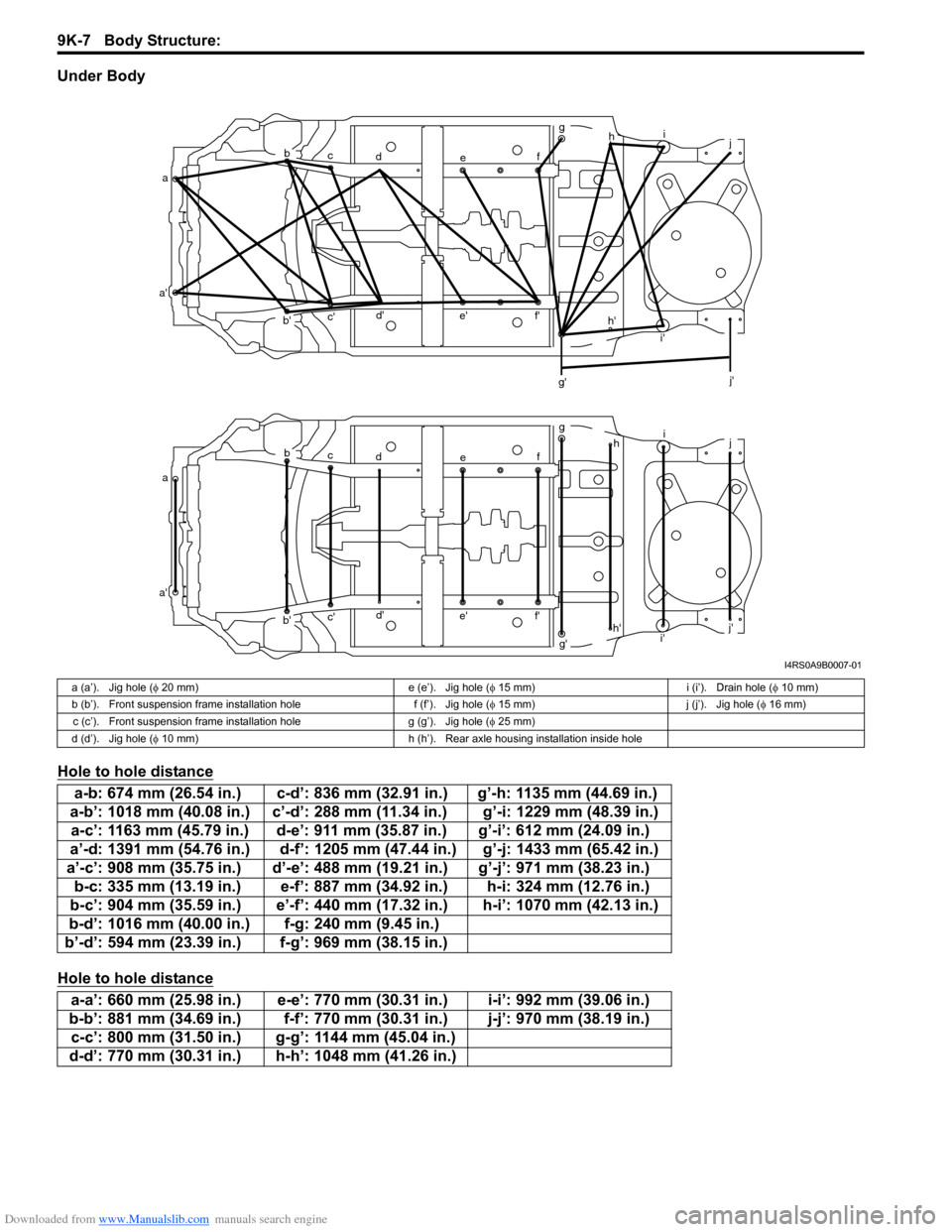
Under Body
Hole to hole distance
Hole to hole distance
ab
c d e fg
h i
j
a' b'c'
d'
e' f'
g' i'
j'
a b
c d e fg
hi
j
a' b'c'
d'
e' f'
g'h'
i' j'
h'
I4RS0A9B0007-01
a (a’). Jig hole (
φ 20 mm) e (e’). Jig hole ( φ 15 mm) i (i’). Drain hole ( φ 10 mm)
b (b’). Front suspension frame installation hole f (f’). Jig hole ( φ 15 mm) j (j’). Jig hole ( φ 16 mm)
c (c’). Front suspension frame installation hole g (g’). Jig hole (φ 25 mm)
d (d’). Jig hole ( φ 10 mm) h (h’). Rear axle housing installation inside hole
a-b: 674 mm (26.54 in.) c-d’: 836 mm (32.91 in.) g’-h: 1135 mm (44.69 in.)
a-b’: 1018 mm (40.08 in.) c’-d’: 288 mm (11.34 in.) g’-i: 1229 mm (48.39 in.) a-c’: 1163 mm (45.79 in.) d-e’: 911 mm (35.87 in.) g’-i’: 612 mm (24.09 in.)
a’-d: 1391 mm (54.76 in.) d-f’: 1205 mm (47.44 in.) g’-j: 1433 mm (65.42 in.)
a’-c’: 908 mm (35.75 in.) d’-e’: 488 mm (1 9.21 in.) g’-j’: 971 mm (38.23 in.)
b-c: 335 mm (13.19 in.) e-f’: 887 mm (34.92 in.) h-i: 324 mm (12.76 in.)
b-c’: 904 mm (35.59 in.) e’-f’: 440 mm (17.32 in.) h-i’: 1070 mm (42.13 in.)
b-d’: 1016 mm (40.00 in.) f-g: 240 mm (9.45 in.)
b’-d’: 594 mm (23.39 in.) f-g’: 969 mm (38.15 in.)
a-a’: 660 mm (25.98 in.) e-e’: 770 mm (30.31 in.) i-i’: 992 mm (39.06 in.)
b-b’: 881 mm (34.69 in.) f-f’: 770 mm (30.31 in.) j-j’: 970 mm (38.19 in.) c-c’: 800 mm (31.50 in.) g-g’: 1144 mm (45.04 in.)
d-d’: 770 mm (30.31 in.) h-h’: 1048 mm (41.26 in.)
Page 1385 of 1496
Downloaded from www.Manualslib.com manuals search engine Body Structure: 9K-8
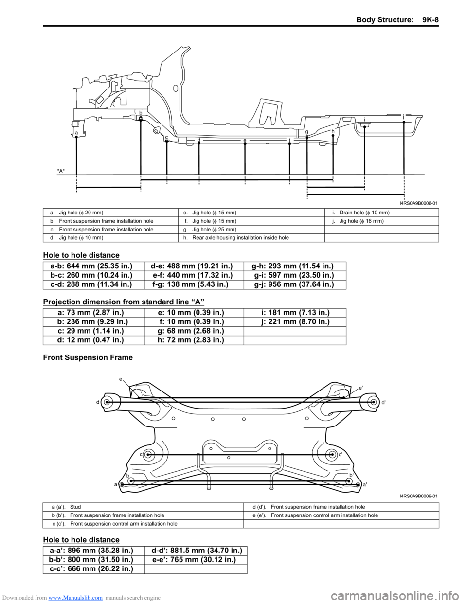
Hole to hole distance
Projection dimension from standard line “A”
Front Suspension Frame
Hole to hole distance
i
g
f
e
d
c
ab
"A"j
h
I4RS0A9B0008-01
a. Jig hole ( φ 20 mm) e. Jig hole ( φ 15 mm) i. Drain hole ( φ 10 mm)
b. Front suspension frame installation hole f. Jig hole (φ 15 mm) j. Jig hole (φ 16 mm)
c. Front suspension frame installation hole g. Jig hole ( φ 25 mm)
d. Jig hole ( φ 10 mm) h. Rear axle housing installation inside hole
a-b: 644 mm (25.35 in.) d-e: 488 mm (19.21 in.) g-h: 293 mm (11.54 in.)
b-c: 260 mm (10.24 in.) e-f: 440 mm (17.32 in.) g-i: 597 mm (23.50 in.)
c-d: 288 mm (11.34 in.) f-g: 138 mm (5.43 in.) g-j: 956 mm (37.64 in.)
a: 73 mm (2.87 in.) e: 10 mm (0.39 in.) i: 181 mm (7.13 in.)
b: 236 mm (9.29 in.) f: 10 mm (0.39 in.) j: 221 mm (8.70 in.) c: 29 mm (1.14 in.) g: 68 mm (2.68 in.)
d: 12 mm (0.47 in.) h: 72 mm (2.83 in.)
a b c
d
e
a'
b'
c' d'
e'
I4RS0A9B0009-01
a (a’). Stud
d (d’). Front suspension frame installation hole
b (b’). Front suspension frame installation hole e (e’). Front suspension control arm installation hole
c (c’). Front suspension control arm installation hole
a-a’: 896 mm (35.28 in.) d-d’: 881.5 mm (34.70 in.)
b-b’: 800 mm (31.50 in.) e-e’: 765 mm (30.12 in.) c-c’: 666 mm (26.22 in.)
Page 1386 of 1496
Downloaded from www.Manualslib.com manuals search engine 9K-9 Body Structure:
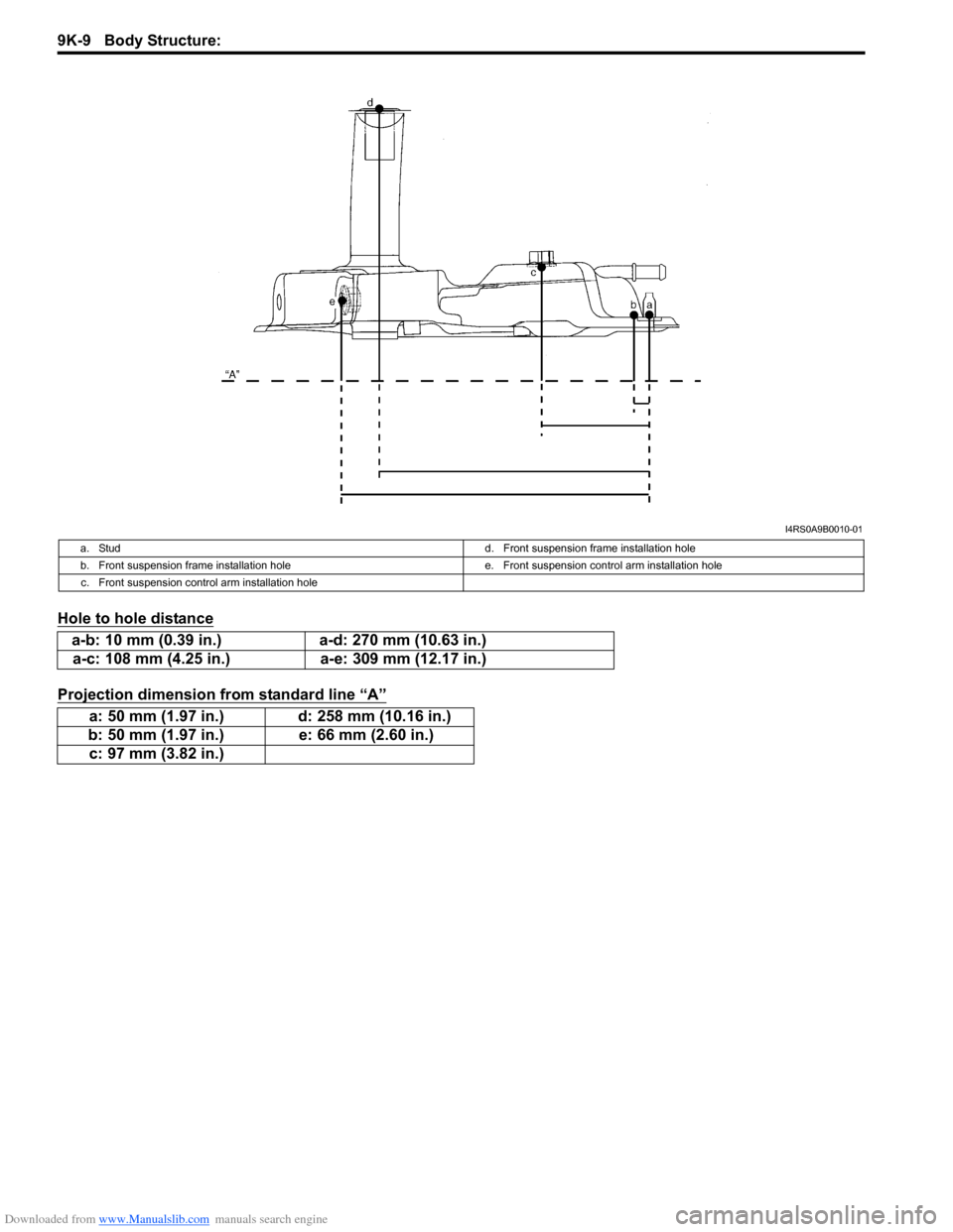
Hole to hole distance
Projection dimension from standard line “A”
I4RS0A9B0010-01
a. Studd. Front suspension frame installation hole
b. Front suspension frame installation hole e. Front suspension control arm installation hole
c. Front suspension control arm installation hole
a-b: 10 mm (0.39 in.) a-d: 270 mm (10.63 in.)
a-c: 108 mm (4.25 in.) a-e: 309 mm (12.17 in.)
a: 50 mm (1.97 in.) d: 258 mm (10.16 in.)
b: 50 mm (1.97 in.) e: 66 mm (2.60 in.)
c: 97 mm (3.82 in.)
Page 1402 of 1496
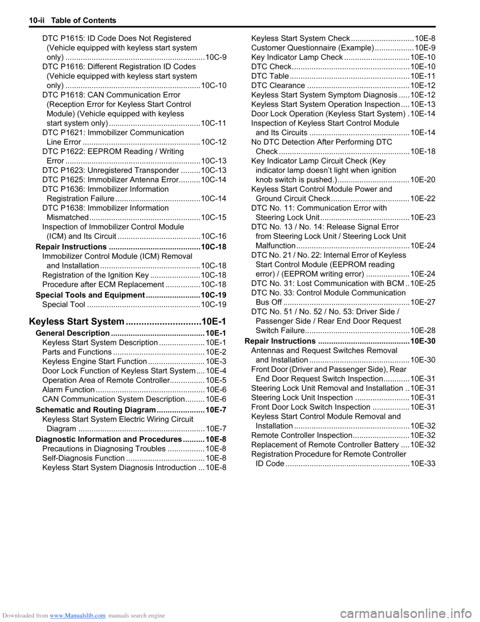
Downloaded from www.Manualslib.com manuals search engine 10-ii Table of Contents
DTC P1615: ID Code Does Not Registered (Vehicle equipped with keyless start system
only) ................................................................10C-9
DTC P1616: Different Registration ID Codes (Vehicle equipped with keyless start system
only) ..............................................................10C-10
DTC P1618: CAN Communication Error (Reception Error for Keyless Start Control
Module) (Vehicle equipped with keyless
start system only) ..........................................10C-11
DTC P1621: Immobilizer Communication Line Error ......................................................10C-12
DTC P1622: EEPROM Reading / Writing Error ..............................................................10C-13
DTC P1623: Unregistered Transponder .........10C-13
DTC P1625: Immobilizer An tenna Error..........10C-14
DTC P1636: Immobilizer Information Registration Failure .......................................10C-14
DTC P1638: Immobilizer Information Mismatched ...................................................10C-15
Inspection of Immobilizer Control Module (ICM) and Its Circuit ....... ...............................10C-16
Repair Instructions ........... ...............................10C-18
Immobilizer Control Mo dule (ICM) Removal
and Installation ..............................................10C-18
Registration of the Ignition Key .......................10C-18
Procedure after ECM Replacement ................10C-18
Special Tools and Equipmen t .........................10C-19
Special Tool ....................................................10C-19
Keyless Start System ....... ......................10E-1
General Description ........................................... 10E-1
Keyless Start System Description ..................... 10E-1
Parts and Functions .......................................... 10E-2
Keyless Engine Start Function .......................... 10E-3
Door Lock Function of Keyless Start System .... 10E-4
Operation Area of Remote Controller................ 10E-5
Alarm Function .................................................. 10E-6
CAN Communication System Description......... 10E-6
Schematic and Routing Diagram ...................... 10E-7 Keyless Start System El ectric Wiring Circuit
Diagram .......................................................... 10E-7
Diagnostic Information and Procedures .......... 10E-8 Precautions in Diagnosing Troubles ................. 10E-8
Self-Diagnosis Function .................................... 10E-8
Keyless Start System Diagn osis Introduction ... 10E-8 Keyless Start System Chec
k ............................. 10E-8
Customer Questionnaire (E xample) .................. 10E-9
Key Indicator Lamp Check .............................. 10E-10
DTC Check...................................................... 10E-10
DTC Table ....................................................... 10E-11
DTC Clearance ............................................... 10E-12
Keyless Start System Symp tom Diagnosis ..... 10E-12
Keyless Start System Operation Inspection .... 10E-13
Door Lock Operation (Keyless Start System) . 10E-14
Inspection of Keyless Start Control Module and Its Circuits .............................................. 10E-14
No DTC Detection After Performing DTC Check ............................................................ 10E-18
Key Indicator Lamp Circuit Check (Key indicator lamp doesn’t light when ignition
knob switch is pushed.) ................................. 10E-20
Keyless Start Control Module Power and Ground Circuit Check .................................... 10E-22
DTC No. 11: Communi cation Error with
Steering Lock Unit ......................................... 10E-23
DTC No. 13 / No. 14: Release Signal Error from Steering Lock Unit / Steering Lock Unit
Malfunction .................................................... 10E-24
DTC No. 21 / No. 22: Internal Error of Keyless Start Control Module (EEPROM reading
error) / (EEPROM writing error) ............ ........ 10E-24
DTC No. 31: Lost Commun ication with BCM .. 10E-25
DTC No. 33: Control Module Communication
Bus Off .......................................................... 10E-27
DTC No. 51 / No. 52 / No. 53: Driver Side / Passenger Side / Rear End Door Request
Switch Failure................................................ 10E-28
Repair Instructions ............ .............................. 10E-30
Antennas and Request Switches Removal and Installation .............................................. 10E-30
Front Door (Driver and Passenger Side), Rear End Door Request Switch Inspection............ 10E-31
Steering Lock Unit Removal and Installation .. 10E-31
Steering Lock Unit Inspection ......................... 10E-31
Front Door Lock Switch In spection ................. 10E-31
Keyless Start Control Module Removal and Installation ..................................................... 10E-32
Remote Controller Inspection.......................... 10E-32
Replacement of Remote Controller Battery .... 10E-32
Registration Procedure for Remote Controller
ID Code ......................................................... 10E-33