AC line SUZUKI SWIFT 2006 2.G Service Owner's Guide
[x] Cancel search | Manufacturer: SUZUKI, Model Year: 2006, Model line: SWIFT, Model: SUZUKI SWIFT 2006 2.GPages: 1496, PDF Size: 34.44 MB
Page 230 of 1496
Downloaded from www.Manualslib.com manuals search engine 1A-180 Engine General Information and Diagnosis:
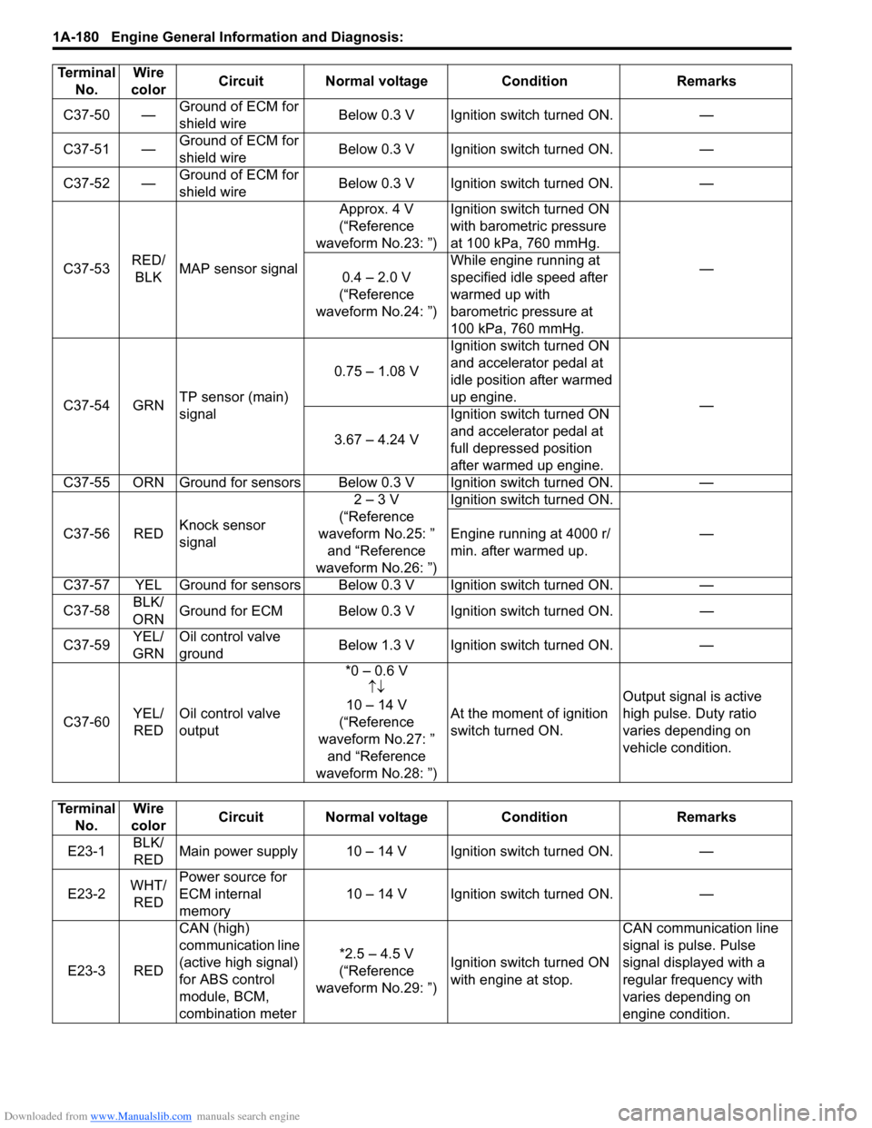
C37-50 βGround of ECM for
shield wire Below 0.3 V Ignition switch turned ON. β
C37-51 β Ground of ECM for
shield wire Below 0.3 V Ignition switch turned ON. β
C37-52 β Ground of ECM for
shield wire Below 0.3 V Ignition switch turned ON. β
C37-53 RED/
BLK MAP sensor signal Approx. 4 V
(βReference
waveform No.23: β) Ignition switch turned ON
with barometric pressure
at 100 kPa, 760 mmHg.
β
0.4 β 2.0 V
(βReference
waveform No.24: β) While engine running at
specified idle speed after
warmed up with
barometric pressure at
100 kPa, 760 mmHg.
C37-54 GRN TP sensor (main)
signal 0.75 β 1.08 V
Ignition switch turned ON
and accelerator pedal at
idle position after warmed
up engine.
β
3.67 β 4.24 V Ignition switch turned ON
and accelerator pedal at
full depressed position
after warmed up engine.
C37-55 ORN Ground for sensors Below 0.3 V Ignition switch turned ON. β
C37-56 RED Knock sensor
signal 2 β 3 V
(βReference
waveform No.25: β and βReference
waveform No.26: β) Ignition switch turned ON.
β
Engine running at 4000 r/
min. after warmed up.
C37-57 YEL Ground for sensors Below 0.3 V Ignition switch turned ON. β
C37-58 BLK/
ORN Ground for ECM Below 0.3 V Ignition switch turned ON.
β
C37-59 YEL/
GRN Oil control valve
ground
Below 1.3 V Ignition switch turned ON.
β
C37-60 YEL/
RED Oil control valve
output *0 β 0.6 V
ββ
10 β 14 V
(βReference
waveform No.27: β and βReference
waveform No.28: β) At the moment of ignition
switch turned ON.
Output signal is active
high pulse. Duty ratio
varies depending on
vehicle condition.
Terminal
No. Wire
color Circuit Normal voltage
ConditionRemarks
Terminal
No. Wire
color Circuit Normal voltage Condition Remarks
E23-1 BLK/
RED Main power supply 10 β 14 V Ignition switch turned ON. β
E23-2 WHT/
RED Power source for
ECM internal
memory
10 β 14 V Ignition switch turned ON. β
E23-3 RED CAN (high)
communication line
(active high signal)
for ABS control
module, BCM,
combination meter *2.5 β 4.5 V
(βReference
waveform No.29: β) Ignition switch turned ON
with engine at stop. CAN communication line
signal is pulse. Pulse
signal displayed with a
regular frequency with
varies depending on
engine condition.
Page 231 of 1496
Downloaded from www.Manualslib.com manuals search engine Engine General Information and Diagnosis: 1A-181
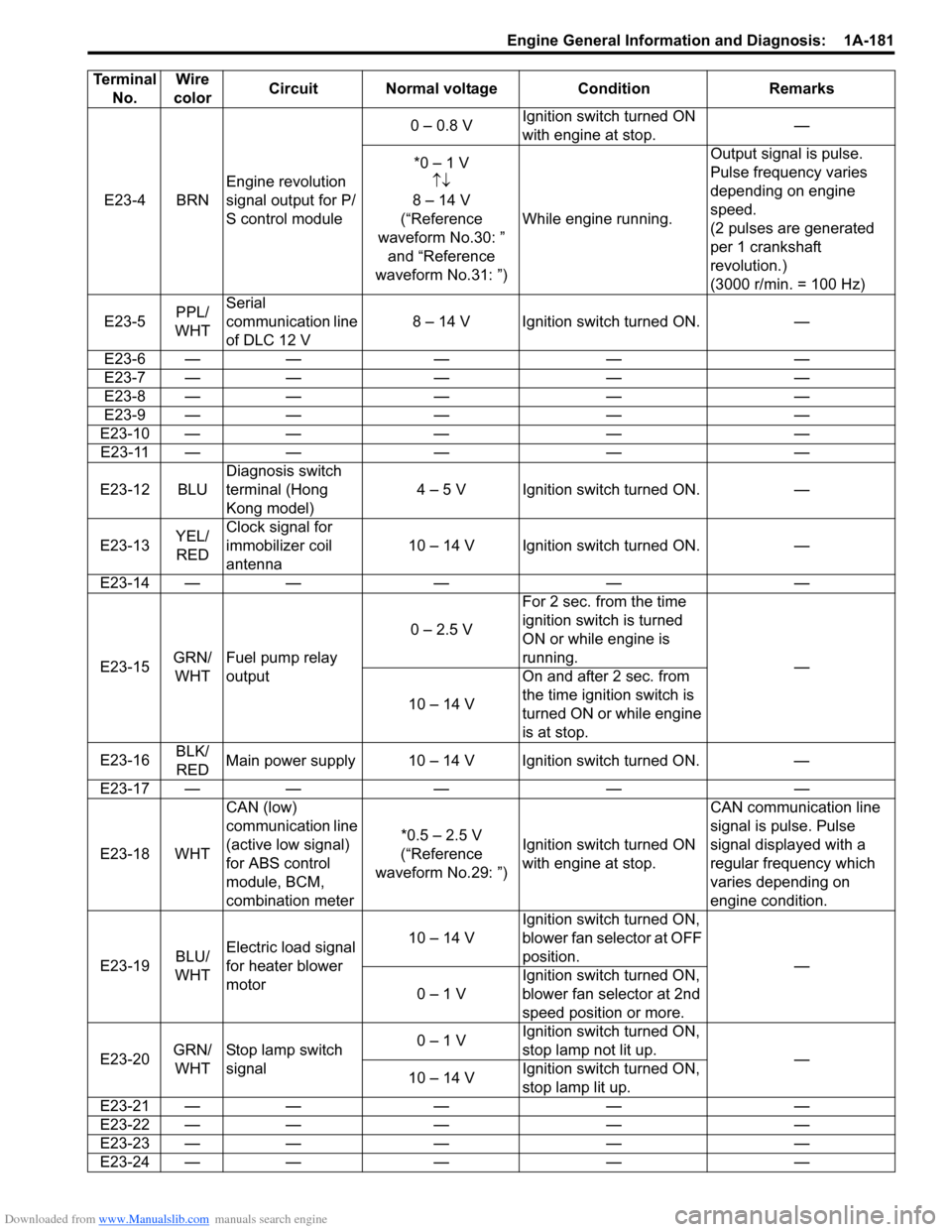
E23-4 BRNEngine revolution
signal output for P/
S control module 0 β 0.8 V
Ignition switch turned ON
with engine at stop. β
*0 β 1 V ββ
8 β 14 V
(βReference
waveform No.30: β and βReference
waveform No.31: β) While engine running. Output signal is pulse.
Pulse frequency varies
depending on engine
speed.
(2 pulses are generated
per 1 crankshaft
revolution.)
(3000 r/min. = 100 Hz)
E23-5 PPL/
WHT Serial
communication line
of DLC 12 V
8 β 14 V Ignition switch turned ON. β
E23-6 β β β β β
E23-7 β β β β β
E23-8 β β β β β
E23-9 β β β β β
E23-10 β β β β β E23-11 β β β β β
E23-12 BLU Diagnosis switch
terminal (Hong
Kong model) 4 β 5 V Ignition switch turned ON. β
E23-13 YEL/
RED Clock signal for
immobilizer coil
antenna
10 β 14 V Ignition switch turned ON. β
E23-14 β β β β β
E23-15 GRN/
WHT Fuel pump relay
output 0 β 2.5 V
For 2 sec. from the time
ignition switch is turned
ON or while engine is
running.
β
10 β 14 V On and after 2 sec. from
the time ignition switch is
turned ON or while engine
is at stop.
E23-16 BLK/
RED Main power supply 10 β 14 V Ignition switch turned ON. β
E23-17 β β β β β
E23-18 WHT CAN (low)
communication line
(active low signal)
for ABS control
module, BCM,
combination meter *0.5 β 2.5 V
(βReference
waveform No.29: β) Ignition switch turned ON
with engine at stop. CAN communication line
signal is pulse. Pulse
signal displayed with a
regular frequency which
varies depending on
engine condition.
E23-19 BLU/
WHT Electric load signal
for heater blower
motor 10 β 14 V
Ignition switch turned ON,
blower fan selector at OFF
position.
β
0 β 1 V Ignition switch turned ON,
blower fan selector at 2nd
speed position or more.
E23-20 GRN/
WHT Stop lamp switch
signal 0 β 1 V
Ignition switch turned ON,
stop lamp not lit up.
β
10 β 14 V Ignition switch turned ON,
stop lamp lit up.
E23-21 β β β β β
E23-22 β β β β β
E23-23 β β β β β
E23-24 β β β β β
Terminal
No. Wire
color Circuit Normal voltage Condition Remarks
Page 232 of 1496
Downloaded from www.Manualslib.com manuals search engine 1A-182 Engine General Information and Diagnosis:
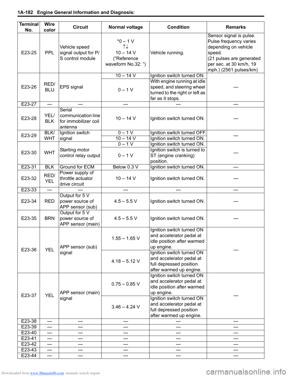
E23-25 PPLVehicle speed
signal output for P/
S control module *0 β 1 V
ββ
10 β 14 V
(βReference
waveform No.32: β) Vehicle running. Sensor signal is pulse.
Pulse frequency varies
depending on vehicle
speed.
(21 pulses are generated
per sec. at 30 km/h, 19
mph.) (2561 pulses/km)
E23-26 RED/
BLU EPS signal 10 β 14 V Ignition switch turned ON.
β
0 β 1 V With engine running at idle
speed, and steering wheel
turned to the right or left as
far as it stops.
E23-27 β β β β β
E23-28 YEL/
BLK Serial
communication line
for immobilizer coil
antenna
10 β 14 V Ignition switch turned ON. β
E23-29 BLK/
WHT Ignition switch
signal 0 β 1 V Ignition switch turned OFF.
β
10 β 14 V Ignition switch turned ON.
E23-30 WHT Starting motor
control relay output 0 β 1 V Ignition switch turned ON.
β
0 β 1 V Ignition switch is turned to
ST (engine cranking)
position.
E23-31 BLK Ground for ECM Below 0.3 V Ignition switch turned ON. β
E23-32 RED/
YEL Power supply of
throttle actuator
drive circuit
10 β 14 V Ignition switch turned ON. β
E23-33 β β β β β
E23-34 RED Output for 5 V
power source of
APP sensor (sub) 4.5 β 5.5 V Ignition switch turned ON. β
E23-35 BRN Output for 5 V
power source of
APP sensor (main) 4.5 β 5.5 V Ignition switch turned ON. β
E23-36 YEL APP sensor (sub)
signal 1.55 β 1.65 V
Ignition switch turned ON
and accelerator pedal at
idle position after warmed
up engine.
β
4.18 β 5.12 V Ignition switch turned ON
and accelerator pedal at
full depressed position
after warmed up engine.
E23-37 YEL APP sensor (main)
signal 0.75 β 0.85 V
Ignition switch turned ON
and accelerator pedal at
idle position after warmed
up engine.
β
3.46 β 4.24 V Ignition switch turned ON
and accelerator pedal at
full depressed position
after warmed up engine.
E23-38 β β β β β
E23-39 β β β β β
E23-40 β β β β β
E23-41 β β β β β
E23-42 β β β β β
E23-43 β β β β β
E23-44 β β β β β
Terminal
No. Wire
color Circuit Normal voltage Condition Remarks
Page 237 of 1496
Downloaded from www.Manualslib.com manuals search engine Engine General Information and Diagnosis: 1A-187
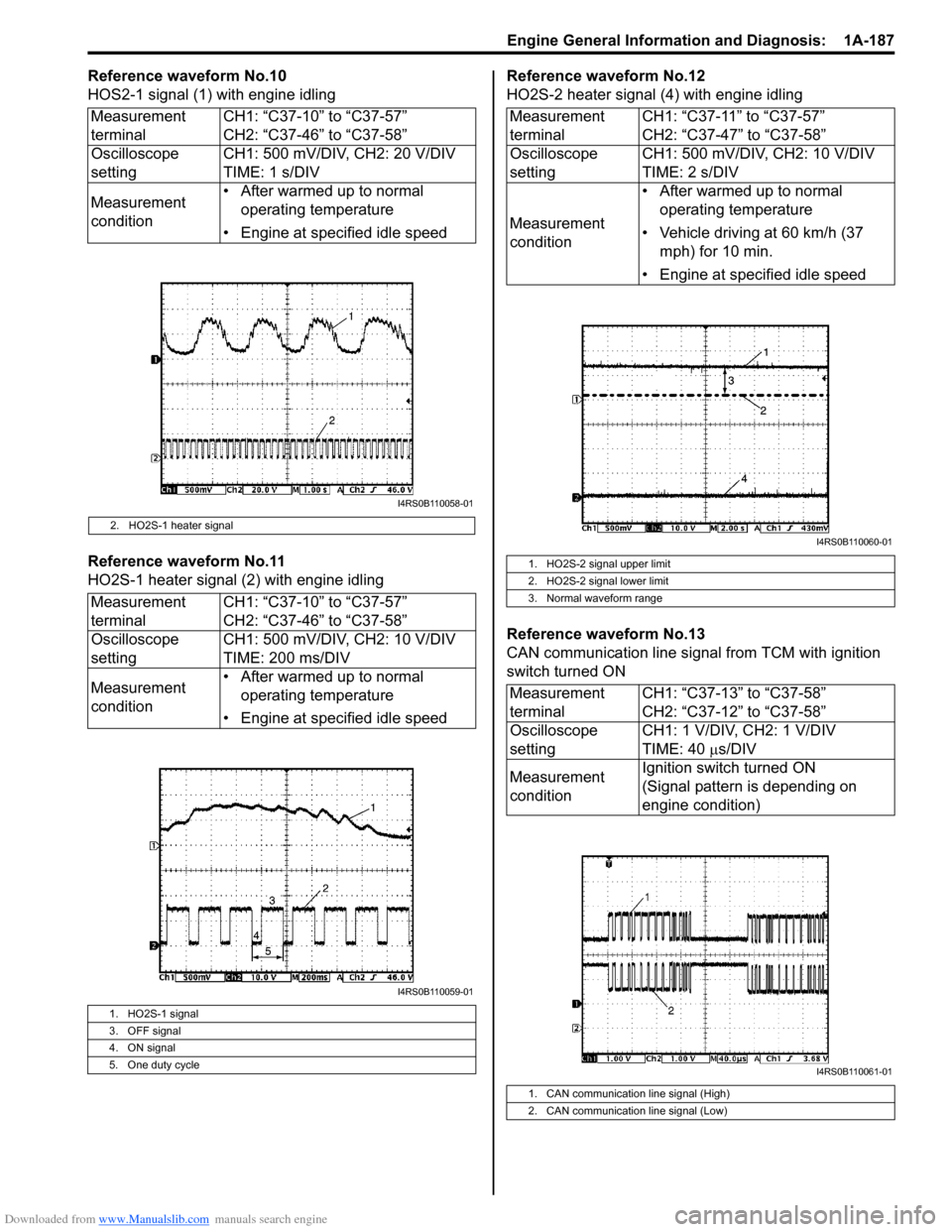
Reference waveform No.10
HOS2-1 signal (1) with engine idling
Reference waveform No.11
HO2S-1 heater signal (2) with engine idlingReference waveform No.12
HO2S-2 heater signal (4) with engine idling
Reference waveform No.13
CAN communication line signal from TCM with ignition
switch turned ON
Measurement
terminal
CH1: βC37-10β to βC37-57β
CH2: βC37-46β to βC37-58β
Oscilloscope
setting CH1: 500 mV/DIV, CH2: 20 V/DIV
TIME: 1 s/DIV
Measurement
condition β’ After warmed up to normal
operating temperature
β’ Engine at specified idle speed
2. HO2S-1 heater signal
Measurement
terminal CH1: βC37-10β to βC37-57β
CH2: βC37-46β to βC37-58β
Oscilloscope
setting CH1: 500 mV/DIV, CH2: 10 V/DIV
TIME: 200 ms/DIV
Measurement
condition β’ After warmed up to normal
operating temperature
β’ Engine at specified idle speed
1. HO2S-1 signal
3. OFF signal
4. ON signal
5. One duty cycle
I4RS0B110058-01
I4RS0B110059-01
Measurement
terminal CH1: βC37-11β to βC37-57β
CH2: βC37-47β to βC37-58β
Oscilloscope
setting CH1: 500 mV/DIV, CH2: 10 V/DIV
TIME: 2 s/DIV
Measurement
condition β’ After warmed up to normal
operating temperature
β’ Vehicle driving at 60 km/h (37 mph) for 10 min.
β’ Engine at specified idle speed
1. HO2S-2 signal upper limit
2. HO2S-2 signal lower limit
3. Normal waveform range
Measurement
terminal CH1: βC37-13β to βC37-58β
CH2: βC37-12β to βC37-58β
Oscilloscope
setting CH1: 1 V/DIV, CH2: 1 V/DIV
TIME: 40
Β΅s/DIV
Measurement
condition Ignition switch turned ON
(Signal pattern is depending on
engine condition)
1. CAN communication line signal (High)
2. CAN communication line signal (Low)
I4RS0B110060-01
I4RS0B110061-01
Page 242 of 1496
Downloaded from www.Manualslib.com manuals search engine 1A-192 Engine General Information and Diagnosis:
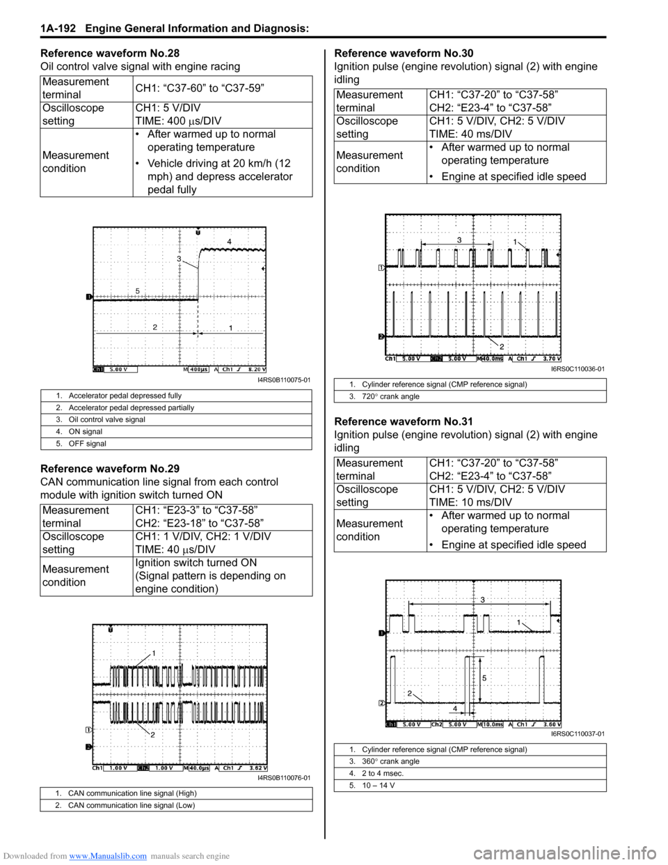
Reference waveform No.28
Oil control valve signal with engine racing
Reference waveform No.29
CAN communication line signal from each control
module with ignition switch turned ONReference waveform No.30
Ignition pulse (engine revolution) signal (2) with engine
idling
Reference waveform No.31
Ignition pulse (engine revolution) signal (2) with engine
idling
Measurement
terminal
CH1: βC37-60β to βC37-59β
Oscilloscope
setting CH1: 5 V/DIV
TIME: 400
Β΅s/DIV
Measurement
condition β’ After warmed up to normal
operating temperature
β’ Vehicle driving at 20 km/h (12 mph) and depress accelerator
pedal fully
1. Accelerator pedal depressed fully
2. Accelerator pedal depressed partially
3. Oil control valve signal
4. ON signal
5. OFF signal
Measurement
terminal CH1: βE23-3β to βC37-58β
CH2: βE23-18β to βC37-58β
Oscilloscope
setting CH1: 1 V/DIV, CH2: 1 V/DIV
TIME: 40
Β΅s/DIV
Measurement
condition Ignition switch turned ON
(Signal pattern is depending on
engine condition)
1. CAN communication line signal (High)
2. CAN communication line signal (Low)
I4RS0B110075-01
I4RS0B110076-01
Measurement
terminal
CH1: βC37-20β to βC37-58β
CH2: βE23-4β to βC37-58β
Oscilloscope
setting CH1: 5 V/DIV, CH2: 5 V/DIV
TIME: 40 ms/DIV
Measurement
condition β’ After warmed up to normal
operating temperature
β’ Engine at specified idle speed
1. Cylinder reference signal (CMP reference signal)
3. 720 Β° crank angle
Measurement
terminal CH1: βC37-20β to βC37-58β
CH2: βE23-4β to βC37-58β
Oscilloscope
setting CH1: 5 V/DIV, CH2: 5 V/DIV
TIME: 10 ms/DIV
Measurement
condition β’ After warmed up to normal
operating temperature
β’ Engine at specified idle speed
1. Cylinder reference signal (CMP reference signal)
3. 360 Β° crank angle
4. 2 to 4 msec.
5. 10 β 14 V
I6RS0C110036-01
I6RS0C110037-01
Page 254 of 1496
Downloaded from www.Manualslib.com manuals search engine 1A-204 Engine General Information and Diagnosis:
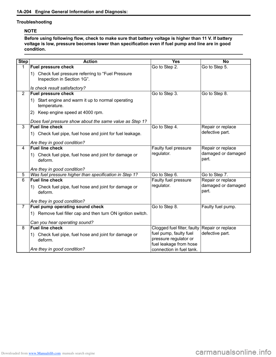
Troubleshooting
NOTE
Before using following flow, check to make sure that battery voltage is higher than 11 V. If battery
voltage is low, pressure becomes lower than specification even if fuel pump and line are in good
condition.
StepAction YesNo
1 Fuel pressure check
1) Check fuel pressure referring to βFuel Pressure
Inspection in Section 1Gβ.
Is check result satisfactory? Go to Step 2.
Go to Step 5.
2 Fuel pressure check
1) Start engine and warm it up to normal operating
temperature.
2) Keep engine speed at 4000 rpm.
Does fuel pressure show about the same value as Step 1? Go to Step 3.
Go to Step 8.
3 Fuel line check
1) Check fuel pipe, fuel hose and joint for fuel leakage.
Are they in good condition? Go to Step 4.
Repair or replace
defective part.
4 Fuel line check
1) Check fuel pipe, fuel hose and joint for damage or
deform.
Are they in good condition? Faulty fuel pressure
regulator.
Repair or replace
damaged or damaged
part.
5 Was fuel pressure higher than specification in Step 1? Go to Step 6.Go to Step 7.
6 Fuel line check
1) Check fuel pipe, fuel hose and joint for damage or
deform.
Are they in good condition? Faulty fuel pressure
regulator.
Repair or replace
damaged or damaged
part.
7 Fuel pump operating sound check
1) Remove fuel filler cap and th en turn ON ignition switch.
Can you hear operating sound? Go to Step 8.
Faulty fuel pump.
8 Fuel line check
1) Check fuel pipe, fuel hose and joint for damage or
deform.
Are they in good condition? Clogged fuel filter, faulty
fuel pump, faulty fuel
pressure regulator or
fuel leakage from hose
connection in fuel tank.Repair or replace
defective part.
Page 276 of 1496
Downloaded from www.Manualslib.com manuals search engine 1C-4 Engine Electrical Devices:
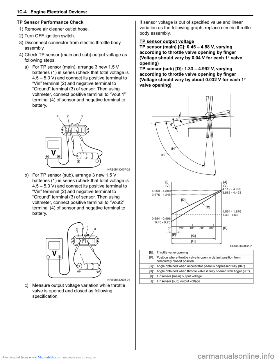
TP Sensor Performance Check1) Remove air cleaner outlet hose.
2) Turn OFF ignition switch.
3) Disconnect connector from electric throttle body assembly.
4) Check TP sensor (main and sub) output voltage as following steps.
a) For TP sensor (main), arrange 3 new 1.5 V batteries (1) in series (c heck that total voltage is
4.5 β 5.0 V) and connect its positive terminal to
βVinβ terminal (2) and negative terminal to
βGroundβ terminal (3) of sensor. Then using
voltmeter, connect positive terminal to βVout 1β
terminal (4) of sensor and negative terminal to
battery.
b) For TP sensor (sub), arrange 3 new 1.5 V batteries (1) in series (c heck that total voltage is
4.5 β 5.0 V) and connect its positive terminal to
βVinβ terminal (2) and negative terminal to
βGroundβ terminal (3) of sensor. Then using
voltmeter, connect positive terminal to βVout2β
terminal (4) of sensor and negative terminal to
battery.
c) Measure output voltage variation while throttle valve is opened and closed as following
specification. If sensor voltage is out of specified value and linear
variation as the following gra
ph, replace electric throttle
body assembly.
TP sensor output voltage
TP sensor (main) [C]: 0.45 β 4.88 V, varying
according to throttle valve opening by finger
(Voltage should vary by 0.04 V for each 1Β° valve
opening)
TP sensor (sub) [D]: 1.33 β 4.992 V, varying
according to throttle valve opening by finger
(Voltage should vary by about 0.032 V for each 1 Β°
valve opening)
1
42 3
I4RS0B130007-02
1
3
2 4
I4RS0B130008-01
[E]: Throttle valve opening
[F]: Position where throttle valve is open in default position from completely closed position
[G]: Angle obtained when accelerator pedal is depressed fully (84 Β°)
[H]: Angle obtained when throttle valve is fully opened with finger (96 Β°)
[I]: TP sensor (main) output voltage
[J]: TP sensor (sub) output voltage
[D]
[C][J]
(V)
[I]
(V)
[F] [G] [E]
0.45 - 0.75
0.684 - 0.996 3.675 - 4.245 4.000 - 4.880
1.33 - 1.63 1.564 - 1.876 3.883 - 4.453 4.112 - 4.992
[H]
I6RS0C130002-01
Page 277 of 1496
Downloaded from www.Manualslib.com manuals search engine Engine Electrical Devices: 1C-5
Electric Throttle Body System CalibrationS7RS0B1306004
NOTE
If working the service described under the
βPrecautions of Electric Throttle Body
System Calibration in Section 1Aβ perform
following steps for electric throttle body
system calibration.
1) If electric throttle body assembly and/or APP sensor
assembly are replaced, perform following steps.
a) Disconnect negative cable at battery for 20 seconds or more for the purpose of clearing
calibration data of closed throttle position from
memory in ECM.
b) Connect negative cable to battery.
2) Keep ignition switch at ON position for 5 seconds or more without running engine.
APP Sensor Assembly On-Vehicle InspectionS7RS0B1306005
1) Check that APP sensor a ssembly has been mounted
to vehicle body properly (no pinched floor carpet,
etc.).
If mounting is not pro perly, reinstall APP sensor
assembly properly refe rring to βAPP Sensor
Assembly Removal and Installationβ.
2) Connect scan tool to DLC with ignition switch turned OFF.
3) Turn ON ignition switch and select βData Listβ mode on scan tool.
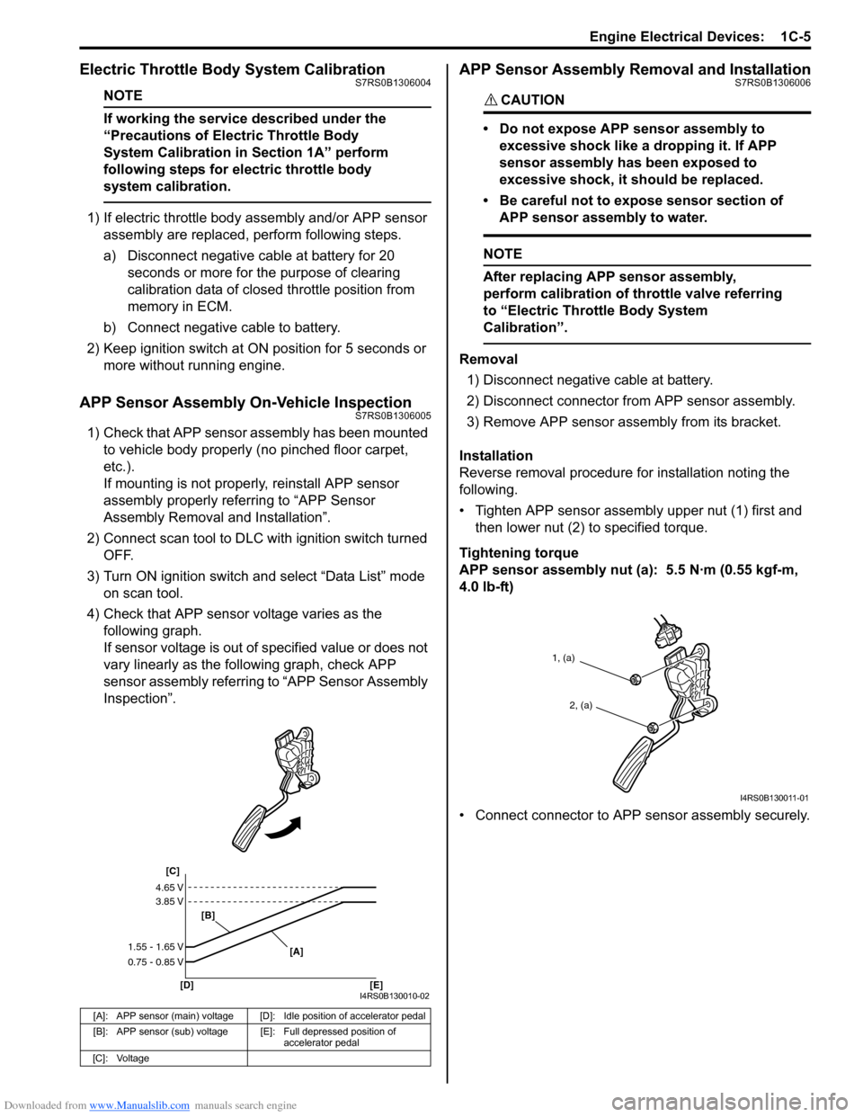
4) Check that APP sensor voltage varies as the following graph.
If sensor voltage is out of specified value or does not
vary linearly as the fo llowing graph, check APP
sensor assembly referring to βAPP Sensor Assembly
Inspectionβ.
APP Sensor Assembly Removal and InstallationS7RS0B1306006
CAUTION!
β’ Do not expose APP sensor assembly to
excessive shock like a dropping it. If APP
sensor assembly has been exposed to
excessive shock, it should be replaced.
β’ Be careful not to expose sensor section of APP sensor assembly to water.
NOTE
After replacing APP sensor assembly,
perform calibration of th rottle valve referring
to βElectric Throttle Body System
Calibrationβ.
Removal
1) Disconnect negative cable at battery.
2) Disconnect connector from APP sensor assembly.
3) Remove APP sensor asse mbly from its bracket.
Installation
Reverse removal procedure for installation noting the
following.
β’ Tighten APP sensor assembly upper nut (1) first and then lower nut (2) to specified torque.
Tightening torque
APP sensor assembly nut (a): 5.5 NΒ·m (0.55 kgf-m,
4.0 lb-ft)
β’ Connect connector to APP sensor assembly securely.
[A]: APP sensor (main) voltage [D]: Idle position of accelerator pedal
[B]: APP sensor (sub) voltage [E]: Full depressed position of
accelerator pedal
[C]: Voltage
[C]
[B]
[D] [E] [A]
4.65 V
3.85 V
1.55 - 1.65 V
0.75 - 0.85 V
I4RS0B130010-02
1, (a)
2, (a)
I4RS0B130011-01
Page 278 of 1496
Downloaded from www.Manualslib.com manuals search engine 1C-6 Engine Electrical Devices:
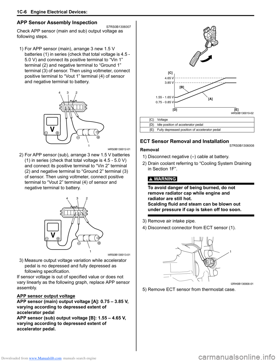
APP Sensor Assembly InspectionS7RS0B1306007
Check APP sensor (main and sub) output voltage as
following steps.
1) For APP sensor (main) , arrange 3 new 1.5 V
batteries (1) in series (check that total voltage is 4.5 -
5.0 V) and connect its positive terminal to βVin 1β
terminal (2) and negative terminal to βGround 1β
terminal (3) of sensor. Then using voltmeter, connect
positive terminal to βVout 1β terminal (4) of sensor
and negative terminal to battery.
2) For APP sensor (s ub), arrange 3 new 1.5 V batteries
(1) in series (check that total voltage is 4.5 - 5.0 V)
and connect its positive terminal to βVin 2β terminal
(2) and negative terminal to βGround 2β terminal (3)
of sensor. Then using volt meter, connect positive
terminal to βVout 2β terminal (4) of sensor and
negative termin al to battery.
3) Measure output voltage variation while accelerator pedal is no depressed and fully depressed as
following specification.
If sensor voltage is out of specified value or does not
vary linearly as the followin g graph, replace APP sensor
assembly.
APP sensor output voltage
APP sensor (main) output voltage [A]: 0.75 β 3.85 V,
varying according to depressed extent of
accelerator pedal
APP sensor (sub) output voltage [B]: 1.55 β 4.65 V,
varying according to depressed extent of
accelerator pedal.
ECT Sensor Removal and InstallationS7RS0B1306008
Removal
1) Disconnect negative (β) cable at battery.
2) Drain coolant referring to βCooling System Draining in Section 1Fβ.
WARNING!
To avoid danger of being burned, do not
remove radiator cap while engine and
radiator are still hot.
Scalding fluid and steam can be blown out
under pressure if cap is taken off too soon.
3) Remove air intake pipe.
4) Disconnect connector from ECT sensor (1).
5) Remove ECT sensor from thermostat case.
1
234I4RS0B130012-01
1
234I4RS0B130013-01
[C]: Voltage
[D]: Idle position of accelerator pedal
[E]: Fully depressed position of accelerator pedal
[C]
[B]
[D] [E] [A]
4.65 V
3.85 V
1.55 - 1.65 V
0.75 - 0.85 V
I4RS0B130010-02
1
I2RH0B130008-01
Page 286 of 1496
Downloaded from www.Manualslib.com manuals search engine 1D-1 Engine Mechanical:
Engine
Engine Mechanical
General Description
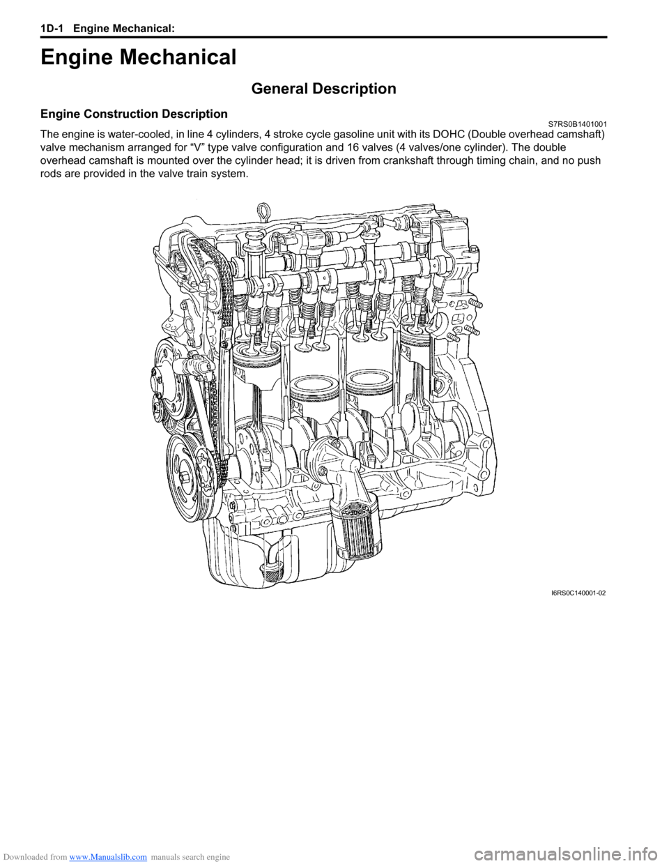
Engine Construction DescriptionS7RS0B1401001
The engine is water-cooled, in line 4 cylinders, 4 stroke cycle gasoline unit with its DOHC (Double overhead camshaft)
valve mechanism arranged for βVβ type valve configurat ion and 16 valves (4 valves/one cylinder). The double
overhead camshaft is mounted over the cy linder head; it is driven from crankshaft through timing chain, and no push
rods are provided in the valve train system.
I6RS0C140001-02