Combination meter circuit diagram SUZUKI SWIFT 2006 2.G Service Owner's Guide
[x] Cancel search | Manufacturer: SUZUKI, Model Year: 2006, Model line: SWIFT, Model: SUZUKI SWIFT 2006 2.GPages: 1496, PDF Size: 34.44 MB
Page 1245 of 1496
Downloaded from www.Manualslib.com manuals search engine Wiring Systems: 9A-74
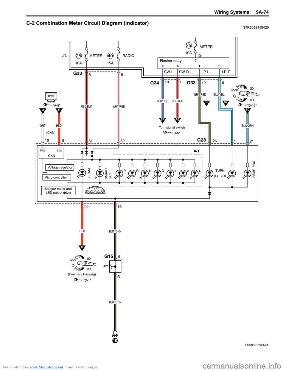
C-2 Combination Meter Circuit Diagram (Indicator)S7RS0B910E020
RADIO
15A40METER
10A25
WHT/RED
32
31 5
Stepper motor and
LED output driver
Voltage regulator
Micro controllerSMART
KEY
G336
RED/BLK
"D-1"
BEAM
REAR FOG
22 A/T
RED
(Dimmer / Passing)
(CAN)
J/B
L23DNRP
16
B
B
BLK /ORN
BLK /ORN
J/C
G15
10
CAN
High Low
R
G28
WHTREDBLU/ORN
"A-8""D-10"RW
10 8
BCM
261
"D-6"
TURN
(R)
GRN/REDBLU/YEL
912G33
1
64
SW-L SW-R LP-L IG
LP-R
Flasher relay
5
7
119G34
10A METER
Turn signal switch
25
RED/BLUBLU/RED
21
GR
RB
BO
BR
(L)
BY
I6RS0C910921-01
Page 1246 of 1496
Downloaded from www.Manualslib.com manuals search engine 9A-75 Wiring Systems:
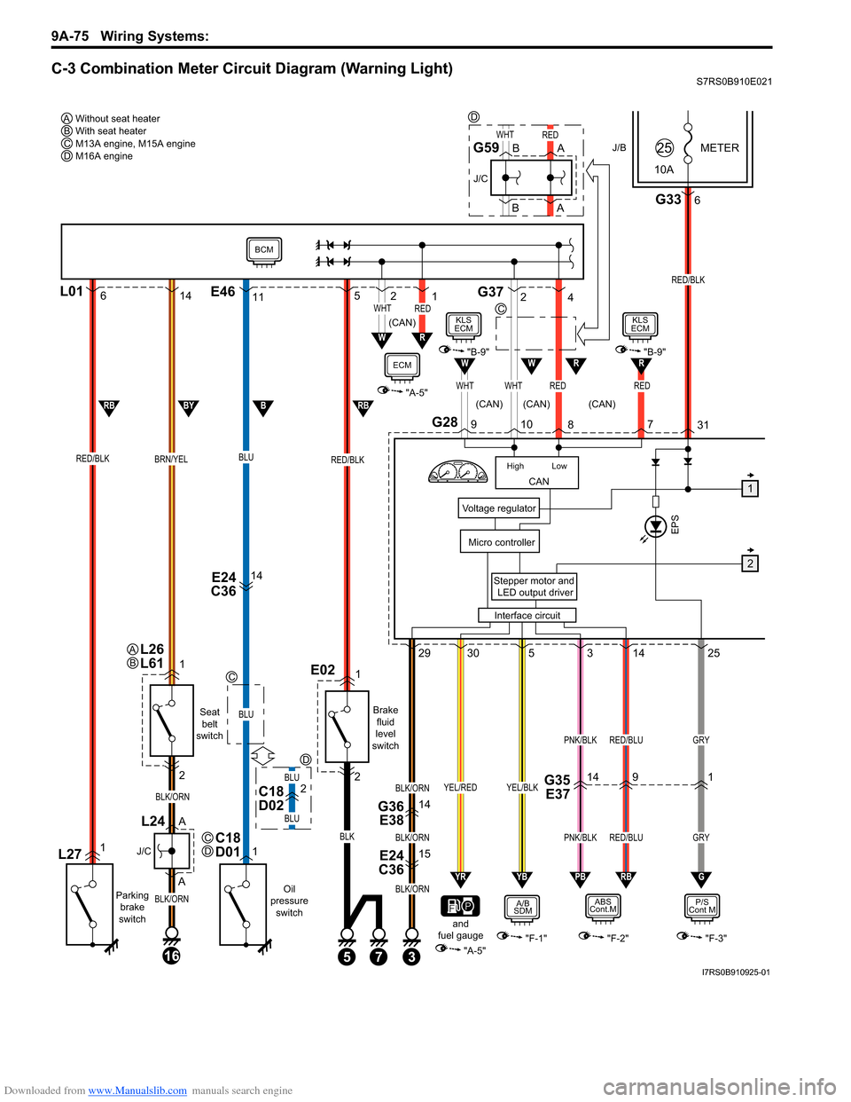
C-3 Combination Meter Circuit Diagram (Warning Light)S7RS0B910E021
J/BMETER
10A25
G2831
3
E24
C3615
G36 E3814
Stepper motor and
LED output driver
Voltage regulator
Interface circuit
Micro controllerEPS
G336
RED/BLK
145293025
PNK/BLKGRY
GRY
RED/BLU
PNK/BLK
BLK/ORN
BLK/ORN
BLK/ORN
RED/BLU
P/S
Cont M
"F-3"
RBPBYBYR
YEL/BLKYEL/RED
A/B
SDM
"F-1""A-5"
ABS
Cont.M
"F-2"
G
CAN
High Low
WHTWHTRED
WHTRED
RED
RW
109 8
6L0114
RED/BLKBRN/YEL
L271
Parking
brake
switch
1
2
A
A
16
BLK/ORN
BLK/ORN
J/C
L24
Seat belt
switch
Oil
pressure switch
E24
C3614
BLU
BLU
1C18
D01
RED/BLK
E021
Brake
fluid
level
switch
and
fuel gauge
2
53
BLK
11 5E46G372
4
RW
W
21WHTRED
"A-5"
1
2
RBBBYRB
7
BCM
ECM"B-9"
KLS
ECM
7
R"B-9"
KLS
ECM
Without seat heater
AWith seat heater
BM13A engine, M15A engine
CM16A engine
D
C
C
C
D
(CAN)
(CAN) (CAN)
(CAN)
L26
L61AB
B
BA
A
J/C
G59
BLU
BLU
D
C18
D022G35 E371419
D
I7RS0B910925-01
Page 1299 of 1496
Downloaded from www.Manualslib.com manuals search engine Instrumentation / Driver Info. / Horn: 9C-4
Schematic and Routing Diagram
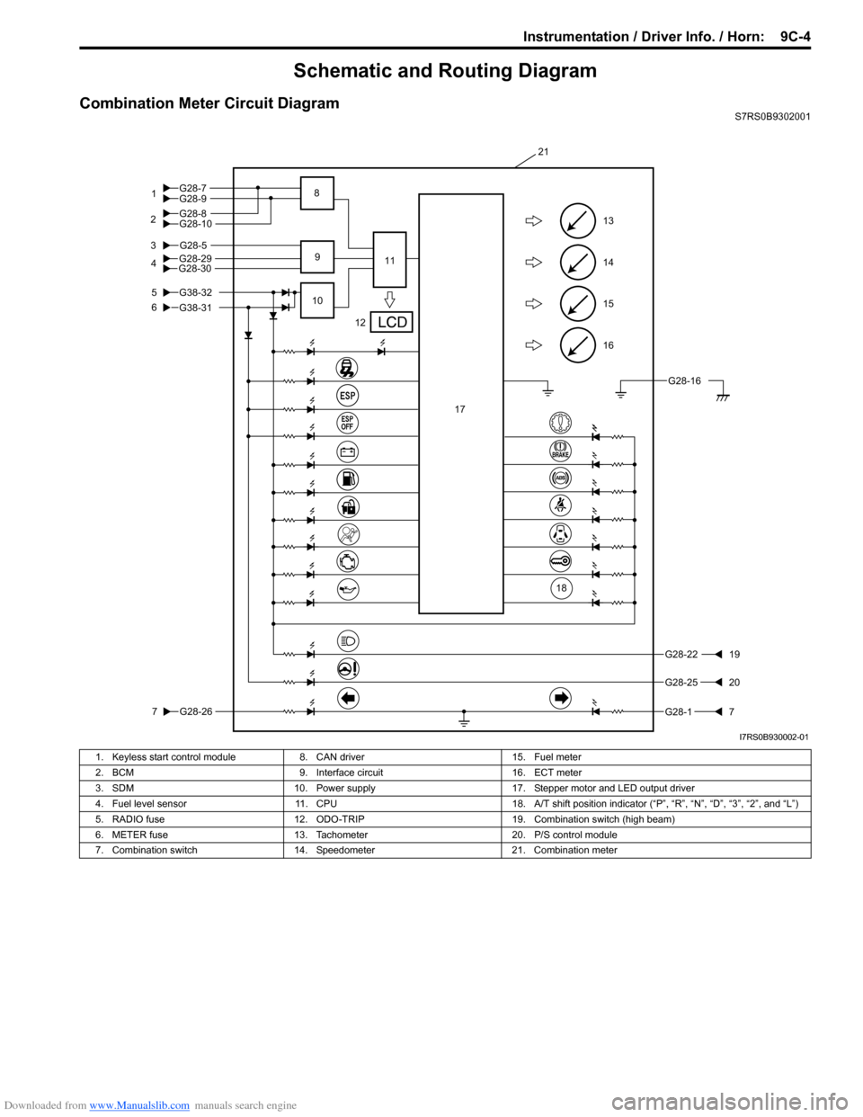
Combination Meter Circuit DiagramS7RS0B9302001
16
15
14
13
G28-5
5
6
3
G28-26
7
G28-2219
G28-2520
G28-17
12
10 11
21
9
17
G28-304G28-29
18
G28-16
G28-9
G28-10G28-8 G28-7
1
2 8
G38-31
G38-32
I7RS0B930002-01
1. Keyless start control module
8. CAN driver 15. Fuel meter
2. BCM 9. Interface circuit 16. ECT meter
3. SDM 10. Power supply 17. Stepper motor and LED output driver
4. Fuel level sensor 11. CPU 18. A/T shift position indicator (“P”, “R”, “N”, “D”, “3”, “2”, and “L”)
5. RADIO fuse 12. ODO-TRIP 19. Combination switch (high beam)
6. METER fuse 13. Tachometer 20. P/S control module
7. Combination switch 14. Speedometer 21. Combination meter
Page 1427 of 1496
Downloaded from www.Manualslib.com manuals search engine Body Electrical Control System: 10B-24
DTC U1073 (No. 1073): Control Module Communication Bus OffS7RS0BA204014
Wiring Diagram
Refer to “DTC U0155 (No. 0155): Lost Communication with Instrument Panel Cluster (IPC) Control Module”.
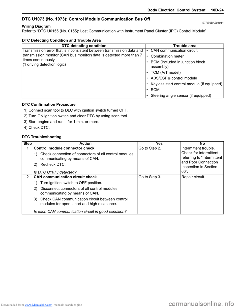
DTC Detecting Condition and Trouble Area
DTC Confirmation Procedure 1) Connect scan tool to DLC with ignition switch turned OFF.
2) Turn ON ignition switch and clear DTC by using scan tool.
3) Start engine and run it for 1 min. or more.
4) Check DTC.
DTC Troubleshooting DTC detecting condition Trouble area
Transmission error that is inconsistent between transmission data and
transmission monitor (CAN bus monitor) data is detected more than 7
times continuously.
(1 driving detection logic) • CAN communication circuit
• Combination meter
• BCM (included in junction block
assembly)
• TCM (A/T model)
• ABS/ESP ® control module
• Keyless start control module (if equipped)
•ECM
• Steering angle sensor (if equipped)
Step Action YesNo
1 Control module connector check
1) Check connection of connectors of all control modules
communicating by means of CAN.
2) Recheck DTC.
Is DTC U1073 detected? Go to Step 2.
Intermittent trouble.
Check for intermittent
referring to “Intermittent
and Poor Connection
Inspection in Section
00”.
2 CAN communication circuit check
1) Turn ignition switch to OFF position.
2) Disconnect connectors of all control modules
communicating by means of CAN.
3) Check CAN communication circuit between control modules for open, short and high resistance.
Is each CAN communication circuit in good condition? Go to Step 3.
Repair circuit.
Page 1432 of 1496
Downloaded from www.Manualslib.com manuals search engine 10B-29 Body Electrical Control System:
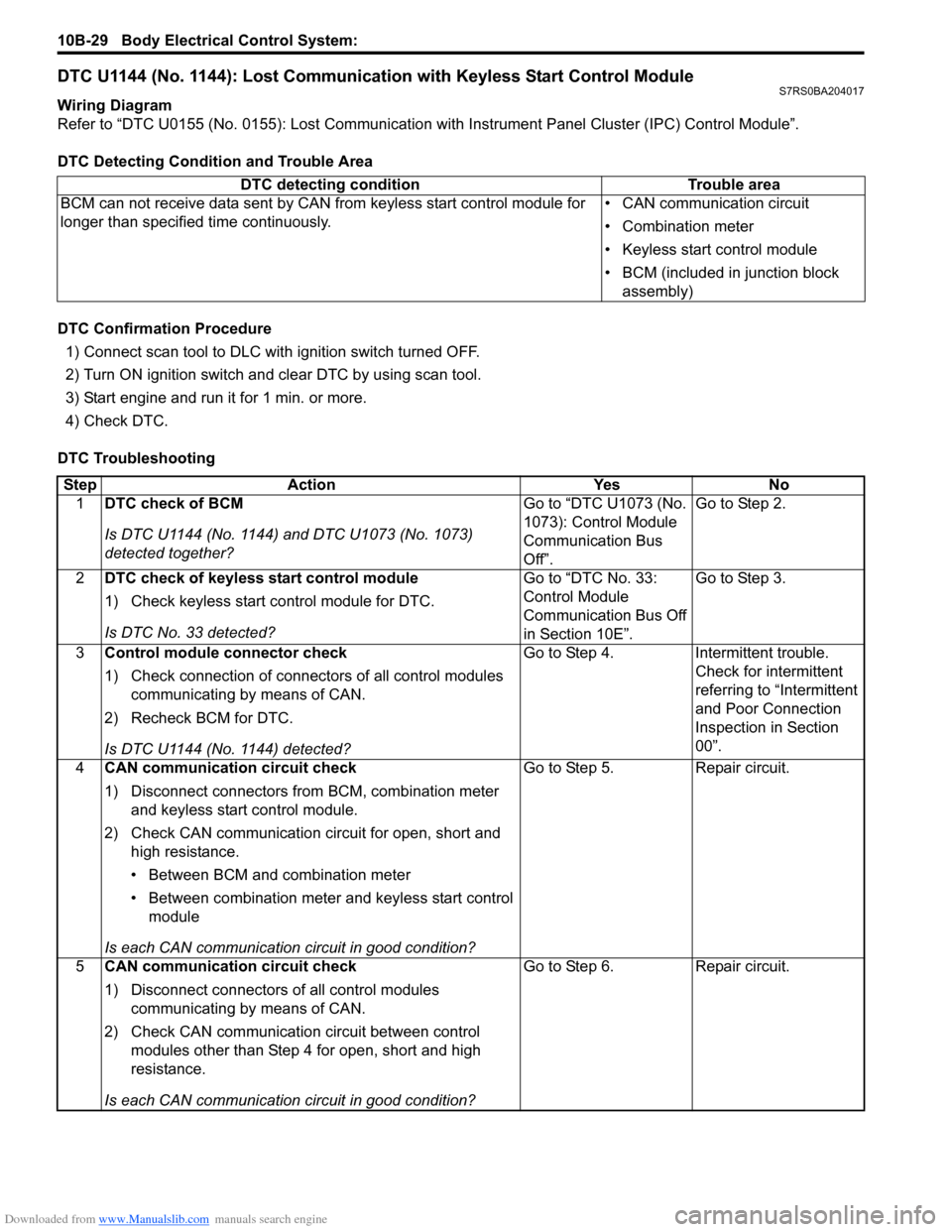
DTC U1144 (No. 1144): Lost Communication with Keyless Start Control ModuleS7RS0BA204017
Wiring Diagram
Refer to “DTC U0155 (No. 0155): Lost Communication with Instrument Panel Cluster (IPC) Control Module”.
DTC Detecting Condition and Trouble Area
DTC Confirmation Procedure 1) Connect scan tool to DLC with ignition switch turned OFF.
2) Turn ON ignition switch and clear DTC by using scan tool.
3) Start engine and run it for 1 min. or more.
4) Check DTC.
DTC Troubleshooting DTC detecting condition Trouble area
BCM can not receive data sent by CAN from keyless start control module for
longer than specified time continuously. • CAN communication circuit
• Combination meter
• Keyless start control module
• BCM (included in junction block
assembly)
Step Action YesNo
1 DTC check of BCM
Is DTC U1144 (No. 1144) and DTC U1073 (No. 1073)
detected together? Go to “DTC U1073 (No.
1073): Control Module
Communication Bus
Off”.Go to Step 2.
2 DTC check of keyless start control module
1) Check keyless start co ntrol module for DTC.
Is DTC No. 33 detected? Go to “DTC No. 33:
Control Module
Communication Bus Off
in Section 10E”.Go to Step 3.
3 Control module connector check
1) Check connection of connectors of all control modules
communicating by means of CAN.
2) Recheck BCM for DTC.
Is DTC U1144 (No. 1144) detected? Go to Step 4.
Intermittent trouble.
Check for intermittent
referring to “Intermittent
and Poor Connection
Inspection in Section
00”.
4 CAN communication circuit check
1) Disconnect connectors from BCM, combination meter
and keyless start control module.
2) Check CAN communication circuit for open, short and high resistance.
• Between BCM and combination meter
• Between combination meter and keyless start control module
Is each CAN communication circuit in good condition? Go to Step 5.
Repair circuit.
5 CAN communication circuit check
1) Disconnect connectors of all control modules
communicating by means of CAN.
2) Check CAN communication circuit between control modules other than Step 4 for open, short and high
resistance.
Is each CAN communication circuit in good condition? Go to Step 6.
Repair circuit.
Page 1447 of 1496
Downloaded from www.Manualslib.com manuals search engine Immobilizer Control System: 10C-4
Schematic and Routing Diagram
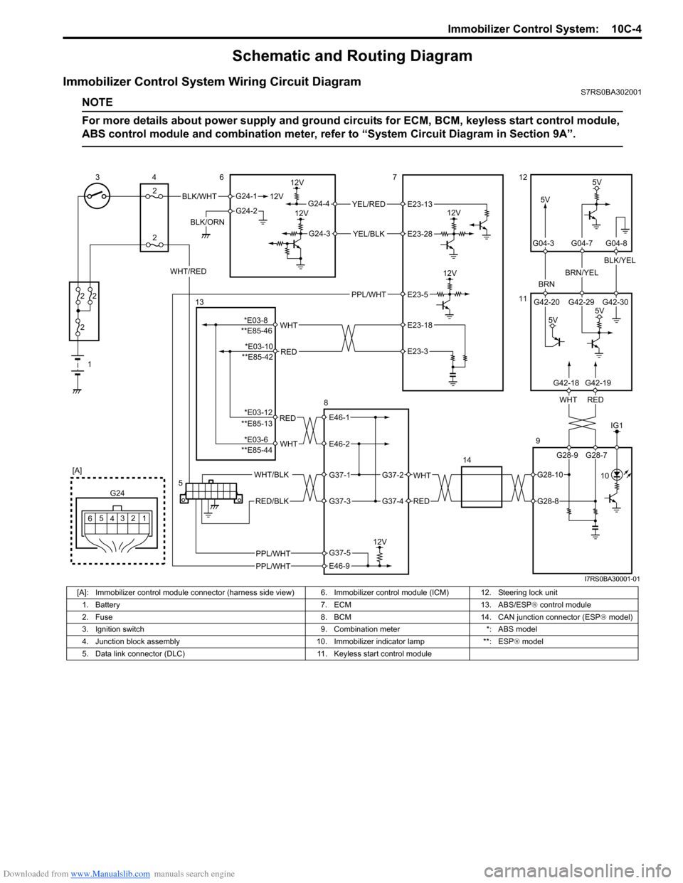
Immobilizer Control System Wiring Circuit DiagramS7RS0BA302001
NOTE
For more details about power supply and ground circuits for ECM, BCM, keyless start control module,
ABS control module and combination meter, refer to “System Ci rcuit Diagram in Section 9A”.
BLK/WHT
BLK/ORN12V
G24-1
G24-2
12V
5V
12V
12VYEL/RED
YEL/BLK
G24-4
G24-3
12V
5V
BRN
BRN/YEL
BLK/YEL
1
2
2 2
2
34
2 6712
11
9
14
12
3
4
G24
[A]
5
6
REDWHT
G42-20 G42-29 G42-30
G04-3 G04-7 G04-8
WHT/RED
5V
5V
5
G28-9 G28-7
G42-18G42-19
E23-13
E23-28
IG1
PPL/WHT 10
PPL/WHT
PPL/WHT
E23-5
RED
WHT**E85-46E23-18
E23-3
RED
WHT
E46-1
E46-2
WHT
RED
G37-2
G37-4
WHT/BLK
RED/BLK
G37-1
G37-3
12V
E46-9
G37-5
13
8
**E85-42
**E85-13
**E85-44
G28-10
G28-8
*E03-8 *E03-10
*E03-12
*E03-6
I7RS0BA30001-01
[A]: Immobilizer control module connector (harness side vi ew) 6. Immobilizer control module (ICM) 12. Steering lock unit
1. Battery 7. ECM 13. ABS/ESP ® control module
2. Fuse 8. BCM 14. CAN junction connector (ESP ® model)
3. Ignition switch 9. Combination meter *: ABS model
4. Junction block assembly 10. Immobilizer indicator lamp **: ESP ® model
5. Data link connector (DLC) 11. Keyless start control module
Page 1450 of 1496
Downloaded from www.Manualslib.com manuals search engine 10C-7 Immobilizer Control System:
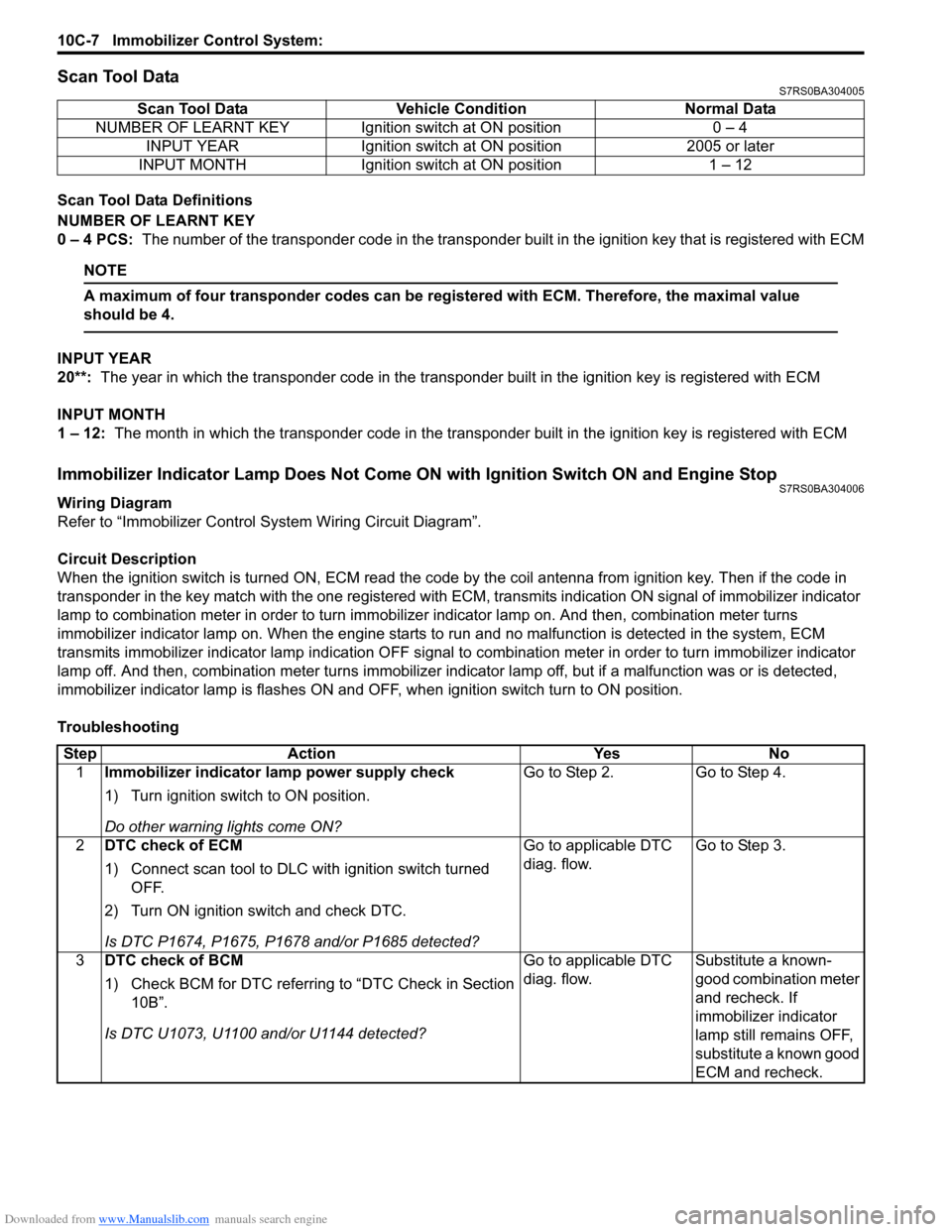
Scan Tool DataS7RS0BA304005
Scan Tool Data Definitions
NUMBER OF LEARNT KEY
0 – 4 PCS: The number of the transponder code in the transponder built in the ignition key that is registered with ECM
NOTE
A maximum of four transponder codes can be registered with ECM. Therefore, the maximal value
should be 4.
INPUT YEAR
20**: The year in which the transponder code in the transpon der built in the ignition key is registered with ECM
INPUT MONTH
1 – 12: The month in which the transponder code in the transpond er built in the ignition key is registered with ECM
Immobilizer Indicator Lamp Does Not Come ON with Ignition Switch ON and Engine StopS7RS0BA304006
Wiring Diagram
Refer to “Immobilizer Control System Wiring Circuit Diagram”.
Circuit Description
When the ignition switch is turned ON, ECM read the code by the coil antenna from ignition key. Then if the code in
transponder in the key match with the one registered with ECM, transmits indication ON signal of immobilizer indicator
lamp to combination meter in order to turn immobilizer indicator lamp on. And then, combination meter turns
immobilizer indicator lamp on. When th e engine starts to run and no malfunction is detected in the system, ECM
transmits immobilizer indi cator lamp indication OFF signal to combination meter in order to turn immobilizer indicator
lamp off. And then, comb ination meter turns immobilizer indicator lamp off, but if a malfunction was or is detected,
immobilizer indicator lamp is flashes ON and OF F, when ignition switch turn to ON position.
Troubleshooting Scan Tool Data Vehicl
e Condition Normal Data
NUMBER OF LEARNT KEY Ignition switch at ON position 0 – 4 INPUT YEAR Ignition switch at ON position 2005 or later
INPUT MONTH Ignition switch at ON position 1 – 12
Step Action YesNo
1 Immobilizer indicator lamp power supply check
1) Turn ignition switch to ON position.
Do other warning lights come ON? Go to Step 2.
Go to Step 4.
2 DTC check of ECM
1) Connect scan tool to DLC with ignition switch turned
OFF.
2) Turn ON ignition switch and check DTC.
Is DTC P1674, P1675, P1678 and/or P1685 detected? Go to applicable DTC
diag. flow.
Go to Step 3.
3 DTC check of BCM
1) Check BCM for DTC referring to “DTC Check in Section
10B”.
Is DTC U1073, U1100 and/or U1144 detected? Go to applicable DTC
diag. flow.
Substitute a known-
good combination meter
and recheck. If
immobilizer indicator
lamp still remains OFF,
substitute a known good
ECM and recheck.
Page 1451 of 1496
Downloaded from www.Manualslib.com manuals search engine Immobilizer Control System: 10C-8
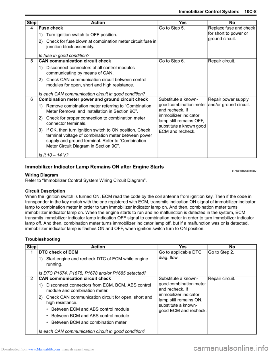
Immobilizer Indicator Lamp Remains ON after Engine StartsS7RS0BA304007
Wiring Diagram
Refer to “Immobilizer Control S ystem Wiring Circuit Diagram”.
Circuit Description
When the ignition switch is turned ON, ECM read the code by the coil antenna from ignition key. Then if the code in
transponder in the key match with the one registered with ECM, transmits indication ON signal of immobilizer indicator
lamp to combination meter in order to turn immobilizer indicator lamp on. And then, combination meter turns
immobilizer indicator lamp on. When th e engine starts to run and no malfunction is detected in the system, ECM
transmits immobilizer indicator lamp indication O FF signal to combination meter in order to turn immobilizer indicator
lamp off. And then, comb ination meter turns immobilizer indicator lamp off, but if a malfunction was or is detected,
immobilizer indicator lamp is flashes ON and OF F, when ignition switch turn to ON position.
Troubleshooting 4
Fuse check
1) Turn ignition switch to OFF position.
2) Check for fuse blown at combination meter circuit fuse in
junction block assembly.
Is fuse in good condition? Go to Step 5. Replace fuse and check
for short to power or
ground circuit.
5 CAN communication circuit check
1) Disconnect connectors of all control modules
communicating by means of CAN.
2) Check CAN communication circuit between control modules for open, short and high resistance.
Is each CAN communication circuit in good condition? Go to Step 6. Repair circuit.
6 Combination meter power and ground circuit check
1) Remove combination meter referring to “Combination
Meter Removal and Installation in Section 9C”.
2) Check for proper connection to combination meter connector terminals.
3) If OK, then turn ignition switch to ON position, Check terminal voltage of combination meter between power
supply and ground terminal. Refer to “Combination
Meter Circuit Diagram in Section 9C”.
Is it 10 – 14 V? Substitute a known-
good combination meter
and recheck. If
immobilizer indicator
lamp still remains OFF,
substitute a known good
ECM and recheck.
Repair power supply
and/or ground circuit.
Step Action Yes No
Step
Action YesNo
1 DTC check of ECM
1) Start engine and recheck DTC of ECM while engine
running.
Is DTC P1674, P1675, P1678 and/or P1685 detected? Go to applicable DTC
diag. flow.
Go to Step 2.
2 CAN communication circuit check
1) Disconnect connectors from ECM, BCM, ABS control
module and combination meter.
2) Check CAN communication circuit for open, short and high resistance.
• Between ECM and ABS control module
• Between BCM and ABS control module
• Between BCM and combination meter
Is each CAN communication circuit in good condition? Substitute a known-
good combination meter
and recheck. If
immobilizer indicator
lamp still remains ON,
substitute a known-
good ECM and recheck.
Repair circuit.
Page 1469 of 1496
Downloaded from www.Manualslib.com manuals search engine Keyless Start System: 10E-7
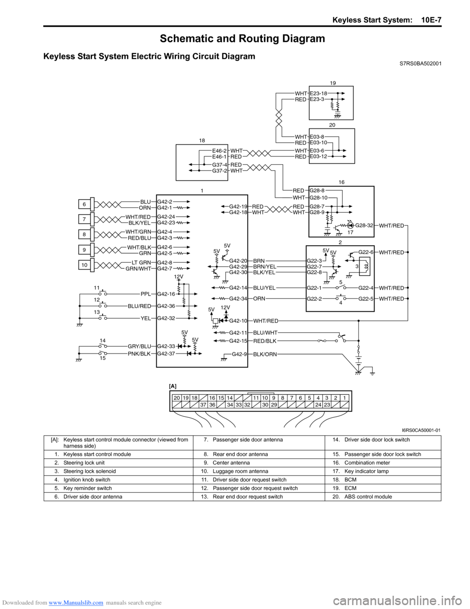
Schematic and Routing Diagram
Keyless Start System Electric Wiring Circuit DiagramS7RS0BA502001
BLK/ORNG42-9
G42-15
G42-14
G42-37G42-33
G42-16
G42-20G42-29G42-30
G42-36
G42-32G42-10
G42-34
G42-11BLU/WHT
WHT/RED
WHT/RED
WHT/RED
PNK/BLKGRY/BLU
BLU/RED
YEL
PPL
RED/BLK
5V5V
5V5V
5V5V
5V
12V
12V
G42-2G42-1BLUORNWHTREDWHTREDG42-18G42-19G28-9G28-7
BLU/YEL
ORN
G42-24G42-23BLK/YELWHT/RED
G42-7GRN/WHTLT G R NG42-8
G42-5G42-6GRNWHT/BLK
G42-4G42-3WHT/GRNRED/BLU
BLK/YELBRN/YELBRNG22-3
G22-1
G22-2G22-5
G22-4
G22-6
G22-7G22-8
WHT/RED
WHT/RED
G37-4
REDWHTREDWHT
G28-10G28-8WHTRED
RED
WHT
G37-2
E46-2
E46-1E03-6
E03-12
G28-32
6
7
8
9
10
11
12
13
14
15 1
18
20
1617
2
4 5 3
1234567891011
141516
36 34 33 32 30 29 24 23
37
181920
[A]
REDWHTE23-18
E23-3
19
REDWHTE03-8
E03-10
I6RS0CA50001-01
[A]: Keyless start control module connector (viewed from
harness side) 7. Passenger side door antenna 14. Driver side door lock switch
1. Keyless start control module 8. Rear end door antenna 15. Passenger side door lock switch
2. Steering lock unit 9. Center antenna 16. Combination meter
3. Steering lock solenoid 10. Luggage room antenna 17. Key indicator lamp
4. Ignition knob switch 11. Driver side door request switch 18. BCM
5. Key reminder switch 12. Passenger side door request switch 19. ECM
6. Driver side door antenna 13. Rear end door request switch 20. ABS control module
Page 1482 of 1496
Downloaded from www.Manualslib.com manuals search engine 10E-20 Keyless Start System:
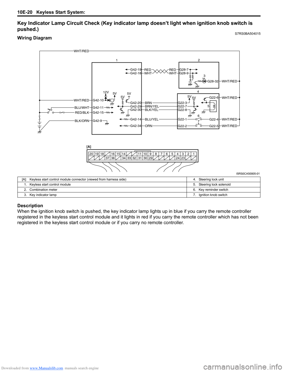
Key Indicator Lamp Circuit Check (Key indicator lamp doesn’t light when ignition knob switch is
pushed.)
S7RS0BA504015
Wiring Diagram
Description
When the ignition knob switch is pushed, the key indicator lamp lights up in blue if you carry the remote controller
registered in the keyless start control module and it lights in red if you carry the remote controller which has not been
registered in the keyless start control module or if you carry no remote controller.
G42-14
G42-20G42-29G42-30
G42-34
WHT/RED
WHT/RED
5V5V
5V5V
BLK/ORNG42-9
G42-15
G42-10
G42-11BLU/WHT
WHT/RED
WHT/RED
RED/BLK
5V
12V
WHTREDWHTREDG42-18G42-19G28-9G28-7
G28-32
BLU/YEL
ORN
BLK/YELBRN/YELBRNG22-3
G22-1
G22-2G22-5
G22-4
G22-6
G22-7G22-8
WHT/RED
WHT/RED
1234567891011
141516
36 34 33 32 31 30 29 24 23
37
181920
1
2
4 5
7 6
[A] 3
I5RS0CA50005-01
[A]: Keyless start control module connector (viewed from harness side)
4. Steering lock unit
1. Keyless start control module 5. Steering lock solenoid
2. Combination meter 6. Key reminder switch
3. Key indicator lamp 7. Ignition knob switch