odometer SUZUKI SWIFT 2006 2.G Service Workshop Manual
[x] Cancel search | Manufacturer: SUZUKI, Model Year: 2006, Model line: SWIFT, Model: SUZUKI SWIFT 2006 2.GPages: 1496, PDF Size: 34.44 MB
Page 31 of 1496
Downloaded from www.Manualslib.com manuals search engine Maintenance and Lubrication: 0B-1
General Information
Maintenance and Lubrication
Precautions
Precautions for Maintenance and LubricationS7RS0B0200001
Air Bag Warning
Refer to “Air Bag Warning in Section 00”.
Scheduled Maintenance
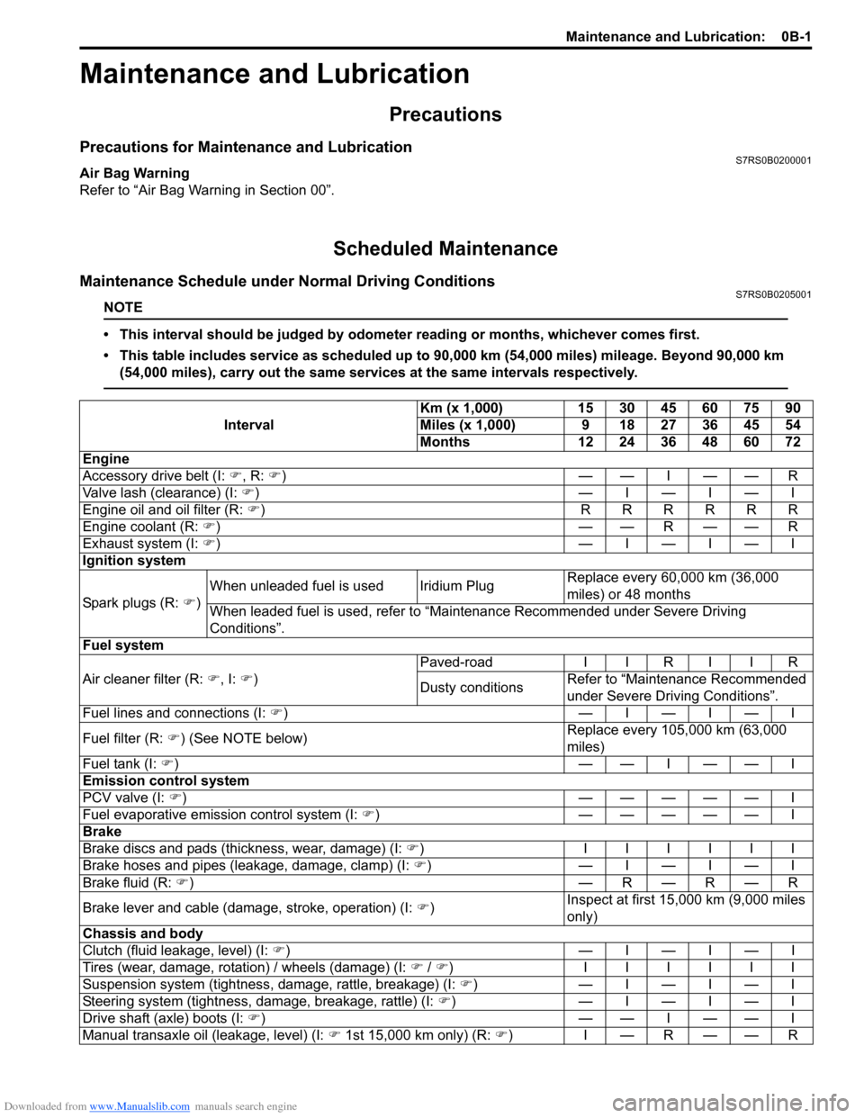
Maintenance Schedule under Normal Driving ConditionsS7RS0B0205001
NOTE
• This interval should be judged by odometer reading or months, whichever comes first.
• This table includes service as scheduled up to 90,000 km (54,000 miles) mileage. Beyond 90,000 km
(54,000 miles), carry out the same services at the same intervals respectively.
Interval Km (x 1,000) 15 30 45 60 75 90
Miles (x 1,000) 9 18 27 36 45 54
Months 12 24 36 48 60 72
Engine
Accessory drive belt (I: �), R: �))——I——R
Valve lash (clearance) (I: �)) —I—I—I
Engine oil and oil filter (R: �)) RRRRRR
Engine coolant (R: �))— —R— — R
Exhaust system (I: �)) —I—I—I
Ignition system
Spark plugs (R: �) )When unleaded fuel is used Iridium Plug
Replace every 60,000 km (36,000
miles) or 48 months
When leaded fuel is used, refer to “Maintenance Recommended under Severe Driving
Conditions”.
Fuel system
Air cleaner filter (R: �), I: �)) Paved-road
I I R I I R
Dusty conditions Refer to “Maintenance Recommended
under Severe Driv
ing Conditions”.
Fuel lines and connections (I: �)) —I—I—I
Fuel filter (R: �)) (See NOTE below) Replace every 105,000 km (63,000
miles)
Fuel tank (I: �))— —I— — I
Emission control system
PCV valve (I: �)) ————— I
Fuel evaporative emission control system (I: �)) ————— I
Brake
Brake discs and pads (thickness, wear, damage) (I: �)) IIIIII
Brake hoses and pipes (leakage, damage, clamp) (I: �)) —I—I—I
Brake fluid (R: �)) —R—R—R
Brake lever and cable (damage, stroke, operation) (I: �)) Inspect at first 15,000 km (9,000 miles
only)
Chassis and body
Clutch (fluid leakage, level) (I: �)) —I—I—I
Tires (wear, damage, rotation) / wheels (damage) (I: �) / �) ) IIIIII
Suspension system (tightness, damage, rattle, breakage) (I: �)) —I—I—I
Steering system (tightness, damage, breakage, rattle) (I: �)) —I—I—I
Drive shaft (axle) boots (I: �))— —I— — I
Manual transaxle oil (leakage, level) (I: �) 1st 15,000 km only) (R: �))I—R——R
Page 43 of 1496
Downloaded from www.Manualslib.com manuals search engine Maintenance and Lubrication: 0B-13
Brake
Foot brake
Check the following:
• that brake pedal has proper travel,
• that brake works properly,
• that it is free from noise,
• that vehicle does not pull to one side when brake is applied.
• and that brake do not drag.
Parking brake
Check that lever has proper travel.
WARNING!
With vehicle parked on a fairly steep slope,
make sure nothing is in the way downhill to
avoid any personal injury or property
damage. Be prepared to apply regular brake
quickly even if vehicle should start to move.
Check to ensure that parking brake is fully effective
when the vehicle is stopped on the safe slope and brake
lever is pulled all the way.
Steering
• Check to ensure that steering wheel is free from instability, or abnormally heavy feeling. • Check that the vehicle does not wander or pull to one
side.
Engine
• Check that engine responds readily at all speeds.
• Check that engine is free from abnormal noise and abnormal vibration.
Body, Wheels and Power Transmitting System
Check that body, wheels and power transmitting system
are free from abnormal noise and abnormal vibration or
any other abnormal condition.
Meters and Gauge
Check that speedometer, odometer, fuel meter,
temperature gauge, etc. are operating accurately.
Lights
Check that all lights operate properly.
Windshield Defroster
Periodically check that ai r comes out from defroster
outlet when operating heater or air conditioning.
Set mode control lever to defroster position and fan
switch lever to “HI” position for this check.
Specifications
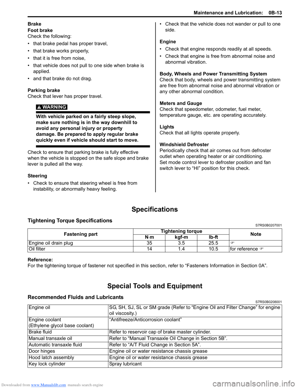
Tightening Torque SpecificationsS7RS0B0207001
Reference:
For the tightening torque of fastener not specified in this section, refer to “Fasteners Information in Section 0A”.
Special Tools and Equipment
Recommended Fluids and LubricantsS7RS0B0208001
Fastening part Tightening torque
Note
N ⋅mkgf-mlb-ft
Engine oil drain plug 35 3.5 25.5 �)
Oil filter 14 1.4 10.5 for reference �)
Engine oilSG, SH, SJ, SL or SM grade (Refer to “Engine Oil and Filter Change” for engine
oil viscosity.)
Engine coolant
(Ethylene glycol base coolant) “Antifreeze/Antico
rrosion coolant”
Brake fluid Refer to reservoir cap of brake master cylinder.
Manual transaxle oil Refer to “Manual Transaxle Oil Change in Section 5B”.
Automatic transaxle fluid Refer to “A/T Fluid Change in Section 5A”.
Door hinges Engine oil or water resistance chassis grease
Hood latch assembly Engine oil or water resistance chassis grease
Key lock cylinder Spray lubricant
Page 55 of 1496
Downloaded from www.Manualslib.com manuals search engine Engine General Information and Diagnosis: 1A-5
Freeze frame data clearance:
The freeze frame data is cleared at the same time as
clearance of DTC.
Non-Euro-OBD
ECM diagnosis troubles which may occur in the area
including the following parts w hen the ignition switch is
ON and the engine is running, and indicates the result by
turning on or flashing malfunction indicator lamp (1).
• Heated oxygen sensor
• ECT sensor
•TP sensor
• APP sensor
• MAF sensor
• IAT sensor
• MAP sensor
• CMP sensor
• CKP sensor
• Knock sensor
• Wheel speed sensor (VSS)
• CPU (Central Processing Unit) of ECM
• Oil control valve
• EGR valve
• EVAP canister purge valve
• Ignition coil
• Starter relay
• Radiator fan relay
• CAN communication
• Barometric pressure sensor
• ECM back up power supply
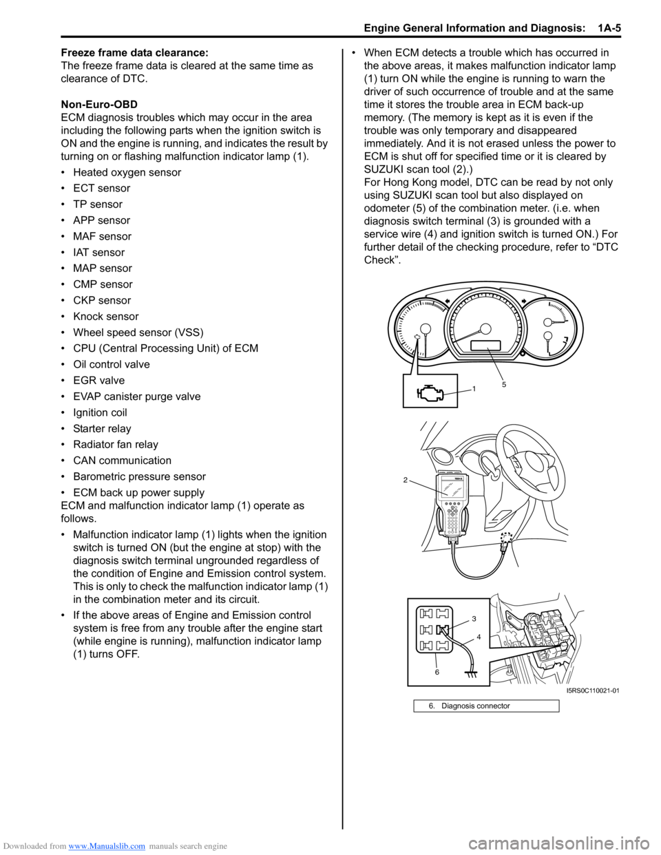
ECM and malfunction indicator lamp (1) operate as
follows.
• Malfunction indicator lamp (1) lights when the ignition switch is turned ON (but t he engine at stop) with the
diagnosis switch terminal ungrounded regardless of
the condition of Engine and Emission control system.
This is only to check the ma lfunction indicator lamp (1)
in the combination meter and its circuit.
• If the above areas of Engine and Emission control system is free from any trouble after the engine start
(while engine is running), malfunction indicator lamp
(1) turns OFF. • When ECM detects a trouble which has occurred in
the above areas, it makes malfunction indicator lamp
(1) turn ON while the engi ne is running to warn the
driver of such occurrence of trouble and at the same
time it stores the trouble area in ECM back-up
memory. (The memory is kept as it is even if the
trouble was only temporary and disappeared
immediately. And it is not erased unless the power to
ECM is shut off for specified time or it is cleared by
SUZUKI scan tool (2).)
For Hong Kong model, DTC can be read by not only
using SUZUKI scan tool but also displayed on
odometer (5) of the combination meter. (i.e. when
diagnosis switch terminal (3) is grounded with a
service wire (4) and ignition switch is turned ON.) For
further detail of the checking procedure, refer to “DTC
Check”.
6. Diagnosis connector
2
1
6 3
5
4
I5RS0C110021-01
Page 63 of 1496
Downloaded from www.Manualslib.com manuals search engine Engine General Information and Diagnosis: 1A-13
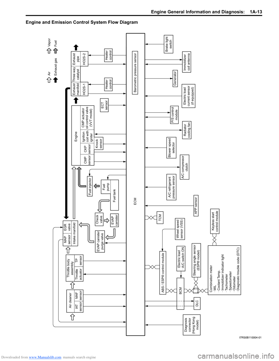
Engine and Emission Control System Flow Diagram
Intake manifold
Exhaust gas AirFuel
Va p o r
EVAP canister purge valve
ECM
Barometric pressure sensor
A/C compressor clutch
Generator
Immobilizer
coil antenna
P/S controlmodule
Brake light switch
Air cleaner
IAT
sensor MAF
sensor
A/C refrigerant
pressure sensor
TP
sensor
Throttle body
assembly
Throttle
actuator
Wheel speed
sensor (VSS)
Steering angle sensor (ESP® model)
ABS / ESP® control module
Blower speed
selector
MAP
sensor EGR
valve
Check valve
EVAP
canisterTCM
Exhaust
manifold Exhaust
pipe
Fuel injector
ECT
sensor
Heater
control
HO2S-1 HO2S-2
Engine
CMP
sensor CKP
sensor
Knock
sensor Ignition
coil with
igniter
Fuel tank
Fuel
pump CMP actuator
oil control valve (VVT model) Three way
catalyst
Heater
control
Radiator
cooling fan
Combination meter
· MIL
· Coolant Temp.
· Immobilizer indicator light
· Tachometer
· Speedometer
· Odometer
· Diagnostic trouble code (DTC)
Keyless start
control module
DLC
· Electric load
· A/C switch ON
BCM
Diagnosis
connector
(Hong Kong model) Electric load
current sensor (if equipped)
APP sensor
I7RS0B110004-01
Page 76 of 1496
Downloaded from www.Manualslib.com manuals search engine 1A-26 Engine General Information and Diagnosis:
DTC CheckS7RS0B1104003
NOTE
• There are two types of OBD system depending on the vehicle specification.
For details, refer to “Precaution on On-
Board Diagnostic (OBD) System”.
• The MIL is turned on when the ECM and/or TCM detect malfunction(s). Each ECM and
TCM stores diagnostic information as the
diagnostic trouble code (DTC) in its
memory and outputs th e DTC to the scan
tool.
Therefore, check both of the ECM and TCM
for any DTC with the SUZUKI scan tool
because the DTC stored in ECM and TCM
is not read and displayed at a time.
However, each of the ECM and TCM needs
not to be checked with the generic scan
tool because the DTC stored in ECM and
TCM is read and displayed at a time.
Using Scan Tool
1) Prepare OBD generic scan tool or SUZUKI scan tool.
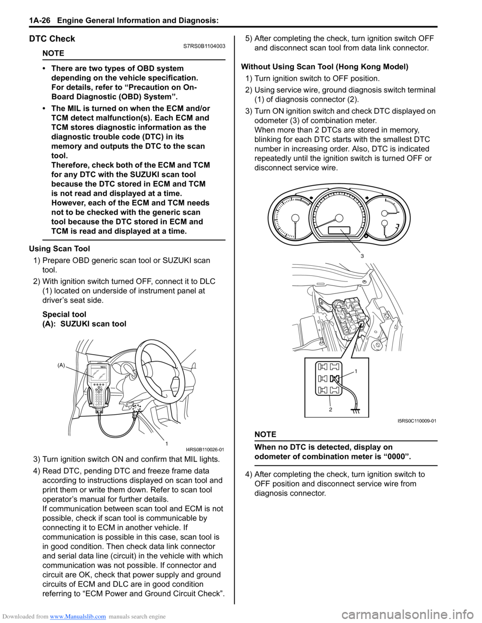
2) With ignition switch turned OFF, connect it to DLC (1) located on underside of instrument panel at
driver’s seat side.
Special tool
(A): SUZUKI scan tool
3) Turn ignition switch ON and confirm that MIL lights.
4) Read DTC, pending DTC and freeze frame data according to instructions displayed on scan tool and
print them or write them down. Refer to scan tool
operator’s manual for further details.
If communication between scan tool and ECM is not
possible, check if scan tool is communicable by
connecting it to ECM in another vehicle. If
communication is possible in this case, scan tool is
in good condition. Then check data link connector
and serial data line (circuit) in the vehicle with which
communication was not possible. If connector and
circuit are OK, check that power supply and ground
circuits of ECM and DLC are in good condition
referring to “ECM Power and Ground Circuit Check”. 5) After completing the check,
turn ignition switch OFF
and disconnect scan tool from data link connector.
Without Using Scan Tool (Hong Kong Model) 1) Turn ignition switch to OFF position.
2) Using service wire, ground diagnosis switch terminal (1) of diagnosis connector (2).
3) Turn ON ignition switch and check DTC displayed on
odometer (3) of combination meter.
When more than 2 DTCs are stored in memory,
blinking for each DTC star ts with the smallest DTC
number in increasing order. Also, DTC is indicated
repeatedly until the ignition switch is turned OFF or
disconnect service wire.
NOTE
When no DTC is detected, display on
odometer of combinatio n meter is “0000”.
4) After completing the check, turn ignition switch to
OFF position and disconnect service wire from
diagnosis connector.
(A)
1
I4RS0B110026-01
21
3
I5RS0C110009-01
Page 469 of 1496
Downloaded from www.Manualslib.com manuals search engine Wheels and Tires: 2D-2
Lower than recommended pressure can cause:
• Tire squeal on turns
• Hard Steering
• Rapid and uneven wear on the edges of the tread
• Tire rim bruises and rupture
• Tire cord breakage
• High tire temperature
• Reduced handling
• High fuel consumption
Replacement Tires
When replacement is necessary, the original equipment
type tire should be used. Refer to the Tire Placard.
Replacement tires should be of the same size, load
range and construction as those originally on the vehicle.
Use of any other size or type tire may affect ride,
handling, speedometer / odometer calibration, vehicle
ground clearance and tire or snow chain clearance to the
body and chassis.
It is recommended that new tires be installed in pairs on
the same axle. If necessary to replace only one tire, it
should be paired with the tire having the most tread, to
equalize braking traction.
WARNING!
Do not mix different types of tires on the
same vehicle such as radial, bias and bias-
belted tires except in emergencies, because
handling may be seriously affected and may
result in loss of control.
The metric term for tire infl ation pressure is the kilo
pascal (kPa). Tire pressures is usually printed in both
kPa and kgf/cm
2 on the “Tire Placard”.
Metric tire gauges are available from tool suppliers.
The chart, shown the table, converts commonly used
inflation pressures from kPa to kgf/cm
2 and psi.
Wheels DescriptionS7RS0B2401002
Wheel Maintenance
Wheel repairs that use welding, heating, or peening are
not approved. All damaged wheels should be replaced.
Replacement Wheels
Wheels must be replaced if they are bent, dented, have
excessive lateral or radial runout, air leak through welds,
have elongated bolt holes, if lug wheel bolts won’t stay
tight, or if they are heavily rusted. Wheels with greater
runout than shown in the following may cause
objectional vibrations.
Replacement wheels must be equivalent to the original
equipment wheels in load capacity, diameter, rim with
offset and mounting configuration. A wheel of improper
size or type may affect wheel and bearing life, brake
cooling, speedometer / odometer calibration, vehicle
ground clearance and tire clearance to body and
chassis.
How to Measure Wheel Runout
To measure the wheel runout, it is necessary to use an
accurate dial indicator. The tire may be on or off the
wheel. The wheel should be installed to the wheel
balancer of the like for proper measurement.
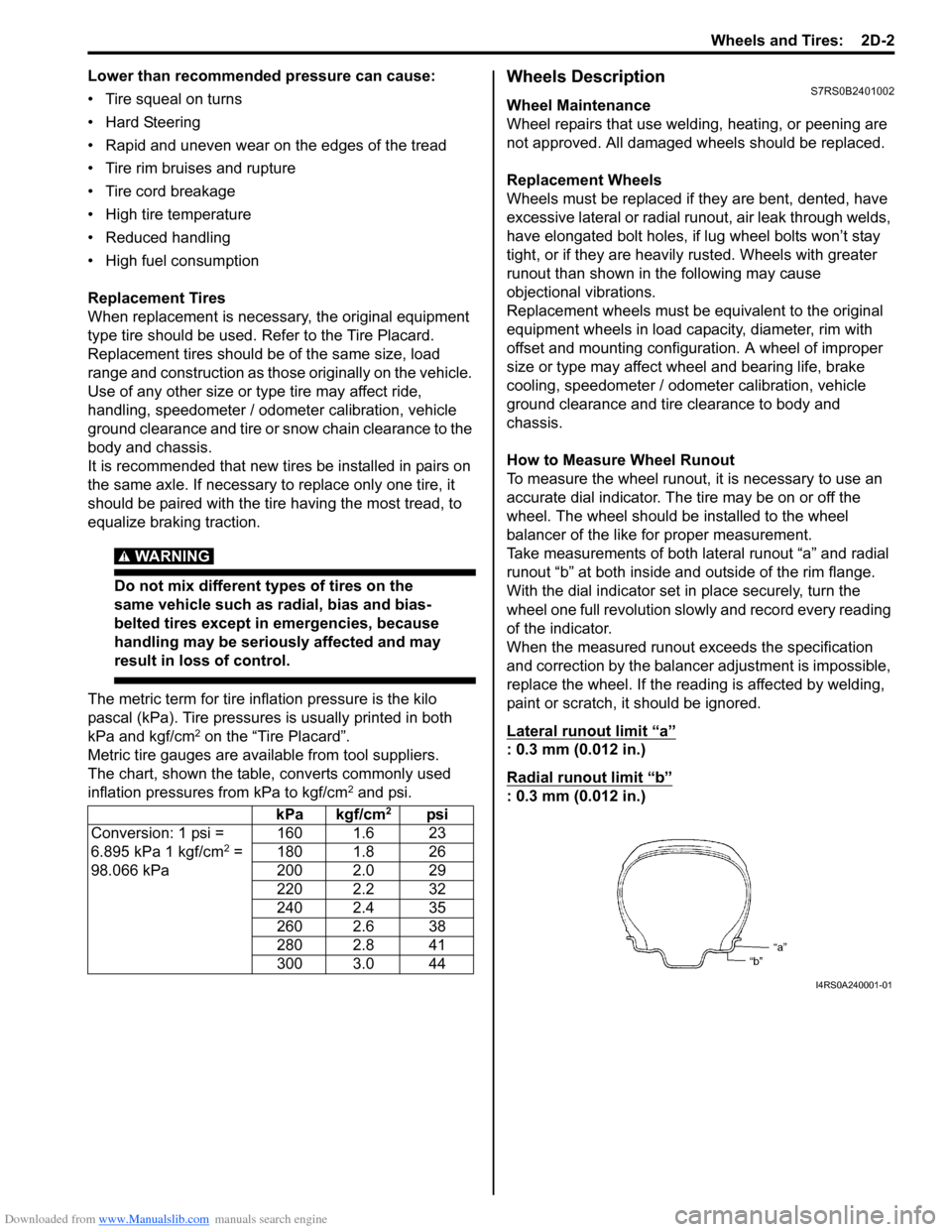
Take measurements of both lateral runout “a” and radial
runout “b” at both inside an d outside of the rim flange.
With the dial indicator set in place securely, turn the
wheel one full revolution slowly and record every reading
of the indicator.
When the measured runout exceeds the specification
and correction by the balancer adjustment is impossible,
replace the wheel. If the reading is affected by welding,
paint or scratch, it should be ignored.
Lateral runout limit “a”
: 0.3 mm (0.012 in.)
Radial runout limit “b”
: 0.3 mm (0.012 in.)
kPa kgf/cm2psi
Conversion: 1 psi =
6.895 kPa 1 kgf/cm
2 =
98.066 kPa 160 1.6 23
180 1.8 26
200 2.0 29
220 2.2 32
240 2.4 35
260 2.6 38
280 2.8 41
300 3.0 44
I4RS0A240001-01
Page 1417 of 1496
Downloaded from www.Manualslib.com manuals search engine Body Electrical Control System: 10B-14
DTC TableS7RS0BA204004
DTC CheckS7RS0BA204005
Using SUZUKI Scan Tool1) Prepare SUZUKI scan tool.
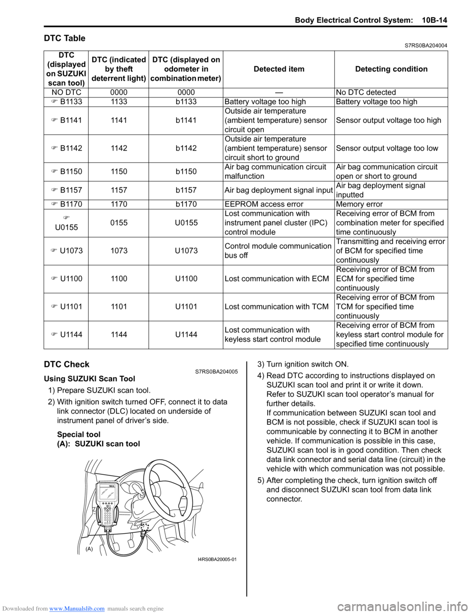
2) With ignition switch turned OFF, connect it to data link connector (DLC) located on underside of
instrument panel of driver’s side.
Special tool
(A): SUZUKI scan tool 3) Turn ignition switch ON.
4) Read DTC according to
instructions displayed on
SUZUKI scan tool and print it or write it down.
Refer to SUZUKI scan tool operator’s manual for
further details.
If communication between SUZUKI scan tool and
BCM is not possible, check if SUZUKI scan tool is
communicable by connecting it to BCM in another
vehicle. If communication is possible in this case,
SUZUKI scan tool is in good condition. Then check
data link connector and serial data line (circuit) in the
vehicle with which communica tion was not possible.
5) After completing the check, turn ignition switch off and disconnect SUZUKI scan tool from data link
connector.
DTC
(displayed
on SUZUKI scan tool) DTC (indicated
by theft
deterrent light) DTC (displayed on
odometer in
combination meter) Detected item Detecting condition
NO DTC 0000 0000 — No DTC detected
�) B1133 1133 b1133 Battery voltage too high Battery voltage too high
�) B1141 1141 b1141 Outside air temperature
(ambient temperature) sensor
circuit openSensor output voltage too high
�) B1142 1142 b1142 Outside air temperature
(ambient temperature) sensor
circuit short to groundSensor output voltage too low
�) B1150 1150 b1150 Air bag communication circuit
malfunctionAir bag communication circuit
open or short to ground
�) B1157 1157 b1157 Air bag deployment signal input Air bag deployment signal
inputted
�) B1170 1170 b1170 EEPROM access error Memory error
�)
U0155 0155 U0155 Lost communication with
instrument panel cluster (IPC)
control moduleReceiving error of BCM from
combination mete
r for specified
time continuously
�) U1073 1073 U1073 Control module communication
bus offTransmitting and receiving error
of BCM for specified time
continuously
�) U1100 1100 U1100 Lost communication with ECM Receiving error of BCM from
ECM for specified time
continuously
�) U1101 1101 U1101 Lost communication with TCM Receiving error of BCM from
TCM for specified time
continuously
�) U1144 1144 U1144 Lost communication with
keyless start control moduleReceiving error of BCM from
keyless start control module for
specified time continuously
(A)
I4RS0BA20005-01
Page 1418 of 1496
Downloaded from www.Manualslib.com manuals search engine 10B-15 Body Electrical Control System:
Without Using SUZUKI Scan Tool1) Turn ignition switch to OFF position.
2) Perform following Steps a) to d) within 10 seconds af ter ignition switch is turned ON and engine stops.
a) Turn headlight switch to “SMALL” position.
b) Turn headlight switch to “OFF” position.
c) Repeat Steps a) and b) 2 times.
d) Press and release driver side door switch 3 times.
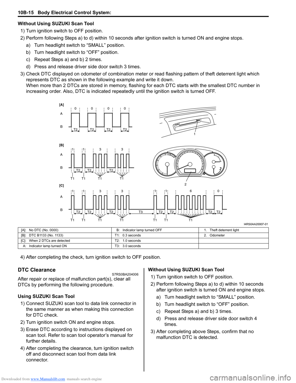
3) Check DTC displayed on odometer of combination meter or read flashing pattern of theft deterrent light which
represents DTC as shown in the following example and write it down.
When more than 2 DTCs are stored in memory, flashing for each DTC starts with the smallest DTC number in
increasing order. Also, DTC is indicated repeatedly until the ignition switch is turned OFF.
4) After completing the check, turn ignition switch to OFF position.
DTC ClearanceS7RS0BA204006
After repair or replace of malfunction part(s), clear all
DTCs by performing the following procedure.
Using SUZUKI Scan Tool 1) Connect SUZUKI scan tool to data link connector in the same manner as when making this connection
for DTC check.
2) Turn ignition switch ON and engine stops.
3) Erase DTC according to instructions displayed on scan tool. Refer to scan tool operator’s manual for
further details.
4) After completing the clear ance, turn ignition switch
off and disconnect scan tool from data link
connector. Without Using SUZUKI Scan Tool
1) Turn ignition switch to OFF position.
2) Perform following Steps a) to d) within 10 seconds after ignition switch is turned ON and engine stops.
a) Turn headlight switch to “SMALL” position.
b) Turn headlight switch to “OFF” position.
c) Repeat Steps a) and b) 3 times.
d) Press and release driver side door switch 4 times.
3) After completing above Steps, confirm that no malfunction DTC is detected.
B A
[B] [A]
[C]
B A B A
3
113
3
113
T2
T1 T1 T1 T1
1
2
T2T2
T2
T1 T1 T1 T1T2T2
0
T2
0
T2
0
T2
0
T2
11 6 0
T1 T1 T1
T2
T3T2T2T2
I4RS0AA20007-01
[A]: No DTC (No. 0000) B: Indicator lamp turned OFF1. Theft deterrent light
[B]: DTC B1133 (No. 1133) T1: 0.3 seconds2. Odometer
[C]: When 2 DTCs are detected T2: 1.0 seconds
A: Indicator lamp tur ned ON T3: 3.0 seconds