Lever SUZUKI SWIFT 2006 2.G Service Owner's Guide
[x] Cancel search | Manufacturer: SUZUKI, Model Year: 2006, Model line: SWIFT, Model: SUZUKI SWIFT 2006 2.GPages: 1496, PDF Size: 34.44 MB
Page 536 of 1496
Downloaded from www.Manualslib.com manuals search engine 4D-1 Parking Brake:
Brakes
Parking Brake
General Description
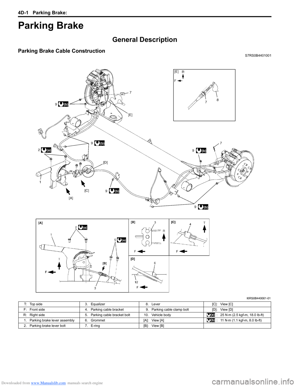
Parking Brake Cable ConstructionS7RS0B4401001
I6RS0B440001-01
T: Top side3. Equalizer8. Lever [C]: View [C]
F: Front side 4. Parking cable bracket9. Parking cable clamp bolt [D]: View [D]
R: Right side 5. Parking cable bracket bolt 10. Vehicle body : 25 N⋅m (2.5 kgf-m, 18.0 lb-ft)
1. Parking brake lever assembly 6. Grommet [A]: View [A]: 11 N⋅m (1.1 kgf-m, 8.0 lb-ft)
2. Parking brake lever bolt 7. E-ring[B]: View [B]
Page 537 of 1496
Downloaded from www.Manualslib.com manuals search engine Parking Brake: 4D-2
Repair Instructions
Parking Brake Inspection and AdjustmentS7RS0B4406001
Inspection
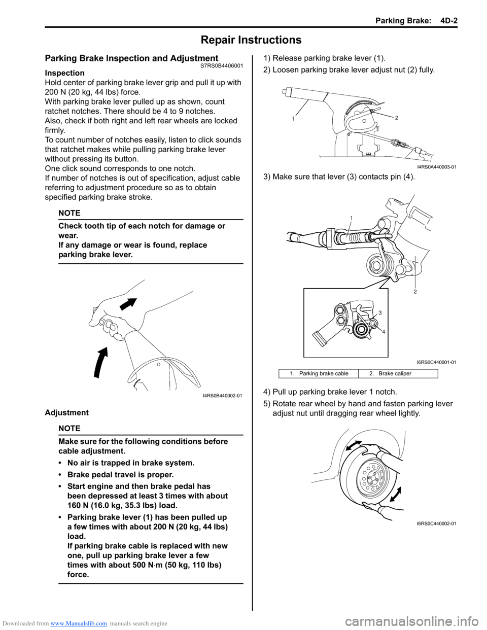
Hold center of parking brake lever grip and pull it up with
200 N (20 kg, 44 lbs) force.
With parking brake lever pulled up as shown, count
ratchet notches. There should be 4 to 9 notches.
Also, check if both right and left rear wheels are locked
firmly.
To count number of notches easily, listen to click sounds
that ratchet makes while pulling parking brake lever
without pressing its button.
One click sound corresponds to one notch.
If number of notches is out of specification, adjust cable
referring to adjustment procedure so as to obtain
specified parking brake stroke.
NOTE
Check tooth tip of each notch for damage or
wear.
If any damage or wear is found, replace
parking brake lever.
Adjustment
NOTE
Make sure for the following conditions before
cable adjustment.
• No air is trapped in brake system.
• Brake pedal travel is proper.
• Start engine and then brake pedal has been depressed at least 3 times with about
160 N (16.0 kg, 35.3 lbs) load.
• Parking brake lever (1) has been pulled up a few times with about 200 N (20 kg, 44 lbs)
load.
If parking brake cable is replaced with new
one, pull up parking brake lever a few
times with about 500 N ⋅m (50 kg, 110 lbs)
force.
1) Release parking brake lever (1).
2) Loosen parking brake lever adjust nut (2) fully.
3) Make sure that lever (3) contacts pin (4).
4) Pull up parking brake lever 1 notch.
5) Rotate rear wheel by hand and fasten parking lever adjust nut until dragging rear wheel lightly.
I4RS0B440002-01
1. Parking brake cable 2. Brake caliper
I4RS0A440003-01
I6RS0C440001-01
I6RS0C440002-01
Page 538 of 1496
Downloaded from www.Manualslib.com manuals search engine 4D-3 Parking Brake:
6) Release parking brake lever and then make sure that there is no drag in rear wheel.
If there is, repeats go to step 2).
7) Make sure that the number of notch is between 4 and 9 when operating parking brake lever.
8) If the number of notch is not between 4 and 9, replace parking brake cable and/or inspect rear
brake caliper.
Parking brake stroke
When lever is pulled up at 200 N (20kg, 44lbs) : 4
to 9 notches
Parking Brake Cable Removal and InstallationS7RS0B4406002
Removal
NOTE
When it is necessary to remove both right
and left parking brake cables, repeat below
steps 2) and 5) on right and left wheels.
1) Hoist vehicle.
2) Remove wheel.
3) Disconnect parking brake cable from equalizer (parking brake lever) and clamps.
4) Disconnect parking brake cable from lever referring to “Rear Disc Brake Caliper Removal and Installation
in Section 4C”.
5) Remove parking brake cable and parking cable bracket.
Installation
Install it by reversing removal procedure, noting the
following points.
• Install clamps properly referring to “Parking Brake Cable Construction”.
• Tighten bolts and nuts to specified torque referring to “Parking Brake Cable Construction”.
Tightening torque
Parking brake lever bolt: 25 N·m (2.5 kgf-m, 18.0
lb-ft)
Parking cable clamp bolt: 11 N·m (1.1 kgf-m, 8.0
lb-ft)
Parking cable bracket bolt: 25 N·m (2.5 kgf-m,
18.0 lb-ft)
• Adjust parking brake cable. Refer to “Parking Brake Inspection and Adjustment”.
• Check brake disc for dragging and brake system for proper performance. Brake test should be performed.
Parking Brake Lever Removal and InstallationS7RS0B4406003
Removal
1) Remove console box.
2) Block vehicle wheels and release parking brake lever.
3) Disconnect lead wire of parking brake switch at coupler.
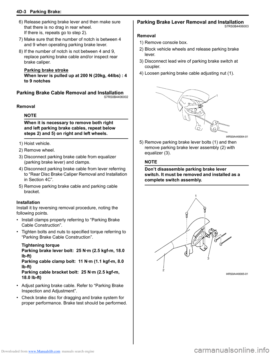
4) Loosen parking brake cable adjusting nut (1).
5) Remove parking brake lever bolts (1) and then remove parking brake lever assembly (2) with
equalizer (3).
NOTE
Don’t disassemble parking brake lever
switch. It must be removed and installed as a
complete switch assembly.
I4RS0A440004-01
I4RS0A440005-01
Page 539 of 1496
Downloaded from www.Manualslib.com manuals search engine Parking Brake: 4D-4
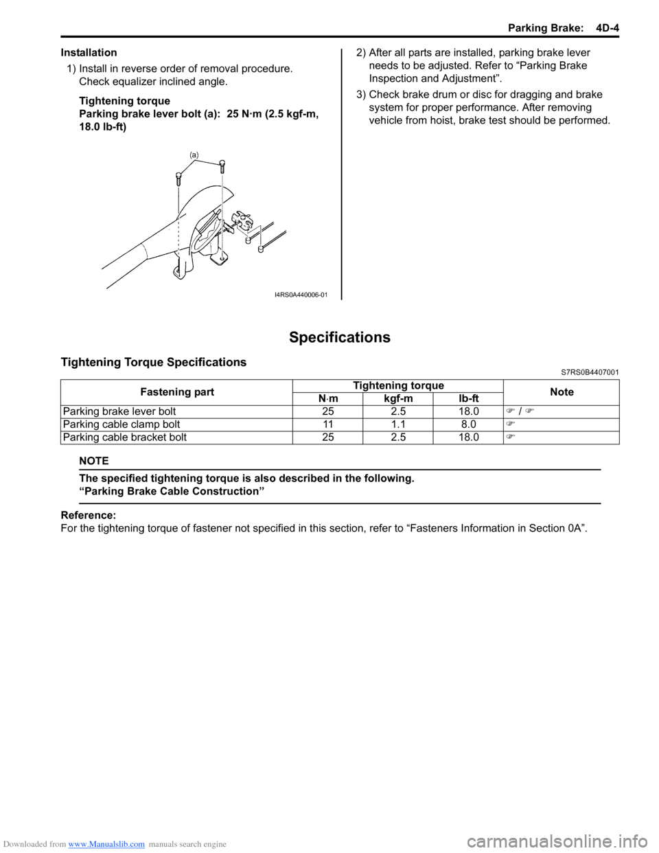
Installation1) Install in reverse order of removal procedure. Check equalizer inclined angle.
Tightening torque
Parking brake lever bolt (a): 25 N·m (2.5 kgf-m,
18.0 lb-ft) 2) After all parts are installed, parking brake lever
needs to be adjusted. Refer to “Parking Brake
Inspection and Adjustment”.
3) Check brake drum or disc for dragging and brake system for proper performance. After removing
vehicle from hoist, brake test should be performed.
Specifications
Tightening Torque SpecificationsS7RS0B4407001
NOTE
The specified tightening torque is also described in the following.
“Parking Brake Cable Construction”
Reference:
For the tightening torque of fastener not specified in this section, refer to “Fasteners Information in Section 0A”.
I4RS0A440006-01
Fastening part Tightening torque
Note
N ⋅mkgf-mlb-ft
Parking brake lever bolt 25 2.5 18.0 �) / �)
Parking cable clamp bolt 11 1.1 8.0 �)
Parking cable bracket bolt 25 2.5 18.0 �)
Page 540 of 1496
Downloaded from www.Manualslib.com manuals search engine 4E-1 ABS:
Brakes
ABS
Precautions
Precautions in Diagnosing TroublesS7RS0B4500001
To ensure that the trouble diagnosis is done accurately
and smoothly, observe the following and follow “ABS
Check”.
• Diagnostic information stored in ABS cont rol module
memory can be cleared as well as checked by using
SUZUKI scan tool. Before us ing scan tool, read its
Operator’s (Instruction) Manual carefully to have good
understanding as to what functions are available and
how to use it.
• If the vehicles was operated in any of the following ways, ABS warning light may light momentarily but
this does not indicate anything abnormal in ABS.
– The vehicle was driven with parking brake pulled.
– The vehicle was driven with brake dragging.
– The vehicle was stuck in mud, sand, etc.
– Wheel spin occurred while driving.
– Wheel(s) was rotated while the vehicle was jacked up.
• Be sure to read “Precautions for Electrical Circuit Service in Section 00” befo re inspection and observe
what is written there.
• Be sure to use the trouble diagnosis procedure as described in “ABS Check”. Failure to follow it may
result in incorrect diagnosis. (Some other diagnosis
trouble code may be stored by mistake in the memory
of ABS control module during inspection.)
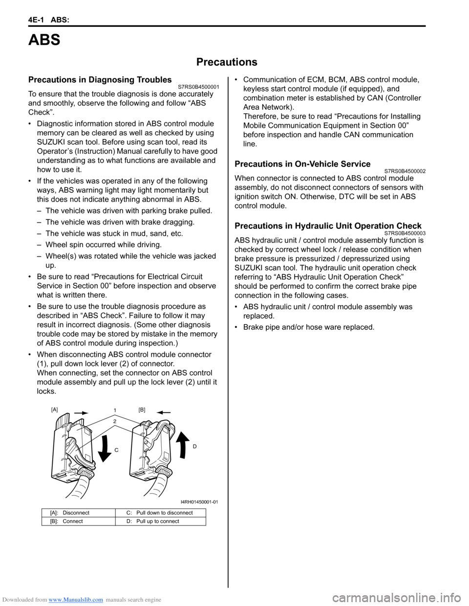
• When disconnecting ABS co ntrol module connector
(1), pull down lock lever (2) of connector.
When connecting, set the connector on ABS control
module assembly and pull up the lock lever (2) until it
locks. • Communication of ECM,
BCM, ABS control module,
keyless start control module (if equipped), and
combination meter is established by CAN (Controller
Area Network).
Therefore, be sure to read “Precautions for Installing
Mobile Communication Equipment in Section 00”
before inspection and handle CAN communication
line.
Precautions in On-Vehicle ServiceS7RS0B4500002
When connector is connected to ABS control module
assembly, do not disconnect connectors of sensors with
ignition switch ON. Otherwise, DTC will be set in ABS
control module.
Precautions in Hydraulic Unit Operation CheckS7RS0B4500003
ABS hydraulic unit / control module assembly function is
checked by correct wheel lock / release condition when
brake pressure is pressurized / depressurized using
SUZUKI scan tool. The hydraulic unit operation check
referring to “ABS Hydraulic Unit Operation Check”
should be performed to confirm the correct brake pipe
connection in the following cases.
• ABS hydraulic unit / cont rol module assembly was
replaced.
• Brake pipe and/or hose ware replaced.
[A]: Disconnect C: Pull down to disconnect
[B]: Connect D: Pull up to connect
21
C D
[A]
[B]
I4RH01450001-01
Page 575 of 1496
Downloaded from www.Manualslib.com manuals search engine Electronic Stability Program: 4F-1
Brakes
Electronic Stability Program
Precautions
Precautions in Diagnosing TroublesS7RS0B4600001
To ensure that the trouble diagnosis is done accurately
and smoothly, observe the following and follow
“Electronic Stability Program System Check”.
• Diagnostic information stored in ESP® control module
memory can be cleared as well as checked by using
SUZUKI scan tool. Before us ing scan tool, read its
Operator’s (Instruction) Manual carefully to have good
understanding as to what functions are available and
how to use it.
• If the vehicles was operated in any of the following ways, ESP ® warning lamp may light momentarily but
this does not indicate anything abnormal in ESP ®.
– The vehicle was driven with parking brake pulled.
– The vehicle was driven with brake dragging.
– The vehicle was stuck in mud, sand, etc.
– Wheel spin occurred while driving.
– Wheel(s) was rotated while the vehicle was jacked up.
• Be sure to use the trouble diagnosis procedure as described in “Electronic Stability Program System
Check”. Failure to follow it may resu lt in incorrect
diagnosis. (Some other diagnosis trouble code may
be stored by mistake in the memory of ESP ® control
module during inspection.)
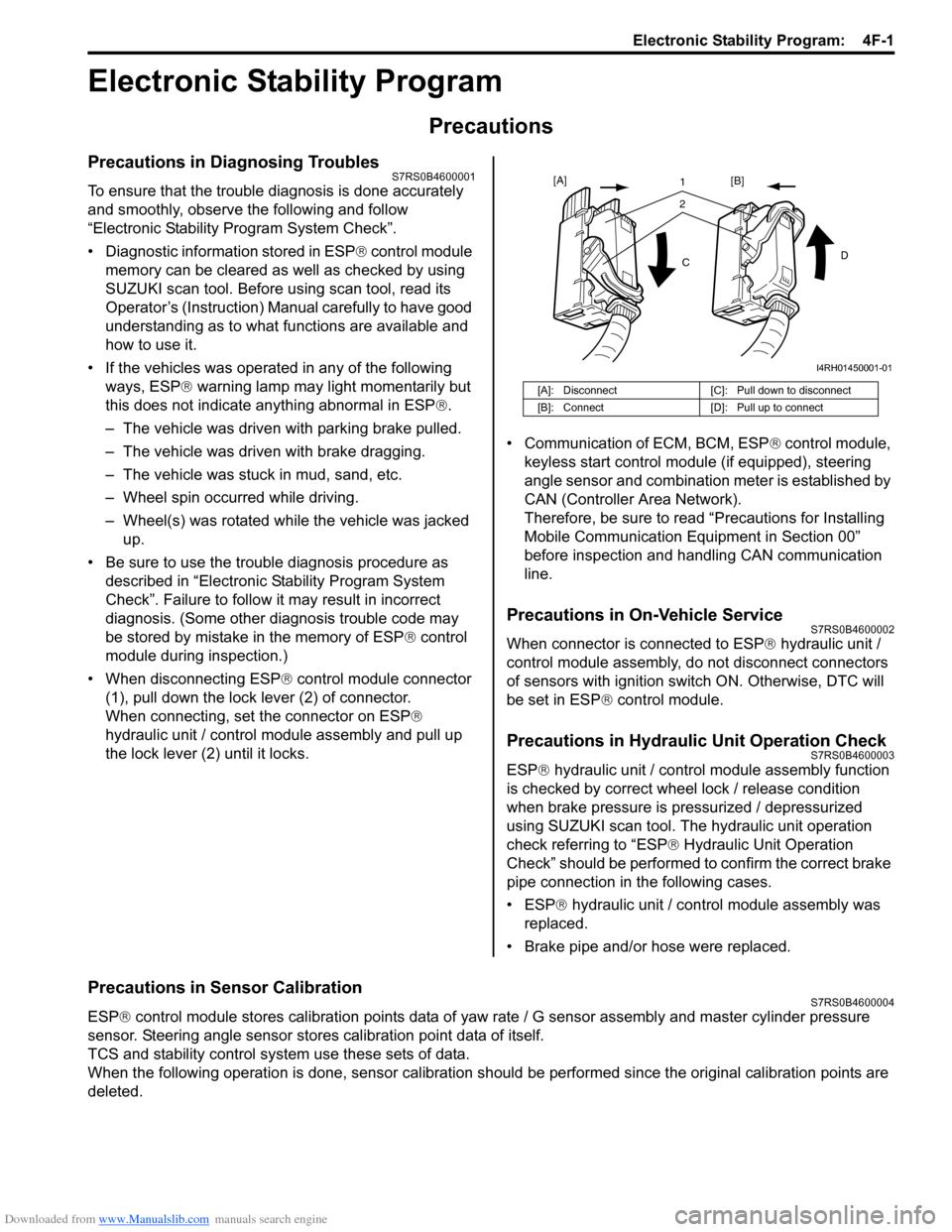
• When disconnecting ESP ® control module connector
(1), pull down the lock lever (2) of connector.
When connecting, set the connector on ESP ®
hydraulic unit / control module assembly and pull up
the lock lever (2) until it locks. • Communication of ECM, BCM, ESP
® control module,
keyless start control module (if equipped), steering
angle sensor and combination meter is established by
CAN (Controller Area Network).
Therefore, be sure to read “Precautions for Installing
Mobile Communication Equipment in Section 00”
before inspection and handling CAN communication
line.
Precautions in On-Vehicle ServiceS7RS0B4600002
When connector is connected to ESP ® hydraulic unit /
control module assembly, do not disconnect connectors
of sensors with ignition switch ON. Otherwise, DTC will
be set in ESP ® control module.
Precautions in Hydraulic Unit Operation CheckS7RS0B4600003
ESP® hydraulic unit / control module assembly function
is checked by correct wheel lock / release condition
when brake pressure is pressurized / depressurized
using SUZUKI scan tool. The hydraulic unit operation
check referring to “ESP ® Hydraulic Unit Operation
Check” should be performed to confirm the correct brake
pipe connection in the following cases.
• ESP® hydraulic unit / contro l module assembly was
replaced.
• Brake pipe and/or hose were replaced.
Precautions in Sensor CalibrationS7RS0B4600004
ESP ® control module stores calibration points data of yaw rate / G sensor assembly and master cylinder pressure
sensor. Steering angle sensor stores calibration point data of itself.
TCS and stability control system use these sets of data.
When the following operation is done, sensor calibration should be performed since the original calibration points are
deleted.
[A]: Disconnect [C]: Pull down to disconnect
[B]: Connect [D]: Pull up to connect
21
C D
[A]
[B]
I4RH01450001-01
Page 642 of 1496

Downloaded from www.Manualslib.com manuals search engine 5-ii Table of Contents
DTC P1878: Torque Converter Clutch Shudder .......................................................... 5A-75
DTC P2762: Torque Converter Clutch (TCC) Pressure Control Sole noid Control Circuit
Range /Performance ....................................... 5A-76
DTC P2763: Torque Converter Clutch Pressure Control Sole noid Control Circuit
High ................................................................. 5A-78
DTC P2764: Torque Converter Clutch Circuit Pressure Control Sole noid Control Circuit
Low ................................................................. 5A-80
Inspection of TCM and Its Circuits .................... 5A-82
TCM Power and Ground Circuit Check ............. 5A-86
Brake Interlock System Inspection .................... 5A-87
Repair Instructions ........... .................................5A-88
Learning Control Initializat ion ............................ 5A-88
A/T Fluid Level Check ....................................... 5A-89
A/T Fluid Change .............................................. 5A-90
Select Lever Components ... .............................. 5A-90
Select Lever Assembly Removal and Installation ....................................................... 5A-90
Select Lever Knob Installa tion........................... 5A-90
Select Lever Inspection .... ................................. 5A-91
“3” Position Switch Inspec tion ........................... 5A-91
Shift Lock Solenoid Inspec tion .......................... 5A-91
Shift Lock Solenoid Replacement ..................... 5A-91
Select Cable Components ................................ 5A-92
Select Cable Removal and Installation ............. 5A-92
Select Cable Adjustment ................................... 5A-93
Key Interlock Cable Removal and Installation... 5A-93
Transmission Range Sensor (Shift Switch) Inspection and Adjustment .............................. 5A-95
Output Shaft Speed Sensor Removal and Installation ....................................................... 5A-96
Output Shaft Speed Sensor Inspection ............. 5A-96
Input Shaft Speed Sensor Removal and Installation ....................................................... 5A-96
Input Shaft Speed Sensor Inspection................ 5A-97
Transmission Fluid Temperature Sensor Removal and Installation ................................. 5A-97
Transmission Fluid Temperature Sensor Inspection ........................................................ 5A-98
Solenoid Valves (Shift Solenoid Valves and Timing Solenoid Valve) Removal and
Installation ....................................................... 5A-98
Solenoid Valves (Shift Solenoid Valves, and Timing Solenoid Valve) Inspection .................. 5A-99
Pressure Control Soleno id Valves (Pressure
Control Solenoid and TCC Pressure Control
Solenoid) Removal and Inst allation .............. 5A-101
Pressure Control Solenoid Valve Inspection ... 5A-101
Transmission Control Module (TCM) Removal and Installation ............................... 5A-102
A/T Relay Inspection ....................................... 5A-103
Differential Side Oil Seal Replacement ........... 5A-103
A/T Fluid Cooler Hoses Replacement ............. 5A-104
Automatic Transaxle Unit Components........... 5A-105
Automatic Transaxle Unit Dismounting and Remounting ................................................... 5A-106
Automatic Transaxle Asse mbly Components . 5A-108 Automatic Transaxle Unit
Disassembly........... 5A-110
Oil Pump Assembly Components ................... 5A-121
Oil Pump Assembly Disassembly and Reassembly .................................................. 5A-122
Oil Pump Assembly Inspection ....................... 5A-122
Direct Clutch Assembly Components.............. 5A-124
Direct Clutch Assembly Preliminary Check ..... 5A-124
Direct Clutch Assembly Disassembly and Reassembly .................................................. 5A-125
Direct Clutch Assembly Inspection.................. 5A-127
Forward and Reverse Clutch Assembly Components .................................................. 5A-128
Forward and Reverse Clutch Assembly Preliminary Check ......................................... 5A-129
Forward and Reverse Clutch Assembly Disassembly and Reassembly ...................... 5A-129
Forward and Reverse Clutch Assembly Inspection ...................................................... 5A-133
2nd Brake Piston Assembly Components ....... 5A-134
2nd Brake Piston Assembly Disassembly and Reassembly .................................................. 5A-134
Transaxle Rear Cover (O/D and 2nd Coast Brake Piston) Assembly Components........... 5A-135
Transaxle Rear Cover (O/D and 2nd Coast Brake Piston) Assembly Disassembly and
Reassembly .................................................. 5A-136
Transaxle Rear Cover (O/D and 2nd Coast Brake Piston) Assembly Inspection............... 5A-137
Countershaft Assembly Co mponents.............. 5A-138
Countershaft Assembly Disassembly and Reassembly .................................................. 5A-138
Valve Body Assembly Components ................ 5A-139
Valve Body Assembly Disassembly and Reassembly .................................................. 5A-140
Differential Assembly Components ................. 5A-141
Differential Assembly Disassembly and Reassembly .................................................. 5A-142
Differential Assembly Inspection ..................... 5A-143
Torque Converter Housing Disassembly and Reassembly .................................................. 5A-144
Transaxle Case Disassembly and Reassembly .................................................. 5A-146
Automatic Transaxle Unit Inspection and Adjus
tment .................................................... 5A-147
Automatic Transaxle Unit Assembly ............... 5A-150
Specifications .................. .................................5A-167
Tightening Torque Specifications .................... 5A-167
Special Tools and Equipmen t .........................5A-168
Recommended Service Material ..................... 5A-168
Special Tool .................................................... 5A-168
Manual Transmission/Tr ansaxle ............ 5B-1
General Description .............................................5B-1
Manual Transaxle Construction and Servicing .... 5B-1
Diagnostic Information and Procedures ............5B-3 Manual Transaxle Symptom Diagnosis............... 5B-3
Repair Instructions ............ ..................................5B-3
Manual Transaxle Oil Change............................. 5B-3
Differential Side Oil Seal Replacement ............... 5B-4
Page 643 of 1496
Downloaded from www.Manualslib.com manuals search engine Table of Contents 5-iii
Gear Shift Control Lever and Cable Components...................................................... 5B-5
Gear Shift Control Le ver and Cable Removal
and Installation .................................................. 5B-6
Gear Select Control Cable Adjustment ............... 5B-6
Back Up Light Switch Removal and Installation ......................................................... 5B-7
Back Up Light Switch Inspection ......................... 5B-7
Manual Transaxle Unit Components ................... 5B-8
Manual Transaxle Unit Dismounting and Remounting....................................................... 5B-9
Gear Shift and Sele ct Shaft Assembly
Components.................................................... 5B-11
Gear Shift and Sele ct Shaft Assembly
Removal and Installation................................. 5B-11
Gear Shift and Select Shaft Disassembly and Assembly ........................................................ 5B-12
Manual Transaxle Assembly Components........ 5B-13
Fifth Gear Disassembly and Assembly ............. 5B-14
Manual Transaxle Assembly Disassembly and Reassembly ............................................. 5B-16
Transaxle Right Case Disassembly and Assembly ........................................................ 5B-23
Transaxle Left Case Disassembly and Assembly ........................................................ 5B-24
Input Shaft and Countershaft Components....... 5B-25
Input Shaft Assembly Disassembly and Reassembly .................................................... 5B-26
Countershaft Assembly Disassembly and Reassembly .................................................... 5B-28
Synchronizer Parts Inspec tion .......................... 5B-31
Gear Shift Shaft Components ........................... 5B-31
5th and Reverse Gear Shift Shafts Disassembly and Assembly ............................ 5B-32
Gear Shift Shaft and Fork Inspection ................ 5B-32
Differential Components ................................... 5B-33
Differential Disassembly and Assembly ............ 5B-33
Specifications ..................................................... 5B-35
Tightening Torque Specifications ...................... 5B-35
Special Tools and Equipmen t ........................... 5B-36
Recommended Service Material ....................... 5B-36 Special Tool ...................................................... 5B-36
Clutch ................
.............................. ......... 5C-1
General Description .............................................5C-1
Clutch Construction .............................................5C-1
Diagnostic Information and Procedures ............5C-2 Clutch System Symptom Diagnosis ....................5C-2
Repair Instructions ........... ...................................5C-2
Clutch Pedal Inspection ......................................5C-2
Clutch Fluid Level Inspection ..............................5C-3
Air Bleeding of Clutch System.............................5C-3
Clutch Pedal Position (CPP) Switch Removal and Installation ..................................................5C-4
Clutch Pedal Position (CPP) Switch Inspection and Adjustment ................................5C-5
Clutch Fluid Pipe and Hose Components ...........5C-5
Clutch Fluid Pipe Removal and Installation.........5C-6
Clutch Fluid Pipe Inspection................................5C-6
Clutch Master Cylinder Removal and Installation .........................................................5C-6
Clutch Operating Cylinder Removal and Installation .........................................................5C-7
Clutch Operating Cylinder Inspection..................5C-7
Clutch Pedal and Clutch Pedal Bracket Components ......................................................5C-7
Clutch Cover, Clutch Disc and Flywheel Components ......................................................5C-8
Clutch Cover, Clutch Disc and Flywheel Removal and Installation ...................................5C-8
Clutch Cover, Clutch Disc and Flywheel Inspection ........................................................5C-10
Clutch Release Syst em Removal and
Installation .......................................................5C-11
Clutch Release System Inspection ...................5C-13
Specifications .................... .................................5C-13
Tightening Torque Specifications ......................5C-13
Special Tools and Equipmen t ...........................5C-14
Recommended Service Material .......................5C-14
Special Tool ......................................................5C-14
Page 652 of 1496
Downloaded from www.Manualslib.com manuals search engine 5A-8 Automatic Transmission/Transaxle:
Brake Interlock System ConstructionS7RS0B5101004
Shift Lock Solenoid Control
This system consists of shift lock solenoid control
system and interlock cable control system.
The shift lock solenoid cont rol system is so designed
that the select lever can not be shifted from “P” range
position unless ignition switch is turned to “ON” or “ACC”
position and the brake pedal is depressed.
And interlock cable control system is so designed that
select lever cannot be shifted from “P” range position
unless ignition switch is turned to “ACC” or “ON”
position. Also, ignition key cannot be pulled out of key
slot unless select le ver is in “P” range.
Shift Lock Solenoid Manual Release
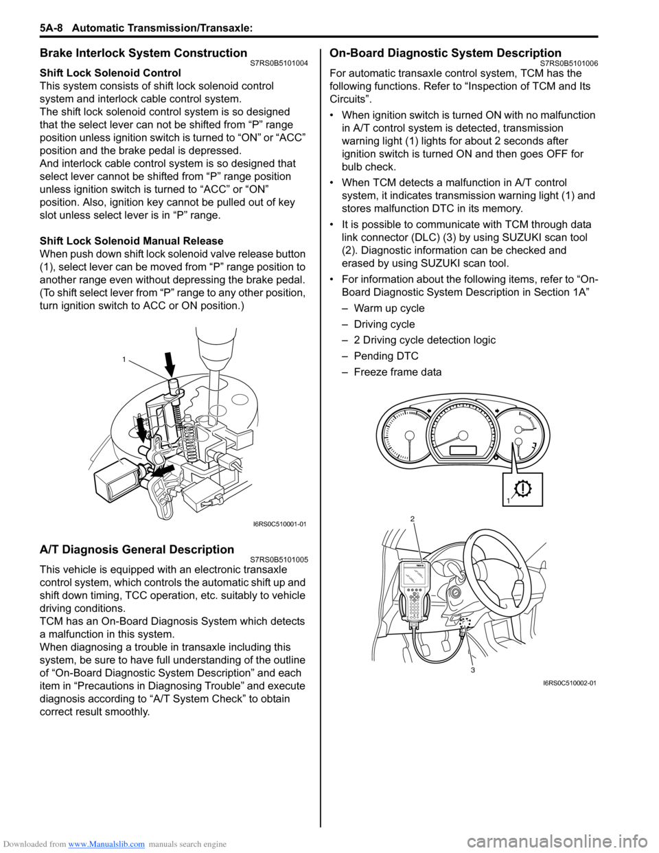
When push down shift lock solenoid valve release button
(1), select lever can be moved from “P” range position to
another range even without depressing the brake pedal.
(To shift select lever from “P” range to any other position,
turn ignition switch to ACC or ON position.)
A/T Diagnosis General DescriptionS7RS0B5101005
This vehicle is equipped with an electronic transaxle
control system, which controls the automatic shift up and
shift down timing, TCC operation, etc. suitably to vehicle
driving conditions.
TCM has an On-Board Diagnosis System which detects
a malfunction in this system.
When diagnosing a trouble in transaxle including this
system, be sure to have full understanding of the outline
of “On-Board Diagnostic System Description” and each
item in “Precautions in Diagnosing Trouble” and execute
diagnosis according to “A/T System Check” to obtain
correct result smoothly.
On-Board Diagnostic System DescriptionS7RS0B5101006
For automatic transaxle co ntrol system, TCM has the
following functions. Refer to “Inspection of TCM and Its
Circuits”.
• When ignition switch is turned ON with no malfunction in A/T control system is detected, transmission
warning light (1) lights for about 2 seconds after
ignition switch is turned ON and then goes OFF for
bulb check.
• When TCM detects a malfunction in A/T control system, it indicates transmission warning light (1) and
stores malfunction DTC in its memory.
• It is possible to communicate with TCM through data link connector (DLC) (3) by using SUZUKI scan tool
(2). Diagnostic information can be checked and
erased by using SUZUKI scan tool.
• For information about the following items, refer to “On- Board Diagnostic System De scription in Section 1A”
– Warm up cycle
– Driving cycle
– 2 Driving cycle detection logic
– Pending DTC
– Freeze frame data
1
I6RS0C510001-01
3
2
1
I6RS0C510002-01
Page 653 of 1496
Downloaded from www.Manualslib.com manuals search engine Automatic Transmission/Transaxle: 5A-9
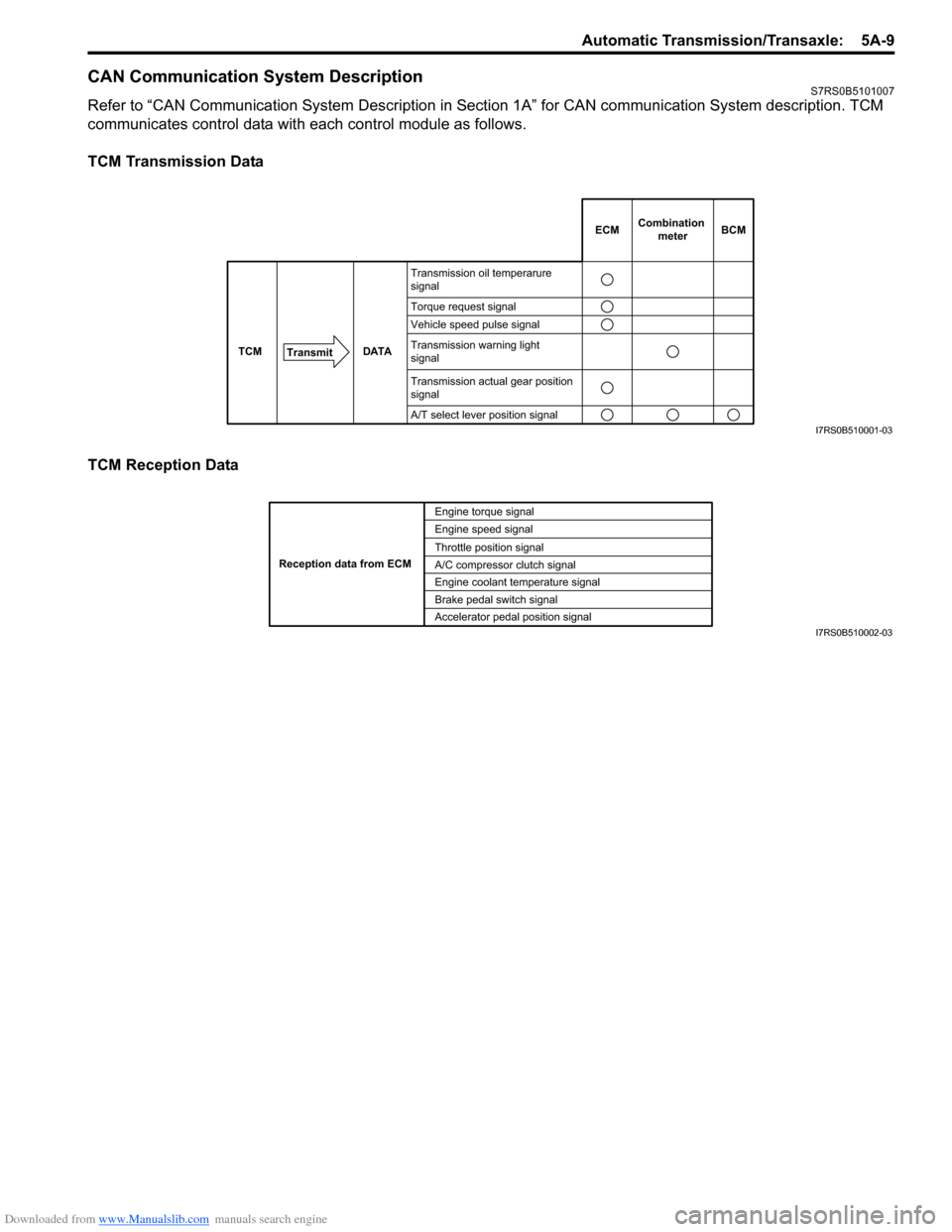
CAN Communication System DescriptionS7RS0B5101007
Refer to “CAN Communication System Description in Section 1A” for CAN communication System description. TCM
communicates control data with each control module as follows.
TCM Transmission Data
TCM Reception Data
DATA
TCM
Transmit
Transmission oil temperarure
signal
Torque request signal
Vehicle speed pulse signal
Transmission warning light
signal
Transmission actual gear position
signal
A/T select lever position signal
ECMCombination
meterBCM
I7RS0B510001-03
Engine torque signal
Engine speed signal
Throttle position signal
A/C compressor clutch signal
Engine coolant temperature signal
Brake pedal switch signal
Reception data from ECM
Accelerator pedal position signalI7RS0B510002-03