Air flow SUZUKI SWIFT 2006 2.G Service Service Manual
[x] Cancel search | Manufacturer: SUZUKI, Model Year: 2006, Model line: SWIFT, Model: SUZUKI SWIFT 2006 2.GPages: 1496, PDF Size: 34.44 MB
Page 659 of 1496
Downloaded from www.Manualslib.com manuals search engine Automatic Transmission/Transaxle: 5A-15
Diagnostic Information and Procedures
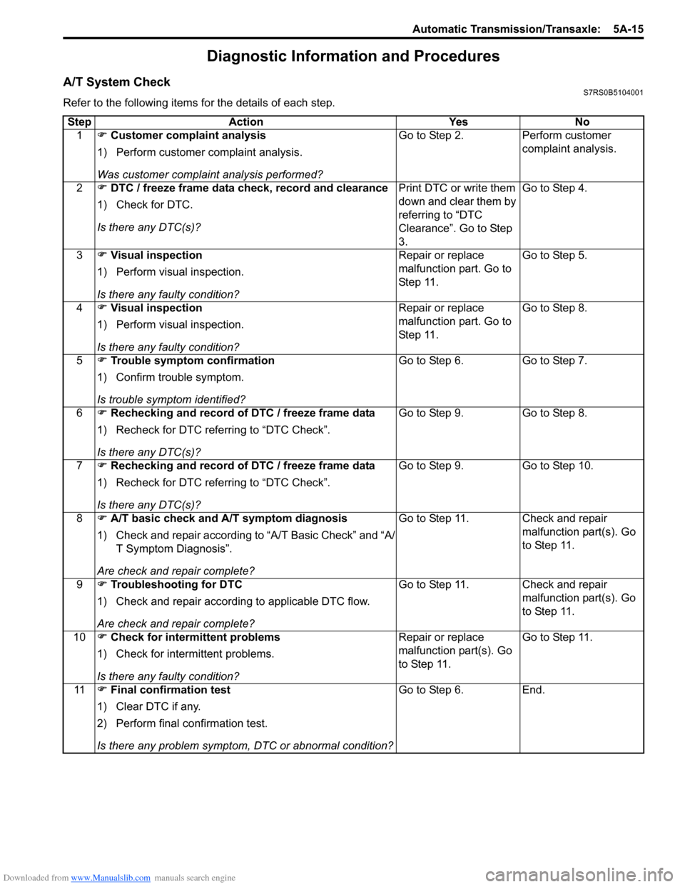
A/T System CheckS7RS0B5104001
Refer to the following items for the details of each step.Step Action Yes No 1 �) Customer complaint analysis
1) Perform customer complaint analysis.
Was customer complaint analysis performed? Go to Step 2. Perform customer
complaint analysis.
2 �) DTC / freeze frame data check, record and clearance
1) Check for DTC.
Is there any DTC(s)? Print DTC or write them
down and clear them by
referring to “DTC
Clearance”. Go to Step
3.Go to Step 4.
3 �) Visual inspection
1) Perform visual inspection.
Is there any faulty condition? Repair or replace
malfunction part. Go to
St ep 11 .
Go to Step 5.
4 �) Visual inspection
1) Perform visual inspection.
Is there any faulty condition? Repair or replace
malfunction part. Go to
St ep 11 .
Go to Step 8.
5 �) Trouble symptom confirmation
1) Confirm trouble symptom.
Is trouble symptom identified? Go to Step 6.
Go to Step 7.
6 �) Rechecking and record of DTC / freeze frame data
1) Recheck for DTC referring to “DTC Check”.
Is there any DTC(s)? Go to Step 9.
Go to Step 8.
7 �) Rechecking and record of DTC / freeze frame data
1) Recheck for DTC referring to “DTC Check”.
Is there any DTC(s)? Go to Step 9.
Go to Step 10.
8 �) A/T basic check and A/T symptom diagnosis
1) Check and repair according to “A/T Basic Check” and “A/
T Symptom Diagnosis”.
Are check and repair complete? Go to Step 11. Check and repair
malfunction part(s). Go
to Step 11.
9 �) Troubleshooting for DTC
1) Check and repair according to applicable DTC flow.
Are check and repair complete? Go to Step 11. Check and repair
malfunction part(s). Go
to Step 11.
10 �) Check for intermittent problems
1) Check for interm ittent problems.
Is there any faulty condition? Repair or replace
malfunction part(s). Go
to Step 11.
Go to Step 11.
11 �) Final confirmation test
1) Clear DTC if any.
2) Perform final confirmation test.
Is there any problem symptom, DTC or abnormal condition? Go to Step 6.
End.
Page 661 of 1496
Downloaded from www.Manualslib.com manuals search engine Automatic Transmission/Transaxle: 5A-17
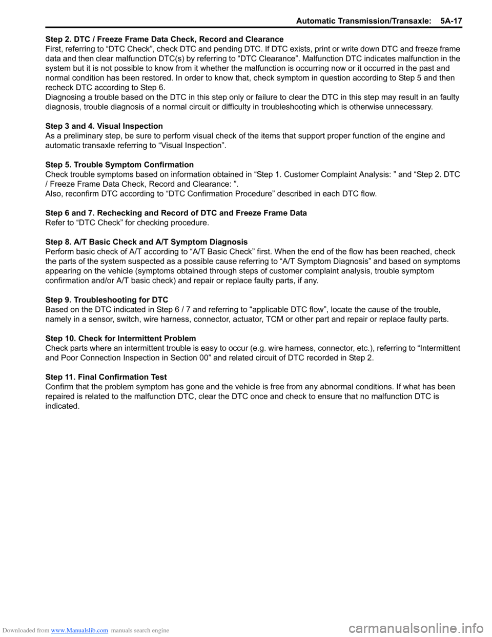
Step 2. DTC / Freeze Frame Data Check, Record and Clearance
First, referring to “DTC Check”, check DTC and pending DTC. If DTC exists, print or write down DTC and freeze frame
data and then clear malfunction DTC(s) by referring to “DTC Clearance”. Malfunction DTC indicates malfunction in the
system but it is not possible to know from it whether the malfunction is occurring now or it occurred in the past and
normal condition has been restored. In order to know that, check symptom in question according to Step 5 and then
recheck DTC according to Step 6.
Diagnosing a trouble based on the DTC in this step only or fa ilure to clear the DTC in this step may result in an faulty
diagnosis, trouble diagnosis of a normal circuit or difficulty in troubleshooting which is otherwise unnecessary.
Step 3 and 4. Visual Inspection
As a preliminary step, be sure to perform visual check of the items that support proper function of the engine and
automatic transaxle referring to “Visual Inspection”.
Step 5. Trouble Symptom Confirmation
Check trouble symptoms based on information obtained in “Step 1. Customer Complaint Analysis: ” and “Step 2. DTC
/ Freeze Frame Data Check, Record and Clearance: ”.
Also, reconfirm DTC according to “DTC Confirmation Procedure” described in each DTC flow.
Step 6 and 7. Rechecking and Record of DTC and Freeze Frame Data
Refer to “DTC Check” for checking procedure.
Step 8. A/T Basic Check and A/T Symptom Diagnosis
Perform basic check of A/T according to “A/T Basic Check” first. When the end of the flow has been reached, check
the parts of the system suspected as a possible cause referring to “A/T Symptom Diagnosis” and based on symptoms
appearing on the vehicle (symptoms obtained through step s of customer complaint analysis, trouble symptom
confirmation and/or A/T basic check) and re pair or replace faulty parts, if any.
Step 9. Troubleshooting for DTC
Based on the DTC indicated in Step 6 / 7 and referring to “a pplicable DTC flow”, locate the cause of the trouble,
namely in a sensor, switch, wire harness, connector, actuator, TCM or other part and repair or replace faulty parts.
Step 10. Check for Intermittent Problem
Check parts where an intermittent trouble is easy to occur (e.g . wire harness, connector, etc.), referring to “Intermittent
and Poor Connection Inspection in Section 00” and related circuit of DTC recorded in Step 2.
Step 11. Final Confirmation Test
Confirm that the problem symptom has gone and the vehicl e is free from any abnormal conditions. If what has been
repaired is related to the malfunction DTC, clear the DTC once and check to ensure that no malfunction DTC is
indicated.
Page 670 of 1496
Downloaded from www.Manualslib.com manuals search engine 5A-26 Automatic Transmission/Transaxle:
TRANSAXLE RANGE
Transaxle range detected by signal fed from
transmission range sensor.
D RANGE SIGNAL
ON: Signal which TCM require ECM to increase idle
speed
OFF: Signal which TCM does not require ECM to
increase idle speed
THROTTLE POSITION (%)
Throttle opening ratio computed by CAN signal from
ECM.
BRAKE SWITCH
Inputted signal from brake light switch on pedal bracket.
ON: Brake pedal depressed
OFF: Brake pedal released
TORQUE REDUCTION SIGNAL
ON: Signal which TCM require ECM to reduce output
torque at shifting gear
OFF: Signal which TCM does not require ECM to reduce
output torque
ENGINE COOLANT TEMPERATURE ( °C, °F)
Engine coolant temperature computed by CAN signal
from ECM. AIR CONDITIONER SIGNAL
ON: Signal which inform that air conditioner compressor
is turned ON.
OFF: Signal which inform that air conditioner
compressor is not turned ON.
ENGINE TORQUE SIGNAL (N
⋅m)
Engine torque computed by duty pulse signal outputted
from ECM.
SLIP RPM (RPM)
This parameter indicates slip ping rotation in the torque
converter (difference between input shaft rotation and
engine rotation)
MIL REQUEST
ON: Signal which TCM requires combination meter to
turn on malfunction indicator lamp.
OFF: Signal which TCM does not require combination
meter to turn on malf unction indicator lamp.
FUEL CUT FLAG
ON: Signal which inform that fuel cut is operating.
OFF: Signal which inform that fuel cut is not operating.
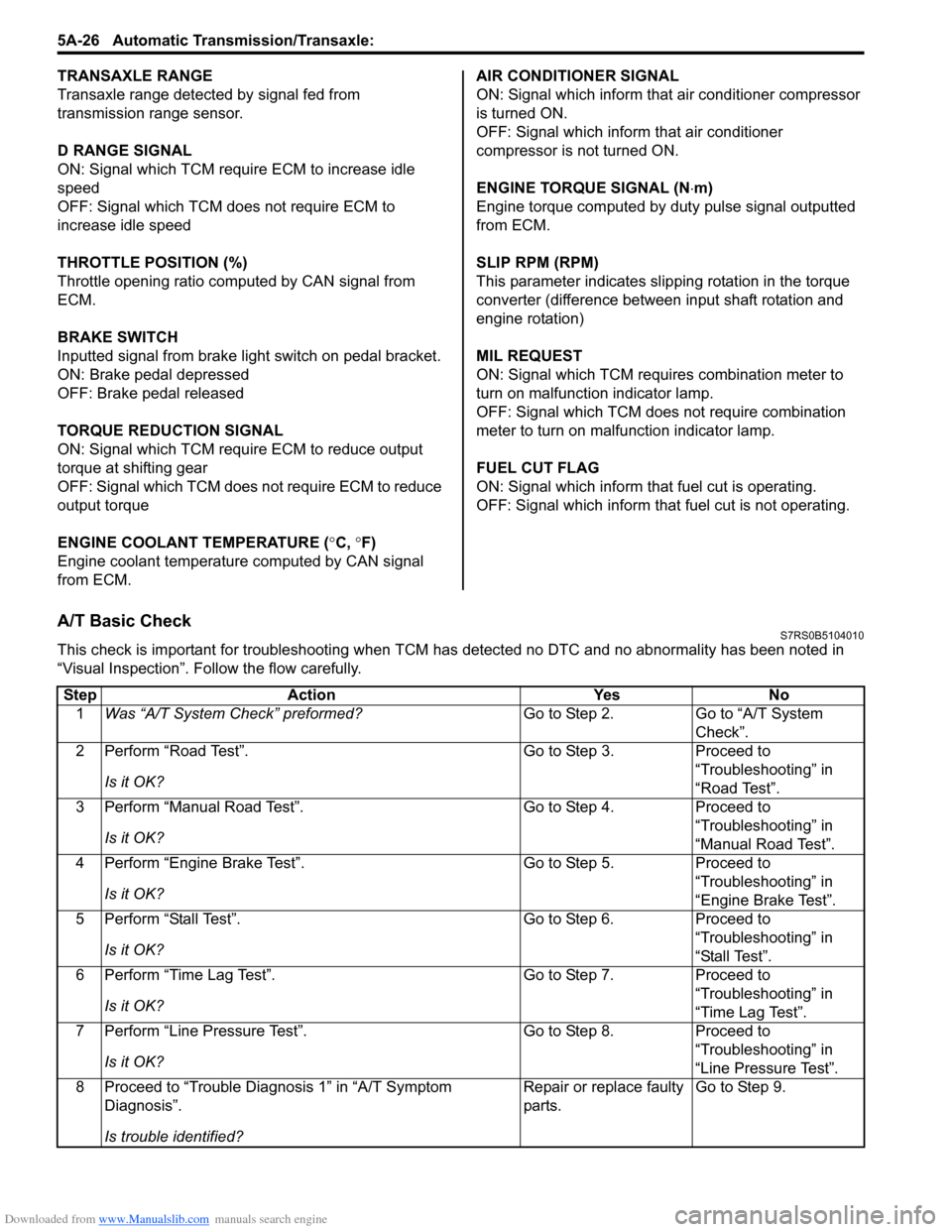
A/T Basic CheckS7RS0B5104010
This check is important for troubleshooting when TCM has detected no DTC and no abnormality has been noted in
“Visual Inspection”. Fo llow the flow carefully.
Step Action YesNo
1 Was “A/T System Check” preformed? Go to Step 2.Go to “A/T System
Check”.
2 Perform “Road Test”.
Is it OK? Go to Step 3.
Proceed to
“Troubleshooting” in
“Road Test”.
3 Perform “Manual Road Test”.
Is it OK? Go to Step 4.
Proceed to
“Troubleshooting” in
“Manual Road Test”.
4 Perform “Engine Brake Test”.
Is it OK? Go to Step 5.
Proceed to
“Troubleshooting” in
“Engine Brake Test”.
5 Perform “Stall Test”.
Is it OK? Go to Step 6.
Proceed to
“Troubleshooting” in
“Stall Test”.
6 Perform “Time Lag Test”.
Is it OK? Go to Step 7.
Proceed to
“Troubleshooting” in
“Time Lag Test”.
7 Perform “Line Pressure Test”.
Is it OK? Go to Step 8.
Proceed to
“Troubleshooting” in
“Line Pressure Test”.
8 Proceed to “Trouble Diag nosis 1” in “A/T Symptom
Diagnosis”.
Is trouble identified? Repair or replace faulty
parts.
Go to Step 9.
Page 687 of 1496
Downloaded from www.Manualslib.com manuals search engine Automatic Transmission/Transaxle: 5A-43
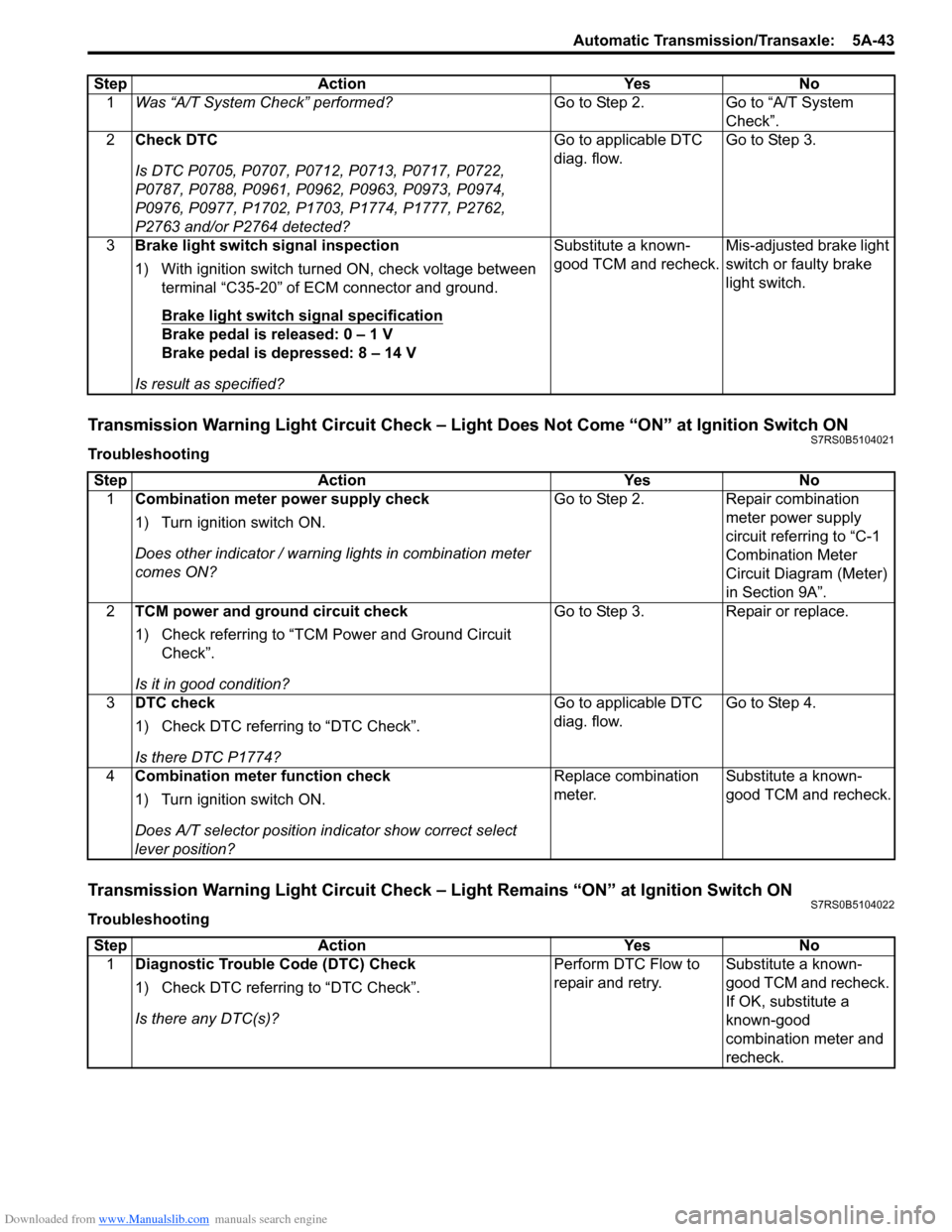
Transmission Warning Light Circuit Check – Light Does Not Come “ON” at Ignition Switch ONS7RS0B5104021
Troubleshooting
Transmission Warning Light Circuit Check – Light Remains “ON” at Ignition Switch ONS7RS0B5104022
TroubleshootingStep Action Yes No
1 Was “A/T System Check” performed? Go to Step 2. Go to “A/T System
Check”.
2 Check DTC
Is DTC P0705, P0707, P0712, P0713, P0717, P0722,
P0787, P0788, P0961, P0962, P0963, P0973, P0974,
P0976, P0977, P1702, P1703, P1774, P1777, P2762,
P2763 and/or P2764 detected? Go to applicable DTC
diag. flow.
Go to Step 3.
3 Brake light switch signal inspection
1) With ignition switch turned ON, check voltage between
terminal “C35-20” of ECM connector and ground.
Brake light switch signal specification
Brake pedal is released: 0 – 1 V
Brake pedal is depressed: 8 – 14 V
Is result as specified? Substitute a known-
good TCM and recheck.
Mis-adjusted brake light
switch or faulty brake
light switch.
Step
Action YesNo
1 Combination meter power supply check
1) Turn ignition switch ON.
Does other indicator / warnin g lights in combination meter
comes ON? Go to Step 2.
Repair combination
meter power supply
circuit referring to “C-1
Combination Meter
Circuit Diagram (Meter)
in Section 9A”.
2 TCM power and ground circuit check
1) Check referring to “TCM Power and Ground Circuit
Check”.
Is it in good condition? Go to Step 3.
Repair or replace.
3 DTC check
1) Check DTC referring to “DTC Check”.
Is there DTC P1774? Go to applicable DTC
diag. flow.
Go to Step 4.
4 Combination meter function check
1) Turn ignition switch ON.
Does A/T selector position in dicator show correct select
lever position? Replace combination
meter.
Substitute a known-
good TCM and recheck.
Step
Action YesNo
1 Diagnostic Trouble Code (DTC) Check
1) Check DTC referring to “DTC Check”.
Is there any DTC(s)? Perform DTC Flow to
repair and retry.
Substitute a known-
good TCM and recheck.
If OK, substitute a
known-good
combination meter and
recheck.
Page 888 of 1496
Downloaded from www.Manualslib.com manuals search engine 6C-6 Power Assisted Steering System:
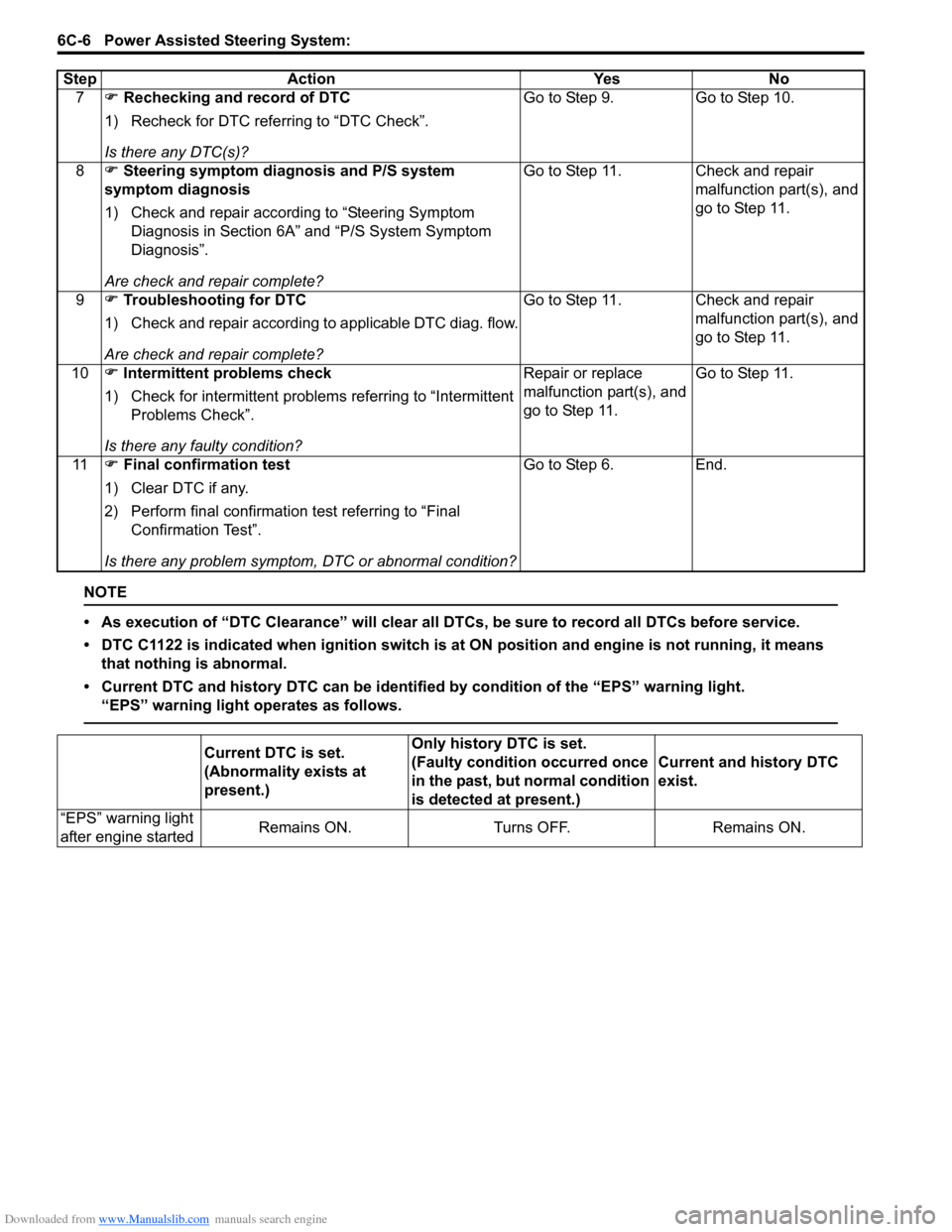
NOTE
• As execution of “DTC Clearance” will clear all DTCs, be sure to record all DTCs before service.
• DTC C1122 is indicated when ignition switch is at ON position and engine is not running, it means
that nothing is abnormal.
• Current DTC and history DTC ca n be identified by condition of the “EPS” warning light.
“EPS” warning light operates as follows.
7 �) Rechecking and record of DTC
1) Recheck for DTC referring to “DTC Check”.
Is there any DTC(s)? Go to Step 9. Go to Step 10.
8 �) Steering symptom diagnosis and P/S system
symptom diagnosis
1) Check and repair according to “Steering Symptom Diagnosis in Section 6A” and “P/S System Symptom
Diagnosis”.
Are check and repair complete? Go to Step 11. Check and repair
malfunction part(s), and
go to Step 11.
9 �) Troubleshooting for DTC
1) Check and repair according to applicable DTC diag. flow.
Are check and repair complete? Go to Step 11. Check and repair
malfunction part(s), and
go to Step 11.
10 �) Intermittent problems check
1) Check for intermittent problems referring to “Intermittent Problems Check”.
Is there any faulty condition? Repair or replace
malfunction part(s), and
go to Step 11.
Go to Step 11.
11 �) Final confirmation test
1) Clear DTC if any.
2) Perform final confirmation test referring to “Final Confirmation Test”.
Is there any problem symptom, DTC or abnormal condition? Go to Step 6. End.
Step Action Yes No
Current DTC is set.
(Abnormality exists at
present.)
Only history DTC is set.
(Faulty condition occurred once
in the past, but normal condition
is detected at present.)
Current and history DTC
exist.
“EPS” warning light
after engine started Remains ON. Turns OFF. Remains ON.
Page 890 of 1496
Downloaded from www.Manualslib.com manuals search engine 6C-8 Power Assisted Steering System:
Step 2: DTC Check, Record and Clearance
First, check DTC, referring to “DTC Check”. If DTC is
indicated, print it or write them down and then clear them
by referring to “DTC Clearance”. DTC indicates
malfunction that occurred in the system but does not
indicate whether it exists now or it occurred in the past
and the normal condition has been restored now. To
check which case applies, check the symptom in
question according to Step 5 and recheck DTC
according to Step 6 and 7.
Attempt to diagnose a trouble based on DTC in this step
only or failure to clear the DTC in this step will lead to
incorrect diagnosis, trouble diagnosis of a normal circuit
or difficulty in troubleshooting.
Step 3 and 4: Visual Inspection
As a preliminary step, be sure to perform visual check of
the items that support proper function of the P/S system
referring to “Visual Inspection”.
Step 5: Trouble Symptom Confirmation
Based on information obtained in “Step 1: Customer
Complaint Analysis: ” and “S tep 2: DTC Check, Record
and Clearance: ”, confirm trouble symptoms. Also,
reconfirm trouble symptom by performing test drive and
turning steering wheel fully to right and left at stopped
vehicle.
Step 6 and 7: Rechecking and Record of DTC
Refer to “DTC Check” for checking procedure.
Step 8: Steering Symptom Diagnosis and P/S
System Symptom Diagnosis
Perform basic steering system check according to
“Steering Symptom Diagnosis in Section 6A” first. When
the end of the flow has been reached, check the parts of
the system suspected as a possible cause referring to
“P/S System Symptom Diagnosis” and based on
symptoms appearing on the vehicle (symptoms obtained
through steps of customer complaint analysis, trouble
symptom confirmation and/or basic P/S system check)
and repair or replace faulty parts, if any.
Step 9: Troubleshooting for DTC (See each DTC
Diag. Flow)
Based on the DTC indicated in Step 6 or 7 and referring
to the applicable DTC diag. flow, locate the cause of the
trouble, namely in a sensor, switch, wire harness,
connector, actuator, P/S control module or other part and
repair or replace faulty parts.
Step 10: Intermittent Problems Check
Check parts where an intermittent trouble is easy to
occur (e.g., wire harness, connector, etc.), referring to
“Intermittent and Poor Connection Inspection in Section
00” and related circuit of DTC recorded in Step 2. Step 11: Final Confirmation Test
Confirm that the problem symptom has gone and the P/
S system is free from any abnormal conditions. If what
has been repaired is related to the DTC, clear the DTC
once, perform DTC confirmation procedure and confirm
that no DTC is indicated.
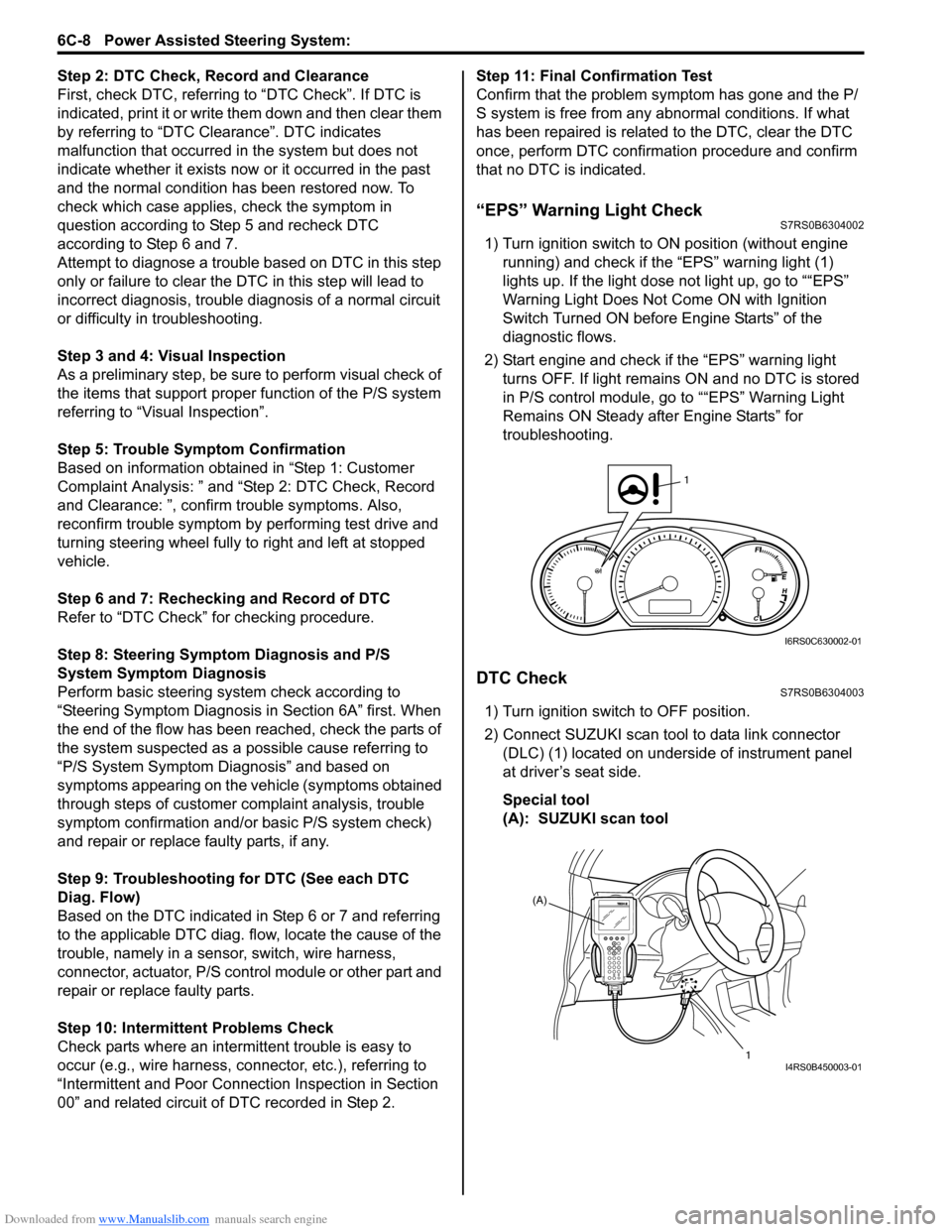
“EPS” Warning Light CheckS7RS0B6304002
1) Turn ignition switch to ON position (without engine
running) and chec k if the “EPS” warning light (1)
lights up. If the light dose not light up, go to ““EPS”
Warning Light Does Not Come ON with Ignition
Switch Turned ON before Engine Starts” of the
diagnostic flows.
2) Start engine and check if the “EPS” warning light turns OFF. If light remains ON and no DTC is stored
in P/S control module, go to ““EPS” Warning Light
Remains ON Steady after Engine Starts” for
troubleshooting.
DTC CheckS7RS0B6304003
1) Turn ignition switch to OFF position.
2) Connect SUZUKI scan tool to data link connector (DLC) (1) located on underside of instrument panel
at driver’s seat side.
Special tool
(A): SUZUKI scan tool
1
I6RS0C630002-01
(A)
1
I4RS0B450003-01
Page 898 of 1496
Downloaded from www.Manualslib.com manuals search engine 6C-16 Power Assisted Steering System:
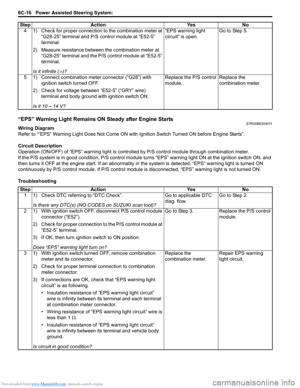
“EPS” Warning Light Remains ON Steady after Engine StartsS7RS0B6304011
Wiring Diagram
Refer to ““EPS” Warning Light Does Not Come ON with Ignition Switch Turned ON before Engine Starts”.
Circuit Description
Operation (ON/OFF) of “EPS” warning light is controlled by P/S c ontrol module through combination meter.
If the P/S system is in good condition, P/S control module tu rns “EPS” warning light ON at the ignition switch ON, and
then turns it OFF at the engine start. If an abnormality in the system is detected, “EPS” warning light is turned ON
continuously by P/S control module. If P/S control module is disconnected, “EPS” warning light is not turned ON.
Troubleshooting 4 1) Check for proper connection to the combination meter at
“G28-25” terminal and P/S control module at “E52-5”
terminal.
2) Measure resistance between the combination meter at “G28-25” terminal and the P/S control module at “E52-5”
terminal.
Is it infinite (
∞)? “EPS warning light
circuit” is open.
Go to Step 5.
5 1) Connect combination meter connector (“G28”) with ignition switch turned OFF.
2) Check for voltage between “E52-5” (“GRY” wire) terminal and body ground with ignition switch ON.
Is it 10 – 14 V? Replace the P/S control
module.
Replace the
combination meter.
Step
Action YesNo
Step Action YesNo
1 1) Check DTC referring to “DTC Check”.
Is there any DTC(s) (NO CODES on SUZUKI scan tool)? Go to applicable DTC
diag. flow.
Go to Step 2.
2 1) With ignition switch OFF, disconnect P/S control module connector (“E52”).
2) Check for proper connection to the P/S control module at “E52-5” terminal.
3) If OK, then turn ignition switch to ON position.
Does “EPS” warning light turn on? Go to Step 3.
Replace the P/S control
module.
3 1) With ignition switch turned OFF, remove combination meter and its connector.
2) Check for proper terminal connection to combination meter connector.
3) If connections are OK, ch eck that “EPS warning light
circuit” is as following.
• Insulation resistance of “EPS warning light circuit” wire is infinity between its terminal and each terminal
at combination meter connector.
• Wiring resistance of “EPS wa rning light circuit” wire is
less than 1 Ω.
• Insulation resistance of “EPS warning light circuit” wire is infinity between its terminal and vehicle body
ground.
Is circuit in good condition? Replace the
combination meter.
Repair EPS warning
light circuit.
Page 902 of 1496
Downloaded from www.Manualslib.com manuals search engine 6C-20 Power Assisted Steering System:
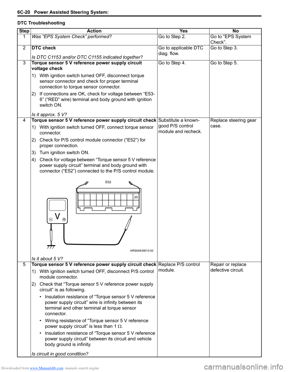
DTC TroubleshootingStep Action Yes No 1 Was “EPS System Check” performed? Go to Step 2. Go to “EPS System
Check”.
2 DTC check
Is DTC C1153 and/or DTC C1155 indicated together? Go to applicable DTC
diag. flow.
Go to Step 3.
3 Torque sensor 5 V reference power supply circuit
voltage check
1) With ignition switch turned OFF, disconnect torque
sensor connector and check for proper terminal
connection to torque sensor connector.
2) If connections are OK, check for voltage between “E53- 6” (“RED” wire) terminal and body ground with ignition
switch ON.
Is it approx. 5 V? Go to Step 4. Go to Step 5.
4 Torque sensor 5 V reference power supply circuit check
1) With ignition switch turned OFF, connect torque sensor
connector.
2) Check for P/S control module connector (“E52”) for proper connection.
3) Turn ignition switch ON.
4) Check for voltage between “Torque sensor 5 V reference power supply circuit” terminal and body ground with
connector (“E52”) connected to the P/S control module.
Is it about 5 V? Substitute a known-
good P/S control
module and recheck.
Replace steering gear
case.
5 Torque sensor 5 V reference power supply circuit check
1) With ignition switch turned OFF, disconnect P/S control
module connector.
2) Check that “Torque sensor 5 V reference power supply circuit” is as following.
• Insulation resistance of “Torque sensor 5 V reference power supply circuit” wire is infinity between its
terminal and other terminal at torque sensor
connector.
• Wiring resistance of “Torque sensor 5 V reference power supply circuit” is less than 1 Ω.
• Insulation resistance of “Torque sensor 5 V reference power supply circuit” between its circuit and vehicle
body ground is infinity.
Is circuit in good condition? Replace P/S control
module.
Repair or replace
defective circuit.
20
E52
I4RS0A630013-02
Page 904 of 1496
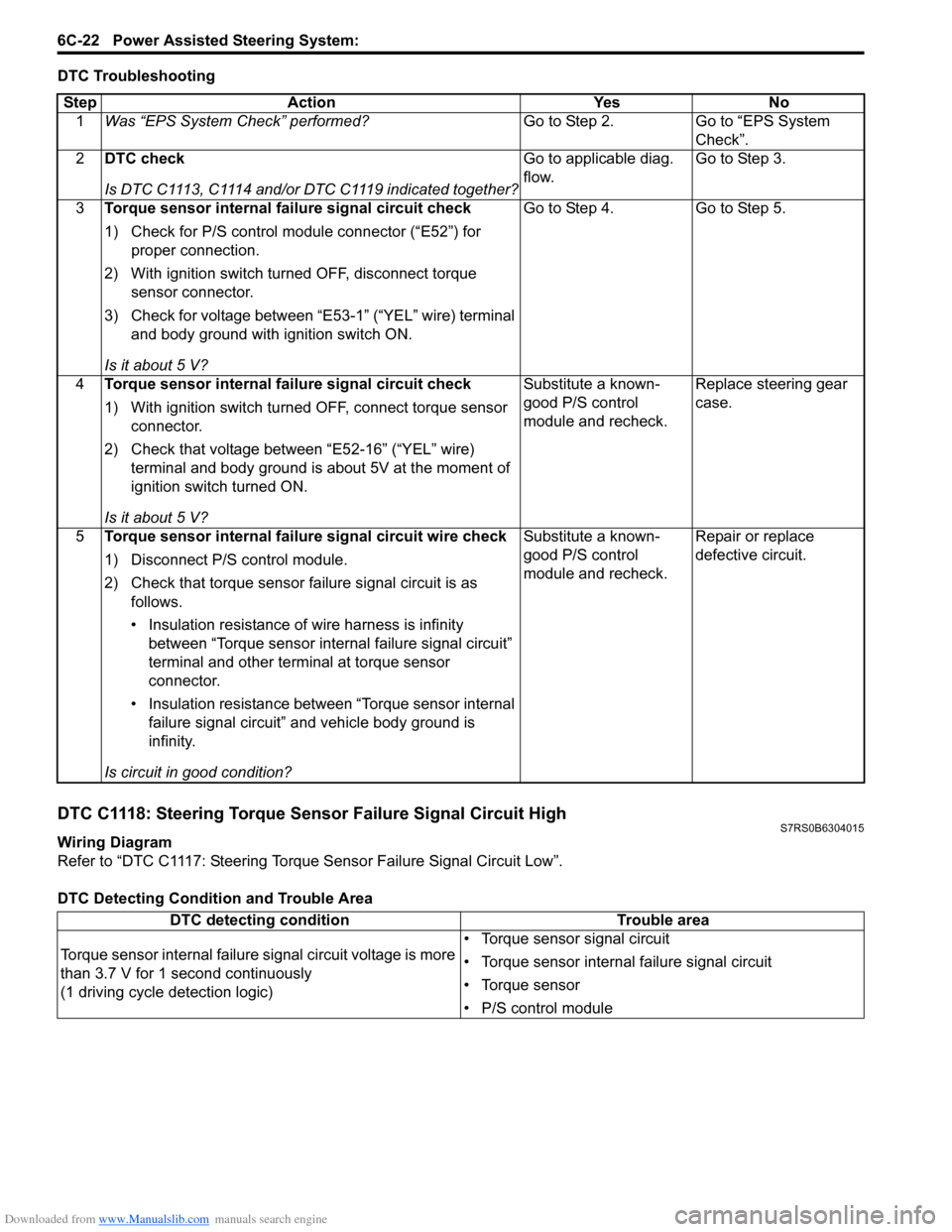
Downloaded from www.Manualslib.com manuals search engine 6C-22 Power Assisted Steering System:
DTC Troubleshooting
DTC C1118: Steering Torque Sensor Failure Signal Circuit HighS7RS0B6304015
Wiring Diagram
Refer to “DTC C1117: Steering Torque Sensor Failure Signal Circuit Low”.
DTC Detecting Condition and Trouble AreaStep Action Yes No
1 Was “EPS System Check” performed? Go to Step 2. Go to “EPS System
Check”.
2 DTC check
Is DTC C1113, C1114 and/or DTC C1119 indicated together? Go to applicable diag.
flow.
Go to Step 3.
3 Torque sensor internal failure signal circuit check
1) Check for P/S control module connector (“E52”) for
proper connection.
2) With ignition switch turned OFF, disconnect torque sensor connector.
3) Check for voltage between “E53-1” (“YEL” wire) terminal and body ground with ignition switch ON.
Is it about 5 V? Go to Step 4. Go to Step 5.
4 Torque sensor internal failure signal circuit check
1) With ignition switch turned OFF, connect torque sensor
connector.
2) Check that voltage between “E52-16” (“YEL” wire) terminal and body ground is about 5V at the moment of
ignition switch turned ON.
Is it about 5 V? Substitute a known-
good P/S control
module and recheck.
Replace steering gear
case.
5 Torque sensor internal failure signal circuit wire check
1) Disconnect P/S control module.
2) Check that torque sensor failure signal circuit is as
follows.
• Insulation resistance of wire harness is infinity between “Torque sensor internal failure signal circuit”
terminal and other terminal at torque sensor
connector.
• Insulation resistance between “Torque sensor internal failure signal circuit” and vehicle body ground is
infinity.
Is circuit in good condition? Substitute a known-
good P/S control
module and recheck.
Repair or replace
defective circuit.
DTC detecting condition
Trouble area
Torque sensor internal failure signal circuit voltage is more
than 3.7 V for 1 second continuously
(1 driving cycle detection logic) • Torque sensor signal circuit
• Torque sensor internal failure signal circuit
• Torque sensor
• P/S control module
Page 905 of 1496
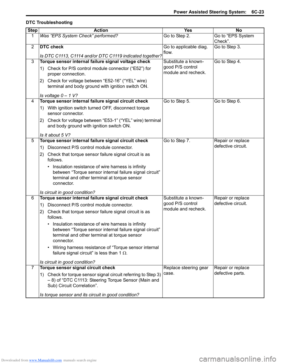
Downloaded from www.Manualslib.com manuals search engine Power Assisted Steering System: 6C-23
DTC TroubleshootingStep Action Yes No 1 Was “EPS System Check” performed? Go to Step 2. Go to “EPS System
Check”.
2 DTC check
Is DTC C1113, C1114 and/or DTC C1119 indicated together? Go to applicable diag.
flow.
Go to Step 3.
3 Torque sensor internal failure signal voltage check
1) Check for P/S control module connector (“E52”) for
proper connection.
2) Check for voltage between “E52-16” (“YEL” wire) terminal and body ground with ignition switch ON.
Is voltage 0 – 1 V? Substitute a known-
good P/S control
module and recheck.
Go to Step 4.
4 Torque sensor internal failure signal circuit check
1) With ignition switch turned OFF, disconnect torque
sensor connector.
2) Check for voltage between “E53-1” (“YEL” wire) terminal and body ground with ignition switch ON.
Is it about 5 V? Go to Step 5. Go to Step 6.
5 Torque sensor internal failure signal circuit check
1) Disconnect P/S control module connector.
2) Check that torque sensor failure signal circuit is as
follows.
• Insulation resistance of wire harness is infinity between “Torque sensor internal failure signal circuit”
terminal and other terminal at torque sensor
connector.
Is circuit in good condition? Go to Step 7. Repair or replace
defective circuit.
6 Torque sensor internal failure signal circuit check
1) Disconnect P/S control module connector.
2) Check that torque sensor failure signal circuit is as
follows.
• Insulation resistance of wire harness is infinity between “Torque sensor internal failure signal circuit”
terminal and other terminal at torque sensor
connector.
• Wiring harness resistance of “Torque sensor internal failure signal circuit” is less than 1 Ω.
Is circuit in good condition? Substitute a known-
good P/S control
module and recheck.
Repair or replace
defective circuit.
7 Torque sensor signal circuit check
1) Check for torque sensor signal circuit referring to Step 3)
– 8) of “DTC C1113: Steering Torque Sensor (Main and
Sub) Circuit Correlation”.
Is torque sensor and its circuit in good condition? Replace steering gear
case.
Repair or replace
defective parts.