Torque specifications SUZUKI SWIFT 2006 2.G Service Service Manual
[x] Cancel search | Manufacturer: SUZUKI, Model Year: 2006, Model line: SWIFT, Model: SUZUKI SWIFT 2006 2.GPages: 1496, PDF Size: 34.44 MB
Page 865 of 1496
Downloaded from www.Manualslib.com manuals search engine Clutch: 5C-13
Clutch Release System InspectionS7RS0B5306017
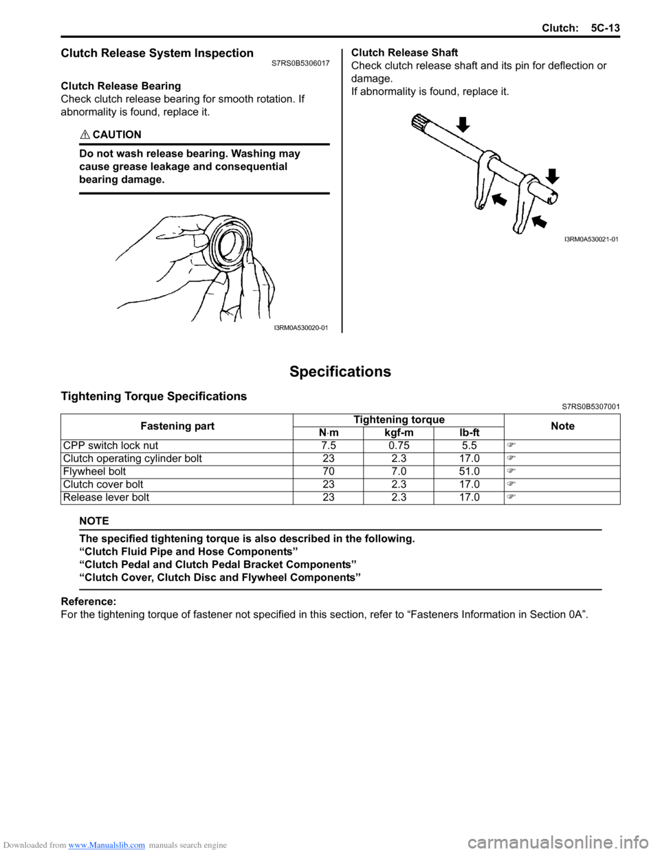
Clutch Release Bearing
Check clutch release bearing for smooth rotation. If
abnormality is found, replace it.
CAUTION!
Do not wash release bearing. Washing may
cause grease leakage and consequential
bearing damage.
Clutch Release Shaft
Check clutch release shaft and its pin for deflection or
damage.
If abnormality is found, replace it.
Specifications
Tightening Torque SpecificationsS7RS0B5307001
NOTE
The specified tightening torque is also described in the following.
“Clutch Fluid Pipe and Hose Components”
“Clutch Pedal and Clutch Pedal Bracket Components”
“Clutch Cover, Clutch Disc and Flywheel Components”
Reference:
For the tightening torque of fastener not specified in this section, refer to “Fasteners Information in Section 0A”.
I3RM0A530020-01
I3RM0A530021-01
Fastening part Tightening torque
Note
N ⋅mkgf-mlb-ft
CPP switch lock nut 7.5 0.75 5.5 �)
Clutch operating cylinder bolt 23 2.3 17.0 �)
Flywheel bolt 70 7.0 51.0 �)
Clutch cover bolt 23 2.3 17.0 �)
Release lever bolt 23 2.3 17.0 �)
Page 867 of 1496

Downloaded from www.Manualslib.com manuals search engine Table of Contents 6- i
6
Section 6
CONTENTS
Steering
Precautions ................................................. 6-1
Precautions............................................................. 6-1
Precautions on Steering........................................ 6-1
Steering General Diagnosi s.................... 6A-1
Precautions........................................................... 6A-1
Precautions for Steering Diagnosis ..................... 6A-1
Diagnostic Information and Procedures ............ 6A-2 Steering Symptom Diagnosis .............................. 6A-2
Steering Wheel and Column ................... 6B-1
Precautions........................................................... 6B-1
Service Precautions of Steering Wheel and Column.............................................................. 6B-1
General Description ............................................. 6B-1 Steering Wheel and Column Construction .......... 6B-1
Diagnostic Information and Procedures ............ 6B-2 Checking Steering Column for Accident Damage ............................................................ 6B-2
Repair Instructions .............................................. 6B-3 Steering Wheel and Column Construction .......... 6B-3
Steering Wheel Removal and Installation ........... 6B-4
Contact Coil Cable Assembly Removal and Installation ......................................................... 6B-5
Centering Contact Coil Cable Assembly ............. 6B-6
Contact Coil Cable Assembly Inspection ............ 6B-6
Steering Angle Sensor Removal and Installation ......................................................... 6B-6
Steering Angle Sensor Inspection ....................... 6B-6
Steering Column Removal and Installation ......... 6B-7
Steering Column Inspecti on ................................ 6B-8
Ignition Switch Cylinder Assembly Removal and Installation (Non- Keyless Start Model)...... 6B-9
Steering Lock Assembly (Ignition Switch) Removal and Installation................................... 6B-9
Steering Lower Shaft Removal and Installation ....................................................... 6B-10
Specifications ..................................................... 6B-11
Tightening Torque Specifications ...................... 6B-11
Special Tools and Equipmen t ........................... 6B-11
Special Tool ...................................................... 6B-11
Power Assisted Steering System........... 6C-1
Precautions........................................................... 6C-1 Steering System Note .........................................6C-1
Precautions in Diagnosing Troubles ...................6C-1
General Description .............................................6C-2 P/S System Description ......................................6C-2
EPS Diagnosis General Descr iption ...................6C-3
On-Board Diagnostic System Description ...........6C-3
Schematic and Routing Diagram ........................6C-4 EPS System Wiring Circuit Diagram ...................6C-4
Diagnostic Information and Procedures ............6C-5 EPS System Check .............. ...............................6C-5
“EPS” Warning Light Check . ...............................6C-8
DTC Check..........................................................6C-8
DTC Clearance ...................................................6C-9
DTC Table ...........................................................6C-9
Scan Tool Data .................................................6C-11
Visual Inspection ...............................................6C-12
P/S System Symptom Diagnosis ......................6C-12
Serial Data Link Circuit Check ..........................6C-13
“EPS” Warning Light Do es Not Come ON with
Ignition Switch Turn ed ON before Engine
Starts ...............................................................6C-15
“EPS” Warning Light Remains ON Steady after Engine Starts ..........................................6C-16
DTC C1113: Steering Torque Sensor (Main and Sub) Circuit Correlation ............................6C-17
DTC C1114: Steering Torque Sensor Reference Power Supply Circuit .....................6C-19
DTC C1117: Steering Torque Sensor Failure Signal Circuit Low ...........................................6C-21
DTC C1118: Steering Torque Sensor Failure Signal Circuit High...........................................6C-22
DTC C1119: Steering Torque Sensor Power Supply Circuit ..................................................6C-24
DTC C1121 / C1123 / C1124: VSS Circuit
Failure .............................................................6C-26
DTC C1122: Engine Speed Signal....................6C-28
DTC C1141 / C1142 / C1143 / C1145: P/S Motor Circuit Failure ........................................6C-30
DTC C1153: P/S Control Module Power Supply Circuit Voltage Low .............................6C-32
DTC C1155: P/S Control Module Failure ..........6C-33
P/S Control Module Power Supply and Ground Circuit Check ......................................6C-34
Inspection of P/S Control Module and Its Circuits ............................................................6C-35
Page 868 of 1496
Downloaded from www.Manualslib.com manuals search engine 6-ii Table of Contents
Steering Wheel Play Check ..............................6C-39
Steering Force Check .......................................6C-39
Repair Instructions ........... .................................6C-40
Steering Gear Case Assembly Components ....6C-40
Tie-Rod End Boot On-Vehic le Inspection .........6C-41
Tie-Rod End Removal and Installation..............6C-41
Tie-Rod End Inspection.....................................6C-42
Steering Shaft Joint On-Vehicle Inspection.......6C-42
Steering Gear Case Assembly Removal and Installation .......................................................6C-42
Steering Rack Boot Inspec tion ..........................6C-43
Tie-Rod / Rack Boot Removal and Installation ..6C-43 Steering Rack Plunger Removal and
Installation .......................................................6C-45
Steering Rack Plunger Inspection .....................6C-45
P/S Control Module Removal and Installation...6C-46
Torque Sensor and Its Circuit Inspection ..........6C-46
P/S Motor and Its Circuit Inspection ..................6C-47
Specifications ..................... ................................6C-48
Tightening Torque Specifications ......................6C-48
Special Tools and Equipmen t ...........................6C-49
Recommended Service Material .......................6C-49
Special Tool ......................................................6C-49
Page 879 of 1496
Downloaded from www.Manualslib.com manuals search engine Steering Wheel and Column: 6B-8
Installation
CAUTION!
After tightening steering column mounting
nuts, shaft joint bolts should be tightened.
Wrong tightening order could cause a
damage to shaft joint.
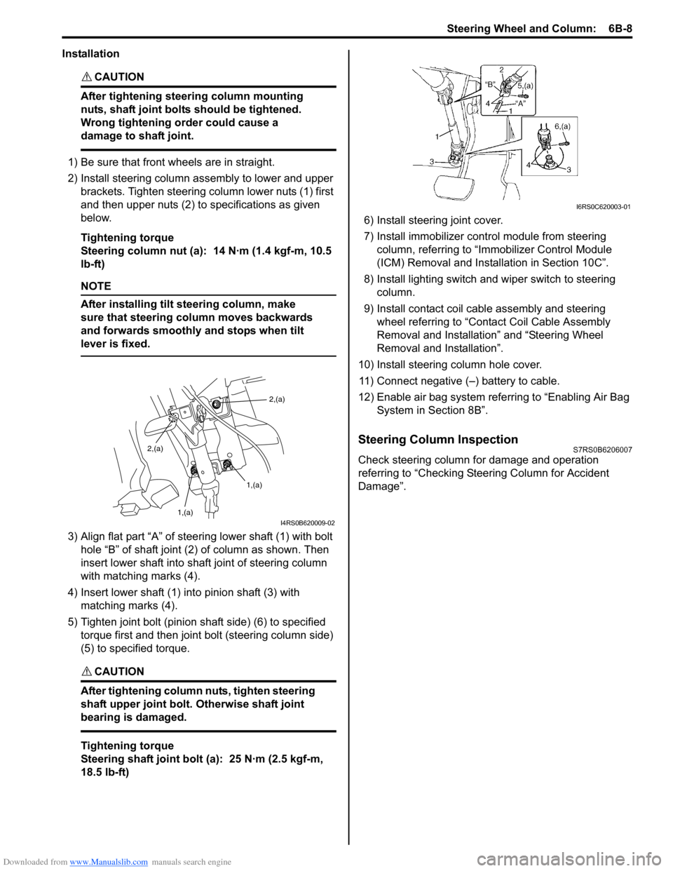
1) Be sure that front wheels are in straight.
2) Install steering column assembly to lower and upper brackets. Tighten steering column lower nuts (1) first
and then upper nuts (2) to specifications as given
below.
Tightening torque
Steering column nut (a): 14 N·m (1.4 kgf-m, 10.5
lb-ft)
NOTE
After installing tilt steering column, make
sure that steering column moves backwards
and forwards smoothly and stops when tilt
lever is fixed.
3) Align flat part “A” of stee ring lower shaft (1) with bolt
hole “B” of shaft joint (2) of column as shown. Then
insert lower shaft into shaf t joint of steering column
with matching marks (4).
4) Insert lower shaft (1) into pinion shaft (3) with matching marks (4).
5) Tighten joint bolt (pinion shaft side) (6) to specified torque first and then joint bolt (steering column side)
(5) to specified torque.
CAUTION!
After tightening column nuts, tighten steering
shaft upper joint bolt. Otherwise shaft joint
bearing is damaged.
Tightening torque
Steering shaft joint bolt (a): 25 N·m (2.5 kgf-m,
18.5 lb-ft) 6) Install steering joint cover.
7) Install immobilizer cont
rol module from steering
column, referring to “Immo bilizer Control Module
(ICM) Removal and Installation in Section 10C”.
8) Install lighting switch and wiper switch to steering column.
9) Install contact coil cable assembly and steering wheel referring to “Conta ct Coil Cable Assembly
Removal and Installation” and “Steering Wheel
Removal and Installation”.
10) Install steering column hole cover. 11) Connect negative (–) battery to cable.
12) Enable air bag system refe rring to “Enabling Air Bag
System in Section 8B”.
Steering Column InspectionS7RS0B6206007
Check steering column for damage and operation
referring to “Checking Steering Column for Accident
Damage”.
2,(a)
1,(a)
1,(a)
2,(a)
I4RS0B620009-02
I6RS0C620003-01
Page 882 of 1496
Downloaded from www.Manualslib.com manuals search engine 6B-11 Steering Wheel and Column:
Specifications
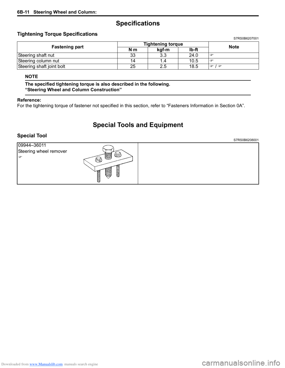
Tightening Torque SpecificationsS7RS0B6207001
NOTE
The specified tightening torque is also described in the following.
“Steering Wheel and Column Construction”
Reference:
For the tightening torque of fastener not specified in this section, refer to “Fasteners Information in Section 0A”.
Special Tools and Equipment
Special ToolS7RS0B6208001
Fastening part Tightening torque
Note
N ⋅mkgf-mlb-ft
Steering shaft nut 33 3.3 24.0 �)
Steering column nut 14 1.4 10.5 �)
Steering shaft joint bolt 25 2.5 18.5 �) / �)
09944–36011
Steering wheel remover
�)
Page 930 of 1496
Downloaded from www.Manualslib.com manuals search engine 6C-48 Power Assisted Steering System:
Specifications
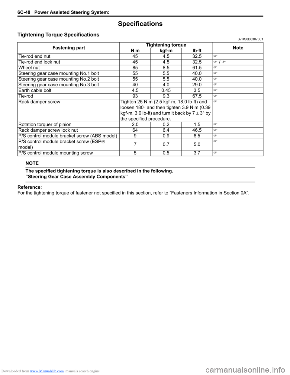
Tightening Torque SpecificationsS7RS0B6307001
NOTE
The specified tightening torque is also described in the following.
“Steering Gear Case Assembly Components”
Reference:
For the tightening torque of fastener not specified in this section, refer to “Fasteners Information in Section 0A”.
Fastening part
Tightening torque
Note
N ⋅mkgf-mlb-ft
Tie-rod end nut 454.5 32.5 �)
Tie-rod end lock nut 454.5 32.5 �) / �)
Wheel nut 858.5 61.5 �)
Steering gear case mounting No.1 bolt 555.5 40.0 �)
Steering gear case mounting No.2 bolt 555.5 40.0 �)
Steering gear case mounting No.3 bolt 404.0 29.0 �)
Earth cable bolt 4.5 0.45 3.5�)
Tie-rod 939.3 67.5 �)
Rack damper screw Tighten 25 N⋅m (2.5 kgf-m, 18.0 lb-ft) and
loosen 180 ° and then tighten 3.9 N ⋅m (0.39
kgf-m, 3.0 lb-ft) and turn it back by 7 ± 3° by
the specified procedure. �)
Rotation torquer of pinion 2.00.2 1.5 �)
Rack damper screw lock nut 646.4 46.5 �)
P/S control module bracket screw (ABS model) 9 0.9 6.5�)
P/S control module bracket screw (ESP ®
model) 70
.7 5 .0 �)
P/S control module mounting screw 50.5 3.7 �)
Page 933 of 1496

Downloaded from www.Manualslib.com manuals search engine Table of Contents 7- i
7
Section 7
CONTENTS
HVAC
Precautions ................................................. 7-1
Precautions............................................................. 7-1
Precautions on HVAC ........................................... 7-1
Heater and Ventilation.... ......................... 7A-1
General Description ............................................. 7A-1
Heater and Ventilation Construction ................... 7A-1
Schematic and Routing Diagram ........................ 7A-2 Heater and Ventilation Wiring Circuit Diagram .... 7A-2
Diagnostic Information and Procedures ............ 7A-3 Heater and Ventilation Symptom Diagnosis........ 7A-3
Repair Instructions .............................................. 7A-4 HVAC Unit Components ..................................... 7A-4
HVAC Unit Removal and Installation .................. 7A-4
Blower Motor Removal and Installation............... 7A-4
Blower Motor Inspection ..................................... 7A-4
Blower Motor Resistor Removal and Installation ......................................................... 7A-5
Blower Motor Resistor Inspection ....................... 7A-5
Blower Motor Relay Inspection ........................... 7A-6
HVAC Control Unit Components ......................... 7A-6
HVAC Control Unit Remova l and Installation ...... 7A-7
Blower Speed Selector In spection ...................... 7A-9
Air Intake Selector Inspec tion ............................. 7A-9
Air Intake Control Actuator Removal and Installation ......................................................... 7A-9
Air Intake Control Actuator Inspection .............. 7A-10
Center Ventilation Louver Removal and Installation ....................................................... 7A-10
Side Ventilation Louver Removal and Installation ....................................................... 7A-11
HVAC Air Filter Removal and Installation (If Equipped)........................................................ 7A-12
HVAC Air Filter Inspection (If Equipped) ........... 7A-12
Air Conditioning System... ...................... 7B-1
Manual Type ............................................................ 7B-1
Precautions........................................................... 7B-1A/C System Caution ............................................ 7B-1
Precautions on Servicing A/C System ................ 7B-1
General Description ............................................. 7B-3 Refrigerant Type Identifica tion ............................ 7B-3
Sub-Cool A/C System Description ...................... 7B-4
A/C Operation Description .................................. 7B-4 Schematic and Routing Diagram ........................7B-5
Major Components of A/C System ...................... 7B-5
A/C System Wiring Diagram ............................... 7B-6
Diagnostic Information and Procedures ............7B-7 A/C System Symptom Diagnosis ........................ 7B-7
Abnormal Noise Sympto m Diagnosis of A/C
System .............................................................. 7B-9
A/C System Performance Inspection ................ 7B-10
A/C System Inspection at ECM ......................... 7B-15
Repair Instructions ........... .................................7B-16
Operation Procedure for Re frigerant Charge .... 7B-16
Condenser Assembly On-Vehicle Inspection .... 7B-21
Condenser Assembly Removal and Installation ....................................................... 7B-21
Receiver/Dryer Removal and Installation .......... 7B-22
HVAC Unit Components ................................... 7B-23
HVAC Unit Removal and In stallation ................ 7B-24
Evaporator Inspection ....................................... 7B-24
Evaporator Thermistor (Evaporator Temperature Sensor) Removal and
Installation ....................................................... 7B-25
Evaporator Thermistor (Evaporator Temperature Sensor) Inspec tion..................... 7B-25
Expansion Valve Removal and Installation ....... 7B-26
Expansion Valve Inspection .............................. 7B-26
A/C Refrigerant Pressure Sensor and Its Circuit Inspection............................................. 7B-26
A/C Refrigerant Pressu re Sensor Removal
and Installation ................................................ 7B-26
A/C Switch Inspection ....................................... 7B-27
Compressor Relay Inspection ........................... 7B-27
Compressor Drive Belt Inspection and Adjustment ...................................................... 7B-27
Compressor Drive Belt Removal and Installation ....................................................... 7B-28
Compressor Assembly Removal and Installation ....................................................... 7B-28
Compressor Assembly Components................. 7B-29
Magnet Clutch Inspection.................................. 7B-29
Magnet Clutch Removal and Installation........... 7B-29
Relief Valve Inspection...................................... 7B-31
Relief Valve Removal and Installation............... 7B-32
Specifications .................... .................................7B-32
Tightening Torque Specifications ...................... 7B-32
Special Tools and Equipmen t ...........................7B-33
Page 974 of 1496
Downloaded from www.Manualslib.com manuals search engine 7B-26 Air Conditioning System: Manual Type
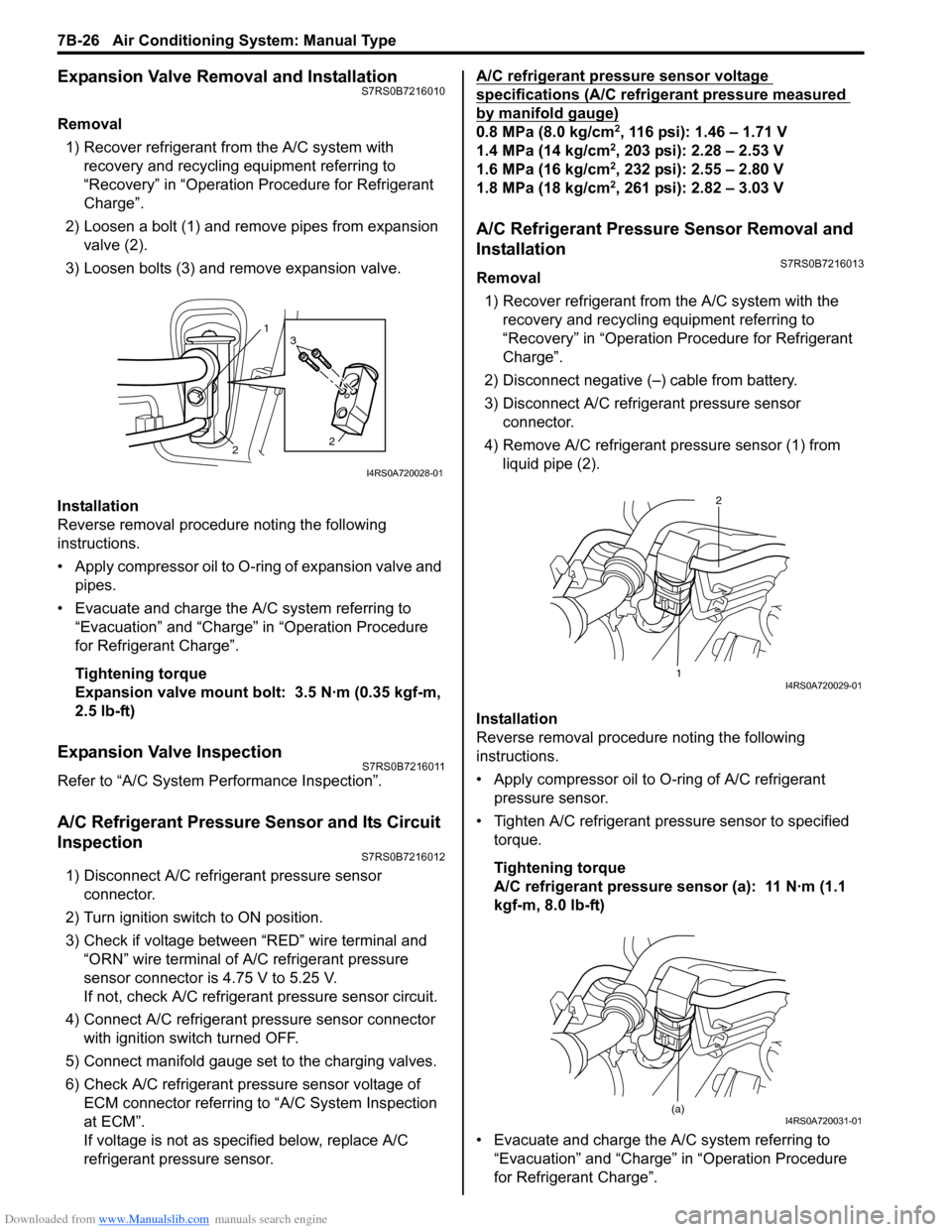
Expansion Valve Removal and InstallationS7RS0B7216010
Removal1) Recover refrigerant fr om the A/C system with
recovery and recycling equipment referring to
“Recovery” in “Operation Procedure for Refrigerant
Charge”.
2) Loosen a bolt (1) and remove pipes from expansion valve (2).
3) Loosen bolts (3) and remove expansion valve.
Installation
Reverse removal procedure noting the following
instructions.
• Apply compressor oil to O-ring of expansion valve and pipes.
• Evacuate and charge the A/C system referring to “Evacuation” and “Charge” in “Operation Procedure
for Refrigerant Charge”.
Tightening torque
Expansion valve mount bolt: 3.5 N·m (0.35 kgf-m,
2.5 lb-ft)
Expansion Valve InspectionS7RS0B7216011
Refer to “A/C System Performance Inspection”.
A/C Refrigerant Pressure Sensor and Its Circuit
Inspection
S7RS0B7216012
1) Disconnect A/C refrigerant pressure sensor connector.
2) Turn ignition switch to ON position.
3) Check if voltage between “RED” wire terminal and “ORN” wire terminal of A/C refrigerant pressure
sensor connector is 4.75 V to 5.25 V.
If not, check A/C refrigerant pressure sensor circuit.
4) Connect A/C refrigerant pressure sensor connector with ignition switch turned OFF.
5) Connect manifold gauge set to the charging valves.
6) Check A/C refrigerant pressure sensor voltage of ECM connector referring to “A/C System Inspection
at ECM”.
If voltage is not as specified below, replace A/C
refrigerant pressure sensor. A/C refrigerant pressure sensor voltage
specifications (A/C refrigerant pressure measured
by manifold gauge)
0.8 MPa (8.0 kg/cm2, 116 psi): 1.46 – 1.71 V
1.4 MPa (14 kg/cm2, 203 psi): 2.28 – 2.53 V
1.6 MPa (16 kg/cm2, 232 psi): 2.55 – 2.80 V
1.8 MPa (18 kg/cm2, 261 psi): 2.82 – 3.03 V
A/C Refrigerant Pressure Sensor Removal and
Installation
S7RS0B7216013
Removal
1) Recover refrigerant from the A/C system with the recovery and recycling equipment referring to
“Recovery” in “Operation Procedure for Refrigerant
Charge”.
2) Disconnect negative (–) cable from battery.
3) Disconnect A/C refrigerant pressure sensor connector.
4) Remove A/C refrigerant pressure sensor (1) from liquid pipe (2).
Installation
Reverse removal procedure noting the following
instructions.
• Apply compressor oil to O-ring of A/C refrigerant
pressure sensor.
• Tighten A/C refrigerant pressure sensor to specified torque.
Tightening torque
A/C refrigerant pressure sensor (a): 11 N·m (1.1
kgf-m, 8.0 lb-ft)
• Evacuate and charge the A/C system referring to “Evacuation” and “Charge” in “Operation Procedure
for Refrigerant Charge”.
1
2 2
3
I4RS0A720028-01
1 2I4RS0A720029-01
(a)I4RS0A720031-01
Page 980 of 1496
Downloaded from www.Manualslib.com manuals search engine 7B-32 Air Conditioning System: Manual Type
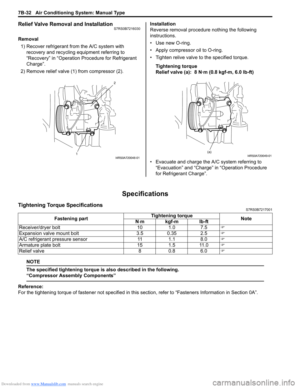
Relief Valve Removal and InstallationS7RS0B7216030
Removal1) Recover refrigerant fr om the A/C system with
recovery and recycling equipment referring to
“Recovery” in “Operation Procedure for Refrigerant
Charge”.
2) Remove relief valve (1) from compressor (2). Installation
Reverse removal procedure nothing the following
instructions.
• Use new O-ring.
• Apply compressor oil to O-ring.
• Tighten relive valve to the specified torque.
Tightening torque
Relief valve (a): 8 N·m (0.8 kgf-m, 6.0 lb-ft)
• Evacuate and charge the A/C system referring to “Evacuation” and “Charge” in “Operation Procedure
for Refrigerant Charge”.
Specifications
Tightening Torque SpecificationsS7RS0B7217001
NOTE
The specified tightening torque is also described in the following.
“Compressor Assembly Components”
Reference:
For the tightening torque of fastener not specified in this section, refer to “Fasteners Information in Section 0A”.
12I4RS0A720048-01
(a)I4RS0A720049-01
Fastening part
Tightening torque
Note
N ⋅mkgf-mlb-ft
Receiver/dryer bolt 10 1.0 7.5 �)
Expansion valve mount bolt 3.5 0.35 2.5 �)
A/C refrigerant pressure sensor 11 1.1 8.0 �)
Armature plate bolt 15 1.5 11.0 �)
Relief valve 8 0.8 6.0 �)
Page 1029 of 1496
Downloaded from www.Manualslib.com manuals search engine Table of Contents 8- i
8
Section 8
CONTENTS
Restraint
Precautions ................................................. 8-1
Precautions............................................................. 8-1
Precautions on Restraint ....................................... 8-1
Seat Belts .......... ............................... ........ 8A-1
Precautions........................................................... 8A-1
Precautions on Service a nd Diagnosis of Seat
Belt .................................................................... 8A-1
General Description ............................................. 8A-1 Seat Belt Construction ........................................ 8A-1
Diagnostic Information and Procedures ............ 8A-2 Repair and Inspection Required after Accident ............................................................ 8A-2
Repair Instructions .............................................. 8A-3 Front Seat Belt Components ............................... 8A-3
Front Seat Belt Removal and Installation ............ 8A-4
Front Seat Belt Inspection ................................... 8A-4
Rear Seat Belt Components ............................... 8A-6
Rear Seat Belt Removal and Installation ............ 8A-7
Rear Seat Belt Inspection ................................... 8A-7
Specifications ....................................................... 8A-7
Tightening Torque Specifications ........................ 8A-7
Air Bag System ............... ......................... 8B-1
Precautions........................................................... 8B-1
Precautions on Service and Diagnosis of Air Bag System....................................................... 8B-1
Precautions on Handling and Storage of Air Bag System Components . ................................ 8B-2
Precautions on Disposal of Air Bag and Seat
Belt Pretensioner .............................................. 8B-5
General Description ............................................. 8B-5 Air Bag System Construction .............................. 8B-5
Air Bag System Input / Output Table .................. 8B-6
Schematic and Routing Diagram ........................ 8B-7 Air Bag System Wiring Circuit Diagram .............. 8B-7
Component Locatio n ........................................... 8B-9
Air Bag System Components, Wiring and Connectors Location ......................................... 8B-9
Diagnostic Information and Procedures .......... 8B-10 Air Bag Diagnostic System Check .................... 8B-10
Air Bag Diagnostic System Check Flow ............ 8B-10
DTC Table ......................................................... 8B-11
DTC Check ....................................................... 8B-12 DTC Clearance ................................................. 8B-12
Scan Tool Data ................................................. 8B-13
“AIR BAG” Warning Right Comes ON Steady .. 8B-13
“AIR BAG” Warning Right Does Not Come
ON ................................................................... 8B-15
“AIR BAG” Warning Right Flashes .................... 8B-16
DTC B1013: SDM fault...................................... 8B-17
DTC B1014: “AIR BAG” Warning Right Circuit Failure ............................................................. 8B-17
DTC B1016: Power Source Voltage High ......... 8B-18
DTC B1017: Power Source Voltage Low .......... 8B-20
DTC B1021: Front Air Bag Module Deployed ... 8B-22
DTC B1024 / B1025: Side-Air Bag (Driver / Passenger) Deployed...................................... 8B-22
DTC B1026: Pretensioner Activated ................. 8B-23
DTC B1027: Reusable Number Exceeded ....... 8B-24
DTC B1031: Driver Air Bag Initiator Circuit
Resistance High .............................................. 8B-24
DTC B1032: Driver Air Bag Initiator Circuit
Resistance Low ............................................... 8B-29
DTC B1033: Driver Air Bag Initiator Circuit
Short to Ground............................................... 8B-34
DTC B1034: Driver Air Bag Initiator Circuit
Short to Power Circuit .... ................................. 8B-39
DTC B1041: Passenger Air Bag Initiator Circuit Resistance High ................................... 8B-44
DTC B1042: Passenger Air Bag Initiator Circuit Resistance Low.................................... 8B-47
DTC B1043: Passenger Air Bag Initiator Circuit Short to Ground ................................... 8B-50
DTC B1044: Passenger Air Bag Initiator Circuit Short to Power Circ uit .......................... 8B-53
DTC B1051 / B1055: Driver / Passenger Pretensioner Initiator Circuit Resistance
High ................................................................. 8B-56
DTC B1052 / B1056: Driver / Passenger Pretensioner Initiator Circu it Resistance Low .. 8B-58
DTC B1053 / B1057: Driver / Passenger Pretensioner Initiator Circuit Short to Ground .. 8B-60
DTC B1054 / B1058: Driver / Passenger Pretensioner Initiator Circuit Short to Power
Circuit .............................................................. 8B-62
DTC B1061 / B1065: Driver / Passenger Side- Air Bag Initiator Circuit Resistance High ......... 8B-64