air line SUZUKI SWIFT 2006 2.G Service Service Manual
[x] Cancel search | Manufacturer: SUZUKI, Model Year: 2006, Model line: SWIFT, Model: SUZUKI SWIFT 2006 2.GPages: 1496, PDF Size: 34.44 MB
Page 529 of 1496
Downloaded from www.Manualslib.com manuals search engine Rear Brakes: 4C-5
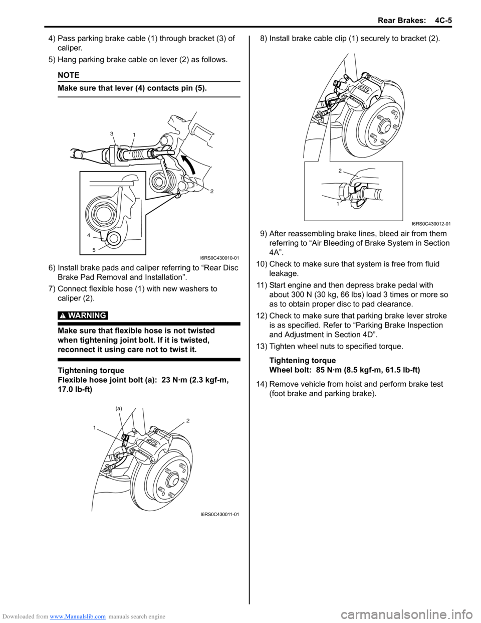
4) Pass parking brake cable (1) through bracket (3) of caliper.
5) Hang parking brake cable on lever (2) as follows.
NOTE
Make sure that lever (4) contacts pin (5).
6) Install brake pads and caliper referring to “Rear Disc Brake Pad Removal and Installation”.
7) Connect flexible hose (1) with new washers to caliper (2).
WARNING!
Make sure that flexible hose is not twisted
when tightening joint bolt. If it is twisted,
reconnect it using care not to twist it.
Tightening torque
Flexible hose joint bolt (a): 23 N·m (2.3 kgf-m,
17.0 lb-ft) 8) Install brake cable clip (1) securely to bracket (2).
9) After reassembling brake lines, bleed air from them
referring to “Air Bleeding of Brake System in Section
4A”.
10) Check to make sure that system is free from fluid
leakage.
11) Start engine and then depress brake pedal with about 300 N (30 kg, 66 lbs) load 3 times or more so
as to obtain proper disc to pad clearance.
12) Check to make sure that parking brake lever stroke is as specified. Refer to “Parking Brake Inspection
and Adjustment in Section 4D”.
13) Tighten wheel nuts to specified torque.
Tightening torque
Wheel bolt: 85 N·m (8.5 kgf-m, 61.5 lb-ft)
14) Remove vehicle from hoist and perform brake test (foot brake and parking brake).
1
23
45
I6RS0C430010-01
1 (a)2
I6RS0C430011-01
1
2
I6RS0C430012-01
Page 554 of 1496
Downloaded from www.Manualslib.com manuals search engine 4E-15 ABS:
EBD Warning Light (Brake Warning Light) Comes ON SteadyS7RS0B4504010
Wiring Diagram
Refer to “ABS Warning Light Does Not Come ON at Ignition Switch ON”.
Circuit Description
EBD warning light (brake warn ing light) is controlled by parking brake switch, brake fluid level switch and ABS
hydraulic unit / control module assembly throug h lamp driver module in combination meter.
EBD warning light turns ON when parki ng brake switch is ON and/or brake fluid level is lower than minimum level.
The information of parking brake switch and brake fluid leve l are transmitted from BCM to lamp driver module in
combination meter through CAN communication line.
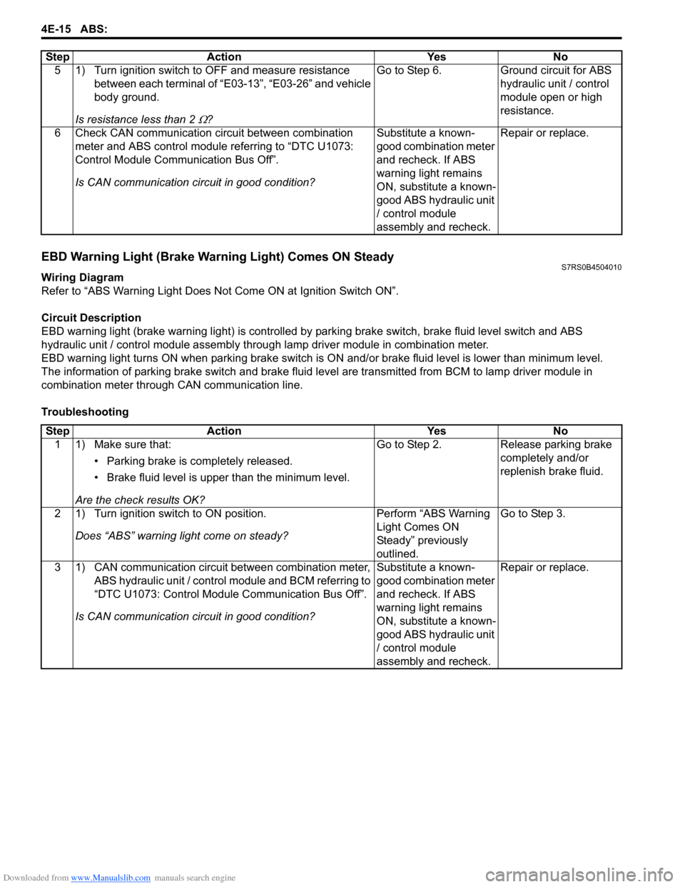
Troubleshooting 5 1) Turn ignition switch to OFF and measure resistance
between each terminal of “E03-13”, “E03-26” and vehicle
body ground.
Is resistance less than 2
Ω? Go to Step 6. Ground circuit for ABS
hydraulic unit / control
module open or high
resistance.
6 Check CAN communication circuit between combination meter and ABS control module referring to “DTC U1073:
Control Module Communication Bus Off”.
Is CAN communication circuit in good condition? Substitute a known-
good combination meter
and recheck. If ABS
warning light remains
ON, substitute a known-
good ABS hydraulic unit
/ control module
assembly and recheck.Repair or replace.
Step Action Yes No
Step
Action YesNo
1 1) Make sure that:
• Parking brake is completely released.
• Brake fluid level is upper than the minimum level.
Are the check results OK? Go to Step 2.
Release parking brake
completely and/or
replenish brake fluid.
2 1) Turn ignition switch to ON position. Does “ABS” warning light come on steady? Perform “ABS Warning
Light Comes ON
Steady” previously
outlined.Go to Step 3.
3 1) CAN communication circuit between combination meter, ABS hydraulic unit / control module and BCM referring to
“DTC U1073: Control Module Communication Bus Off”.
Is CAN communication circuit in good condition? Substitute a known-
good combination meter
and recheck. If ABS
warning light remains
ON, substitute a known-
good ABS hydraulic unit
/ control module
assembly and recheck.Repair or replace.
Page 565 of 1496
Downloaded from www.Manualslib.com manuals search engine ABS: 4E-26
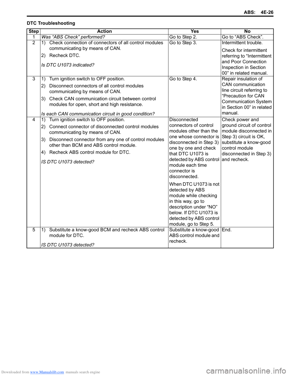
DTC TroubleshootingStep Action Yes No 1 Was “ABS Check” performed? Go to Step 2. Go to “ABS Check”.
2 1) Check connection of connectors of all control modules communicating by means of CAN.
2) Recheck DTC.
Is DTC U1073 indicated? Go to Step 3. Intermittent trouble.
Check for intermittent
referring to “Intermittent
and Poor Connection
Inspection in Section
00” in related manual.
3 1) Turn ignition switch to OFF position.
2) Disconnect connectors of all control modules communicating by means of CAN.
3) Check CAN communication circuit between control modules for open, short and high resistance.
Is each CAN communication circuit in good condition? Go to Step 4. Repair insulation of
CAN communication
line circuit referring to
“Precaution for CAN
Communication System
in Section 00” in related
manual.
4 1) Turn ignition switch to OFF position.
2) Connect connector of disconnected control modules communicating by means of CAN.
3) Disconnect connector from any one of control modules other than BCM and ABS control module.
4) Recheck ABS contro l module for DTC.
IS DTC U1073 detected? Disconnected
connectors of control
modules other than the
one whose connector is
disconnected in Step 3)
one by one and check
that DTC U1073 is
detected by ABS control
module each time
connector is
disconnected.
When DTC U1073 is not
detected by ABS
module while checking
in this way, go to
description under “NO”
below. If DTC U1073 is
detected by ABS control
module, go to Step 5.Check power and
ground circuit of control
module disconnected in
Step 3) circuit is OK,
substitute a know-good
control module
disconnected in Step 3)
and recheck.
5 1) Substitute a know-good BCM and recheck ABS control module for DTC.
IS DTC U1073 detected? Substitute a know-good
ABS control module and
recheck.
End.
Page 566 of 1496
Downloaded from www.Manualslib.com manuals search engine 4E-27 ABS:
DTC U1100: Lost Communication with ECM (Reception Error)S7RS0B4504019
Wiring Diagram
Refer to “DTC U1073: Control Module Communication Bus Off”.
DTC Detecting Condition
Reception error of communication data for ECM is detected more than specified time continuously.
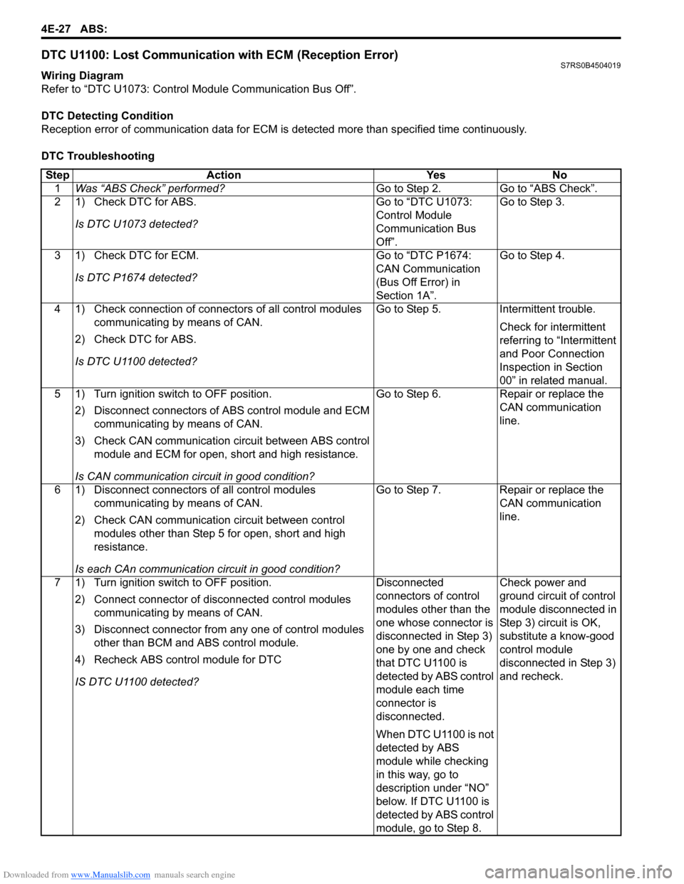
DTC Troubleshooting Step Action Yes No 1 Was “ABS Check” performed? Go to Step 2. Go to “ABS Check”.
2 1) Check DTC for ABS.
Is DTC U1073 detected? Go to “DTC U1073:
Control Module
Communication Bus
Off”.Go to Step 3.
3 1) Check DTC for ECM. Is DTC P1674 detected? Go to “DTC P1674:
CAN Communication
(Bus Off Error) in
Section 1A”.Go to Step 4.
4 1) Check connection of connectors of all control modules communicating by means of CAN.
2) Check DTC for ABS.
Is DTC U1100 detected? Go to Step 5. Intermittent trouble.
Check for intermittent
referring to “Intermittent
and Poor Connection
Inspection in Section
00” in related manual.
5 1) Turn ignition switch to OFF position.
2) Disconnect connectors of ABS control module and ECM
communicating by means of CAN.
3) Check CAN communication circuit between ABS control module and ECM for open, short and high resistance.
Is CAN communication circuit in good condition? Go to Step 6. Repair or replace the
CAN communication
line.
6 1) Disconnect connectors of all control modules communicating by means of CAN.
2) Check CAN communication circuit between control modules other than Step 5 for open, short and high
resistance.
Is each CAn communication circuit in good condition? Go to Step 7. Repair or replace the
CAN communication
line.
7 1) Turn ignition switch to OFF position. 2) Connect connector of disconnected control modules communicating by means of CAN.
3) Disconnect connector from any one of control modules other than BCM and ABS control module.
4) Recheck ABS contro l module for DTC
IS DTC U1100 detected? Disconnected
connectors of control
modules other than the
one whose connector is
disconnected in Step 3)
one by one and check
that DTC U1100 is
detected by ABS control
module each time
connector is
disconnected.
When DTC U1100 is not
detected by ABS
module while checking
in this way, go to
description under “NO”
below. If DTC U1100 is
detected by ABS control
module, go to Step 8.Check power and
ground circuit of control
module disconnected in
Step 3) circuit is OK,
substitute a know-good
control module
disconnected in Step 3)
and recheck.
Page 599 of 1496
Downloaded from www.Manualslib.com manuals search engine Electronic Stability Program: 4F-25
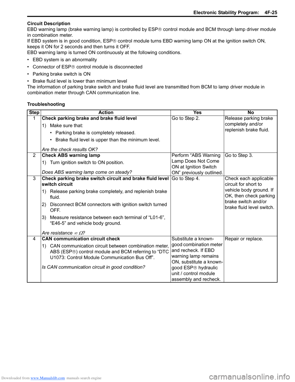
Circuit Description
EBD warning lamp (brake warning lamp) is controlled by ESP® control module and BCM through lamp driver module
in combination meter.
If EBD system is in good condition, ESP ® control module turns EBD warning lamp ON at the ignition switch ON,
keeps it ON for 2 seconds and then turns it OFF.
EBD warning lamp is turned ON cont inuously at the following conditions.
• EBD system is an abnormality
• Connector of ESP ® control module is disconnected
• Parking brake switch is ON
• Brake fluid level is lower than minimum level
The information of parking brake switch and brake fluid leve l are transmitted from BCM to lamp driver module in
combination meter through CAN communication line.
Troubleshooting
Step Action Yes No 1 Check parking brake and brake fluid level
1) Make sure that:
• Parking brake is completely released.
• Brake fluid level is upper than the minimum level.
Are the check results OK? Go to Step 2. Release parking brake
completely and/or
replenish brake fluid.
2 Check ABS warning lamp
1) Turn ignition switch to ON position.
Does ABS warning lamp come on steady? Perform “ABS Warning
Lamp Does Not Come
ON at Ignition Switch
ON” previously outlined.Go to Step 3.
3 Check parking brake switch circuit and brake fluid level
switch circuit
1) Release parking brake completely, and replenish brake
fluid.
2) Disconnect BCM connectors with ignition switch turned OFF.
3) Measure resistance between each terminal of “L01-6”, “E46-5” and vehicle body ground.
Are resistance
∞ Ω? Go to Step 4. Check each applicable
circuit for short to
vehicle body ground. If
OK, then check parking
brake switch and/or
brake fluid level switch.
4 CAN communication circuit check
1) CAN communication circuit between combination meter,
ABS (ESP® ) control module and BCM referring to “DTC
U1073: Control Module Communication Bus Off”.
Is CAN communication circuit in good condition? Substitute a known-
good combination meter
and recheck. If EBD
warning lamp remains
ON, substitute a known-
good ESP
® hydraulic
unit / control module
assembly and recheck. Repair or replace.
Page 619 of 1496
Downloaded from www.Manualslib.com manuals search engine Electronic Stability Program: 4F-45
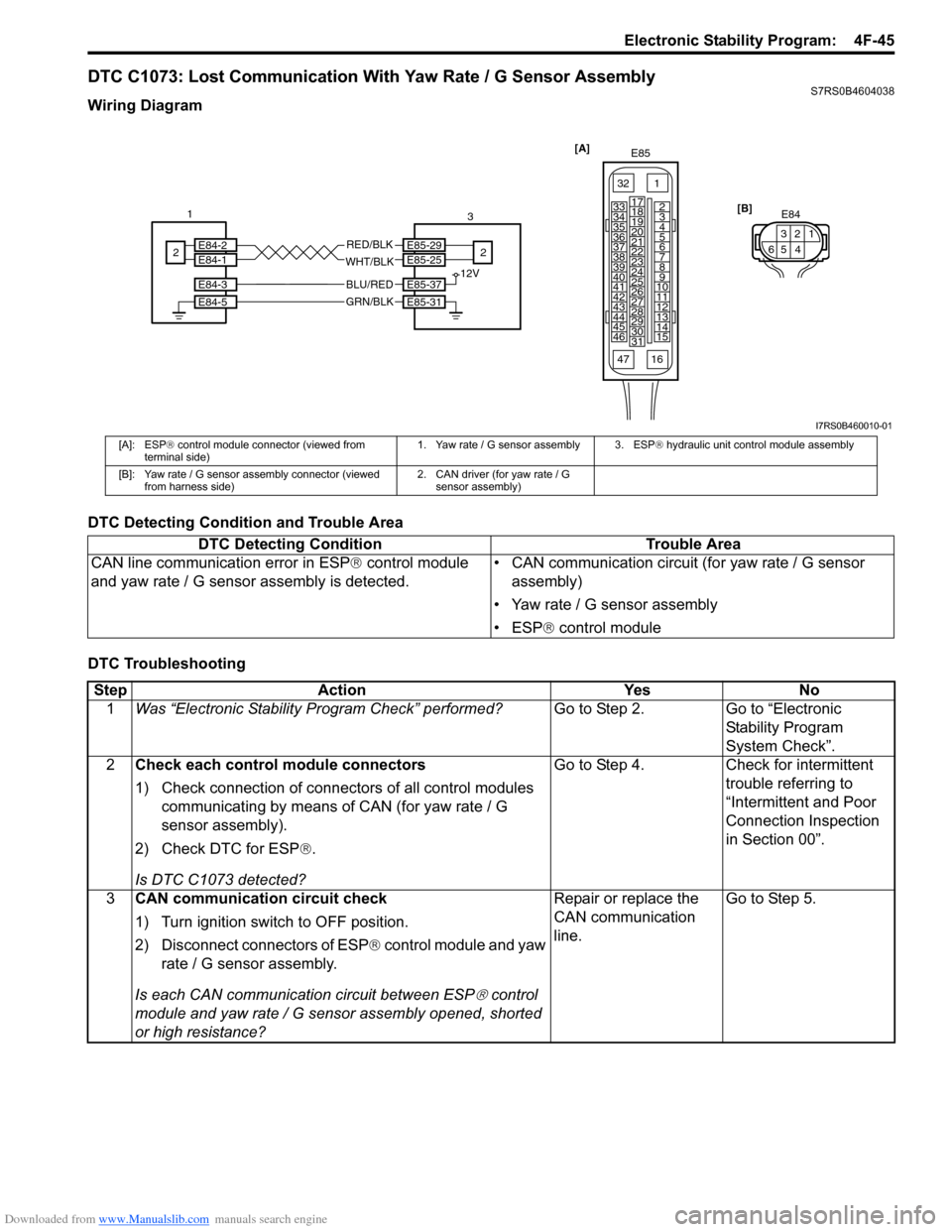
DTC C1073: Lost Communication With Yaw Rate / G Sensor AssemblyS7RS0B4604038
Wiring Diagram
DTC Detecting Condition and Trouble Area
DTC Troubleshooting
[A]E85
161
15
2
3
4
5
6
7
8
9
10
11
12
13
14
17
18
19
20
21
22
23
24
25
26
27
28
29
30
31
3233
34
35
36
37
38
39
40
41
42
43
44
45
46
47
E85-29E85-25
E85-37
E85-31
E84-3
E84-5
E84-2E84-1 12V
GRN/BLK
BLU/RED
WHT/BLK
RED/BLK [B]
E843
521
46
1
2 3
2
I7RS0B460010-01
[A]: ESP ® control module connector (viewed from
terminal side) 1. Yaw rate / G sensor assembly 3. ESP
® hydraulic unit control module assembly
[B]: Yaw rate / G sensor assembly connector (viewed from harness side) 2. CAN driver (for yaw rate / G
sensor assembly)
DTC Detecting Condition Trouble Area
CAN line communication error in ESP ® control module
and yaw rate / G sensor assembly is detected. • CAN communication circuit (for yaw rate / G sensor
assembly)
• Yaw rate / G sensor assembly
• ESP ® control module
Step Action YesNo
1 Was “Electronic Stability Pr ogram Check” performed? Go to Step 2.Go to “Electronic
Stability Program
System Check”.
2 Check each control module connectors
1) Check connection of connectors of all control modules
communicating by means of CAN (for yaw rate / G
sensor assembly).
2) Check DTC for ESP ®.
Is DTC C1073 detected? Go to Step 4.
Check for intermittent
trouble referring to
“Intermittent and Poor
Connection Inspection
in Section 00”.
3 CAN communication circuit check
1) Turn ignition switch to OFF position.
2) Disconnect connectors of ESP ® control module and yaw
rate / G sensor assembly.
Is each CAN communicati on circuit between ESP
® control
module and yaw rate / G sensor assembly opened, shorted
or high resistance? Repair or replace the
CAN communication
line.
Go to Step 5.
Page 624 of 1496
Downloaded from www.Manualslib.com manuals search engine 4F-50 Electronic Stability Program:
DTC Troubleshooting
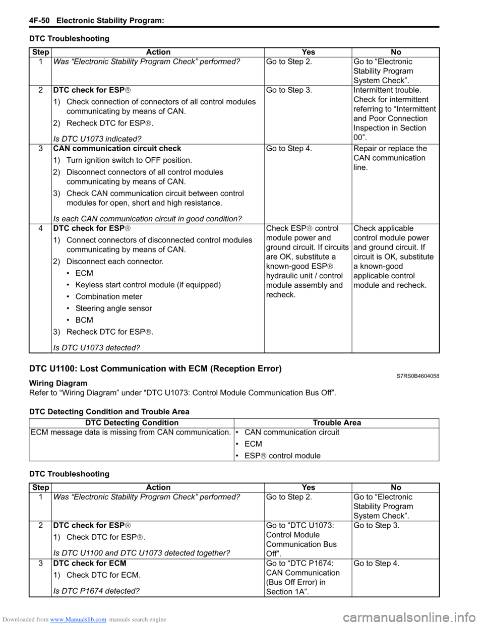
DTC U1100: Lost Communication with ECM (Reception Error)S7RS0B4604058
Wiring Diagram
Refer to “Wiring Diagram” under “DTC U1073: Control Module Communication Bus Off”.
DTC Detecting Condition and Trouble Area
DTC TroubleshootingStep Action Yes No
1 Was “Electronic Stability Pr ogram Check” performed? Go to Step 2. Go to “Electronic
Stability Program
System Check”.
2 DTC check for ESP®
1) Check connection of connectors of all control modules
communicating by means of CAN.
2) Recheck DTC for ESP ®.
Is DTC U1073 indicated? Go to Step 3. Intermittent trouble.
Check for intermittent
referring to “Intermittent
and Poor Connection
Inspection in Section
00”.
3 CAN communication circuit check
1) Turn ignition switch to OFF position.
2) Disconnect connectors of all control modules
communicating by means of CAN.
3) Check CAN communication circuit between control modules for open, short and high resistance.
Is each CAN communication circuit in good condition? Go to Step 4. Repair or replace the
CAN communication
line.
4 DTC check for ESP®
1) Connect connectors of disconnected control modules
communicating by means of CAN.
2) Disconnect each connector. •ECM
• Keyless start control module (if equipped)
• Combination meter
• Steering angle sensor
•BCM
3) Recheck DTC for ESP ®.
Is DTC U1073 detected? Check ESP
® control
module power and
ground circuit. If circuits
are OK, substitute a
known-good ESP ®
hydraulic unit / control
module assembly and
recheck. Check applicable
control module power
and ground circuit. If
circuit is OK, substitute
a known-good
applicable control
module and recheck.
DTC Detecting Condition
Trouble Area
ECM message data is missing from CAN communication. • CAN communication circuit
•ECM
• ESP® control module
Step Action YesNo
1 Was “Electronic Stability Pr ogram Check” performed? Go to Step 2.Go to “Electronic
Stability Program
System Check”.
2 DTC check for ESP®
1) Check DTC for ESP ®.
Is DTC U1100 and DTC U1073 detected together? Go to “DTC U1073:
Control Module
Communication Bus
Off”.Go to Step 3.
3 DTC check for ECM
1) Check DTC for ECM.
Is DTC P1674 detected? Go to “DTC P1674:
CAN Communication
(Bus Off Error) in
Section 1A”.Go to Step 4.
Page 625 of 1496
Downloaded from www.Manualslib.com manuals search engine Electronic Stability Program: 4F-51
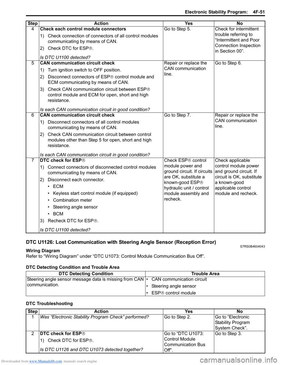
DTC U1126: Lost Communication with Steering Angle Sensor (Reception Error)S7RS0B4604043
Wiring Diagram
Refer to “Wiring Diagram” under “DTC U1073: Control Module Communication Bus Off”.
DTC Detecting Condition and Trouble Area
DTC Troubleshooting4
Check each control module connectors
1) Check connection of connectors of all control modules
communicating by means of CAN.
2) Check DTC for ESP ®.
Is DTC U1100 detected? Go to Step 5. Check for intermittent
trouble referring to
“Intermittent and Poor
Connection Inspection
in Section 00”.
5 CAN communication circuit check
1) Turn ignition switch to OFF position.
2) Disconnect connectors of ESP ® control module and
ECM communicating by means of CAN.
3) Check CAN communication circuit between ESP®
control module and ECM for open, short and high
resistance.
Is each CAN communication circuit in good condition? Repair or replace the
CAN communication
line.
Go to Step 6.
6 CAN communication circuit check
1) Disconnect connectors of all control modules
communicating by means of CAN.
2) Check CAN communication circuit between control modules other than Step 5 for open, short and high
resistance.
Is each CAN communication circuit in good condition? Go to Step 7. Repair or replace the
CAN communication
line.
7 DTC check for ESP®
1) Connect connectors of disconnected control modules
communicating by means of CAN.
2) Disconnect each connector. •ECM
• Keyless start control module (if equipped)
• Combination meter
• Steering angle sensor
•BCM
3) Recheck DTC for ESP ®.
Is DTC U1100 detected? Check ESP
® control
module power and
ground circuit. If circuits
are OK, substitute a
known-good ESP ®
hydraulic unit / control
module assembly and
recheck. Check applicable
control module power
and ground circuit. If
circuit is OK, substitute
a known-good
applicable control
module and recheck.
Step Action Yes No
DTC Detecting Condition
Trouble Area
Steering angle sensor message data is missing from CAN
communication. • CAN communication circuit
• Steering angle sensor
• ESP
® control module
Step Action YesNo
1 Was “Electronic Stability Pr ogram Check” performed? Go to Step 2.Go to “Electronic
Stability Program
System Check”.
2 DTC check for ESP®
1) Check DTC for ESP ®.
Is DTC U1126 and DTC U1073 detected together? Go to “DTC U1073:
Control Module
Communication Bus
Off”.Go to Step 3.
Page 626 of 1496
Downloaded from www.Manualslib.com manuals search engine 4F-52 Electronic Stability Program:
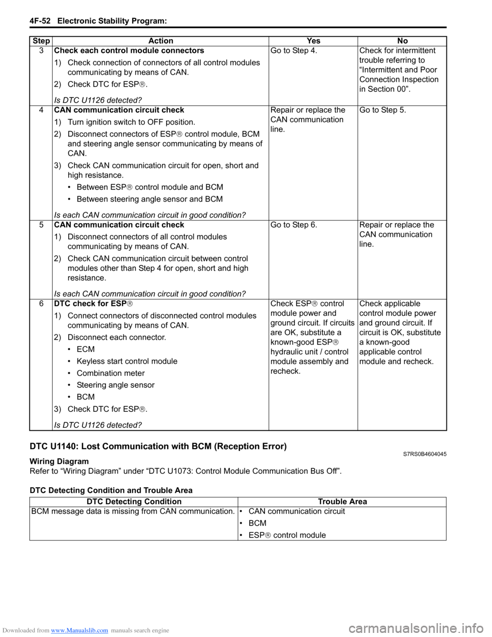
DTC U1140: Lost Communication with BCM (Reception Error)S7RS0B4604045
Wiring Diagram
Refer to “Wiring Diagram” under “DTC U1073: Control Module Communication Bus Off”.
DTC Detecting Condition and Trouble Area3
Check each control module connectors
1) Check connection of connectors of all control modules
communicating by means of CAN.
2) Check DTC for ESP ®.
Is DTC U1126 detected? Go to Step 4. Check for intermittent
trouble referring to
“Intermittent and Poor
Connection Inspection
in Section 00”.
4 CAN communication circuit check
1) Turn ignition switch to OFF position.
2) Disconnect connectors of ESP ® control module, BCM
and steering angle sensor communicating by means of
CAN.
3) Check CAN communication circuit for open, short and high resistance.
• Between ESP ® control module and BCM
• Between steering angle sensor and BCM
Is each CAN communication circuit in good condition? Repair or replace the
CAN communication
line.
Go to Step 5.
5 CAN communication circuit check
1) Disconnect connectors of all control modules
communicating by means of CAN.
2) Check CAN communication circuit between control modules other than Step 4 for open, short and high
resistance.
Is each CAN communication circuit in good condition? Go to Step 6. Repair or replace the
CAN communication
line.
6 DTC check for ESP®
1) Connect connectors of disconnected control modules
communicating by means of CAN.
2) Disconnect each connector. •ECM
• Keyless start control module
• Combination meter
• Steering angle sensor
•BCM
3) Check DTC for ESP ®.
Is DTC U1126 detected? Check ESP
® control
module power and
ground circuit. If circuits
are OK, substitute a
known-good ESP ®
hydraulic unit / control
module assembly and
recheck. Check applicable
control module power
and ground circuit. If
circuit is OK, substitute
a known-good
applicable control
module and recheck.
Step Action Yes No
DTC Detecting Condition
Trouble Area
BCM message data is missing from CAN communication. • CAN communication circuit
•BCM
• ESP® control module
Page 627 of 1496
Downloaded from www.Manualslib.com manuals search engine Electronic Stability Program: 4F-53
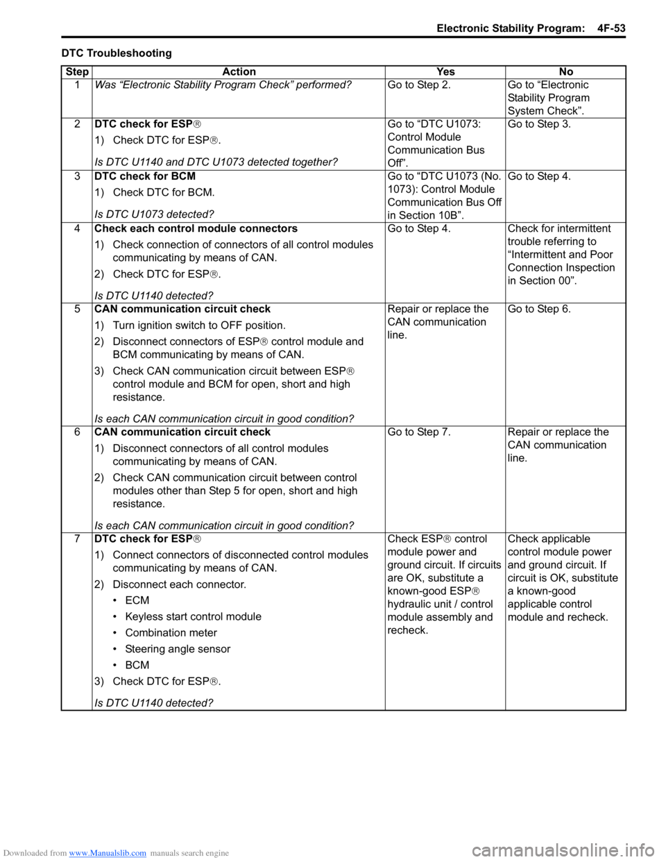
DTC TroubleshootingStep Action Yes No 1 Was “Electronic Stability Pr ogram Check” performed? Go to Step 2. Go to “Electronic
Stability Program
System Check”.
2 DTC check for ESP®
1) Check DTC for ESP ®.
Is DTC U1140 and DTC U1073 detected together? Go to “DTC U1073:
Control Module
Communication Bus
Off”.Go to Step 3.
3 DTC check for BCM
1) Check DTC for BCM.
Is DTC U1073 detected? Go to “DTC U1073 (No.
1073): Control Module
Communication Bus Off
in Section 10B”.Go to Step 4.
4 Check each control module connectors
1) Check connection of connectors of all control modules
communicating by means of CAN.
2) Check DTC for ESP ®.
Is DTC U1140 detected? Go to Step 4. Check for intermittent
trouble referring to
“Intermittent and Poor
Connection Inspection
in Section 00”.
5 CAN communication circuit check
1) Turn ignition switch to OFF position.
2) Disconnect connectors of ESP ® control module and
BCM communicating by means of CAN.
3) Check CAN communication circuit between ESP®
control module and BCM for open, short and high
resistance.
Is each CAN communication circuit in good condition? Repair or replace the
CAN communication
line.
Go to Step 6.
6 CAN communication circuit check
1) Disconnect connectors of all control modules
communicating by means of CAN.
2) Check CAN communication circuit between control modules other than Step 5 for open, short and high
resistance.
Is each CAN communication circuit in good condition? Go to Step 7. Repair or replace the
CAN communication
line.
7 DTC check for ESP®
1) Connect connectors of disconnected control modules
communicating by means of CAN.
2) Disconnect each connector. •ECM
• Keyless start control module
• Combination meter
• Steering angle sensor
•BCM
3) Check DTC for ESP ®.
Is DTC U1140 detected? Check ESP
® control
module power and
ground circuit. If circuits
are OK, substitute a
known-good ESP ®
hydraulic unit / control
module assembly and
recheck. Check applicable
control module power
and ground circuit. If
circuit is OK, substitute
a known-good
applicable control
module and recheck.