bearing SUZUKI SWIFT 2006 2.G Service Repair Manual
[x] Cancel search | Manufacturer: SUZUKI, Model Year: 2006, Model line: SWIFT, Model: SUZUKI SWIFT 2006 2.GPages: 1496, PDF Size: 34.44 MB
Page 493 of 1496
Downloaded from www.Manualslib.com manuals search engine Drive Shaft / Axle: 3A-15
Specifications
Tightening Torque SpecificationsS7RS0B3107001
NOTE
The specified tightening torque is also described in the following.
“Front Drive Shaft Assembly Components Location”
Reference:
For the tightening torque of fastener not specified in this section, refer to “Fasteners Information in Section 0A”.
Special Tools and Equipment
Recommended Service MaterialS7RS0B3108001
NOTE
Required service material is also described in the following.
“Front Drive Shaft Components”
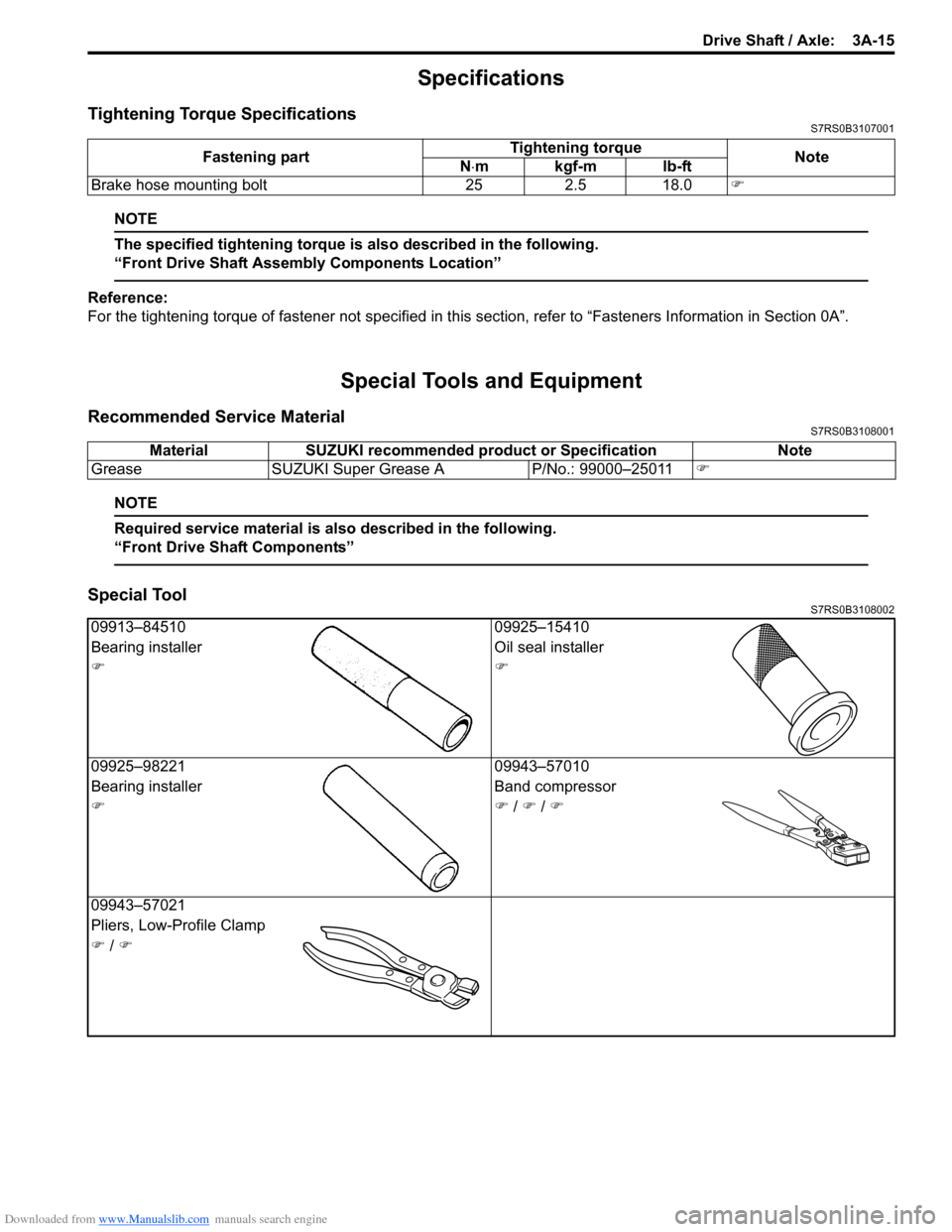
Special ToolS7RS0B3108002
Fastening part Tightening torque
Note
N ⋅mkgf-mlb-ft
Brake hose mounting bolt 25 2.5 18.0 �)
MaterialSUZUKI recommended product or Specification Note
Grease SUZUKI Super Grease A P/No.: 99000–25011�)
09913–84510 09925–15410
Bearing installer Oil seal installer
�)�)
09925–98221 09943–57010
Bearing installer Band compressor
�)�) / �) / �)
09943–57021
Pliers, Low-Profile Clamp
�) / �)
Page 504 of 1496
Downloaded from www.Manualslib.com manuals search engine 4A-6 Brake Control System and Diagnosis:
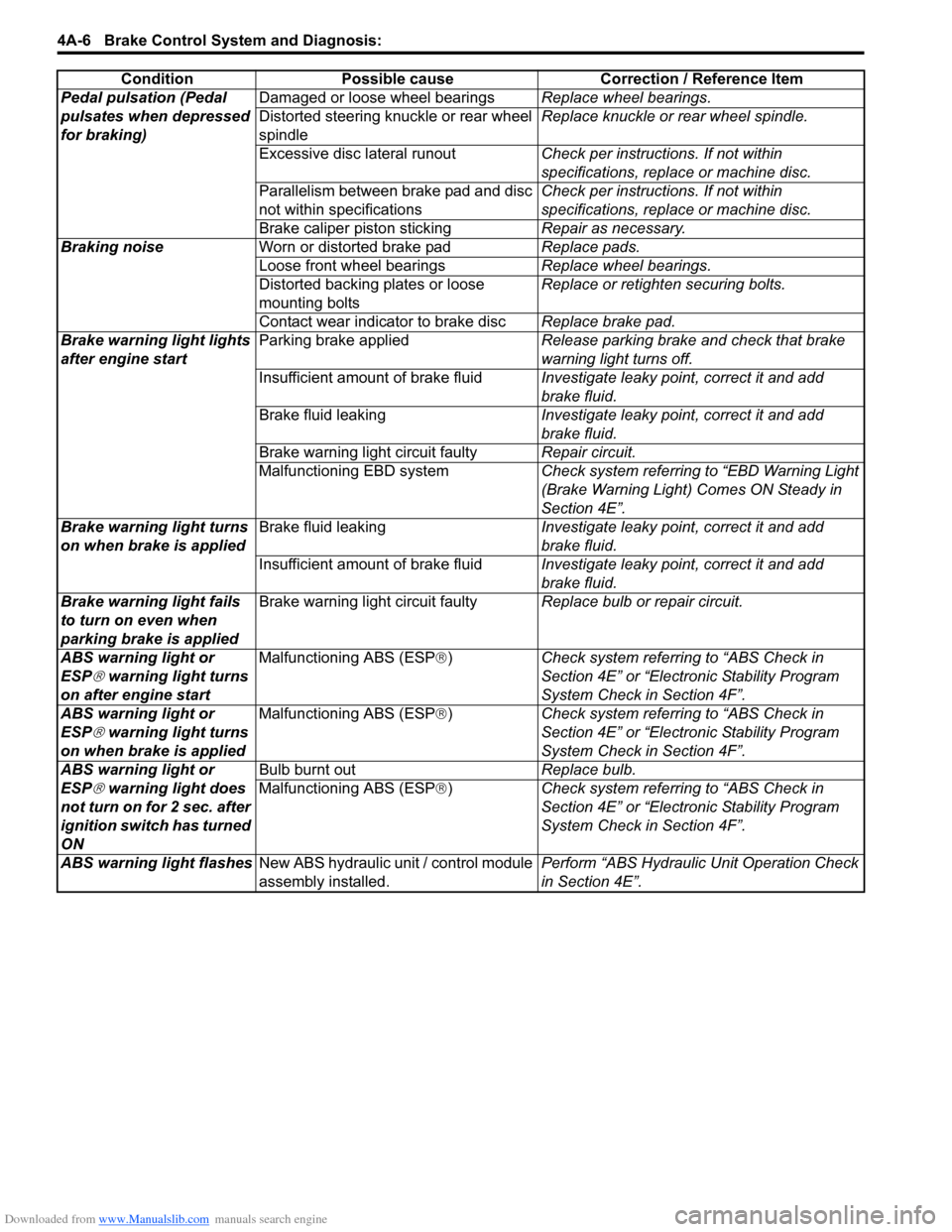
Pedal pulsation (Pedal
pulsates when depressed
for braking)Damaged or loose wheel bearings
Replace wheel bearings.
Distorted steering knuckle or rear wheel
spindle Replace knuckle or rear wheel spindle.
Excessive disc lateral runout Check per instructions. If not within
specifications, replace or machine disc.
Parallelism between brake pad and disc
not within specifications Check per instructions. If not within
specifications, replace or machine disc.
Brake caliper piston sticking Repair as necessary.
Braking noise Worn or distorted brake pad Replace pads.
Loose front wheel bearings Replace wheel bearings.
Distorted backing plates or loose
mounting bolts Replace or retighten securing bolts.
Contact wear indicator to brake disc Replace brake pad.
Brake warning light lights
after engine start Parking brake applied
Release parking brake and check that brake
warning light turns off.
Insufficient amount of brake fluid Investigate leaky point, correct it and add
brake fluid.
Brake fluid leaking Investigate leaky point, correct it and add
brake fluid.
Brake warning light circuit faulty Repair circuit.
Malfunctioning EBD system Check system referring to “EBD Warning Light
(Brake Warning Light) Comes ON Steady in
Section 4E”.
Brake warning light turns
on when brake is applied Brake fluid leaking
Investigate leaky point, correct it and add
brake fluid.
Insufficient amount of brake fluid Investigate leaky point, correct it and add
brake fluid.
Brake warning light fails
to turn on even when
parking brake is applied Brake warning light circuit faulty
Replace bulb or repair circuit.
ABS warning light or
ESP
® warning light turns
on after engine start Malfunctioning ABS (ESP
®) Check system referri ng to “ABS Check in
Section 4E” or “Electronic Stability Program
System Check in Section 4F”.
ABS warning light or
ESP
® warning light turns
on when brake is applied Malfunctioning ABS (ESP
®) Check system referri ng to “ABS Check in
Section 4E” or “Electronic Stability Program
System Check in Section 4F”.
ABS warning light or
ESP
® warning light does
not turn on for 2 sec. after
ignition switch has turned
ON Bulb burnt out
Replace bulb.
Malfunctioning ABS (ESP ®) Check system referri ng to “ABS Check in
Section 4E” or “Electronic Stability Program
System Check in Section 4F”.
ABS warning light flashes New ABS hydraulic unit / control module
assembly installed. Perform “ABS Hydraulic
Unit Operation Check
in Section 4E”.
Condition Possible cause Correction / Reference Item
Page 546 of 1496
Downloaded from www.Manualslib.com manuals search engine 4E-7 ABS:
Component Location
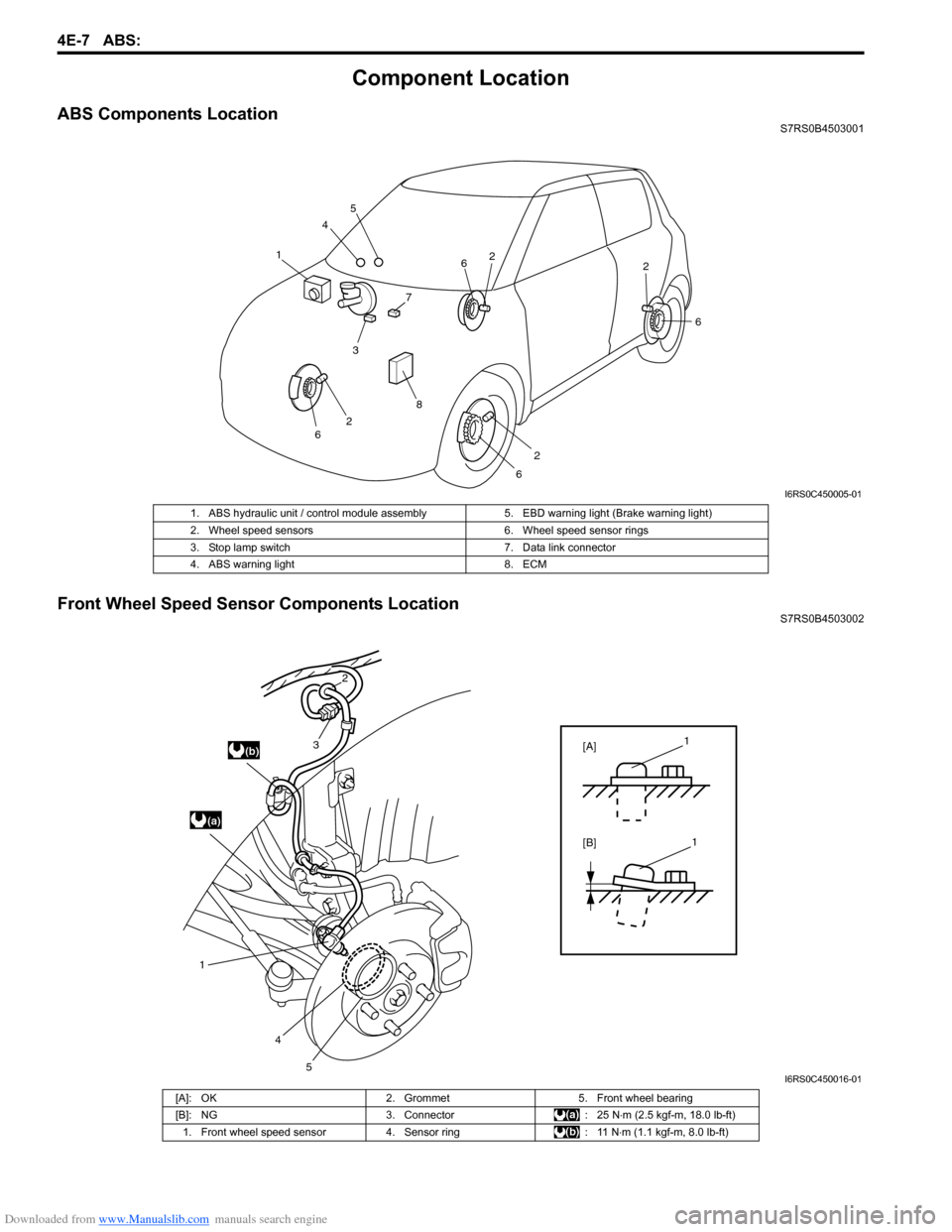
ABS Components LocationS7RS0B4503001
Front Wheel Speed Sensor Components LocationS7RS0B4503002
14
5
3
2 2
2
2
6
6
6
6
7
8
I6RS0C450005-01
1. ABS hydraulic unit / control module assembly
5. EBD warning light (Brake warning light)
2. Wheel speed sensors 6. Wheel speed sensor rings
3. Stop lamp switch 7. Data link connector
4. ABS warning light 8. ECM
[A]
[B]
1 1
2
3
4
1
(a)
(b)
5I6RS0C450016-01
[A]: OK 2. Grommet5. Front wheel bearing
[B]: NG 3. Connector: 25 N⋅m (2.5 kgf-m, 18.0 lb-ft)
1. Front wheel speed sensor 4. Sensor ring: 11 N⋅m (1.1 kgf-m, 8.0 lb-ft)
Page 558 of 1496
Downloaded from www.Manualslib.com manuals search engine 4E-19 ABS:
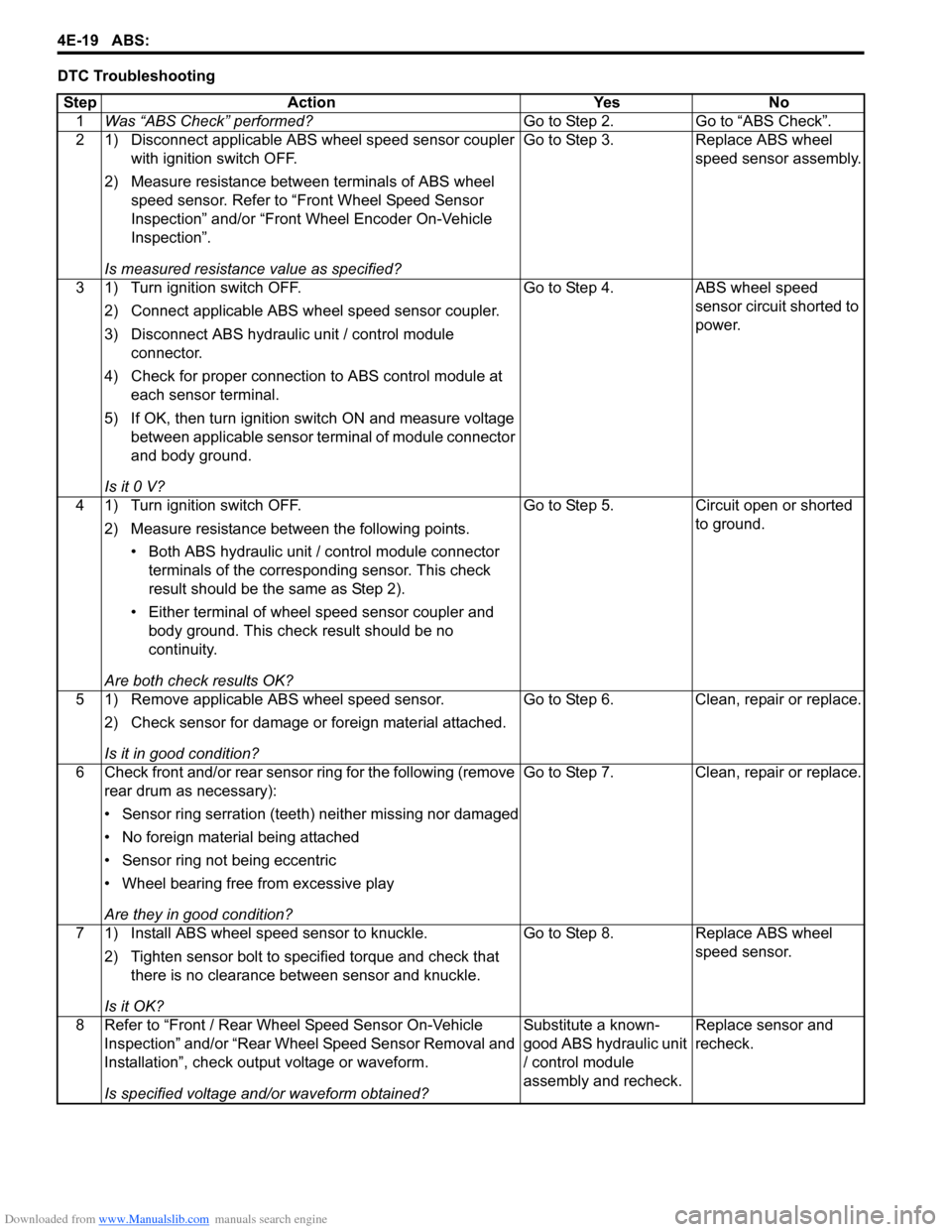
DTC TroubleshootingStep Action Yes No 1 Was “ABS Check” performed? Go to Step 2. Go to “ABS Check”.
2 1) Disconnect applicable ABS wheel speed sensor coupler with ignition switch OFF.
2) Measure resistance betw een terminals of ABS wheel
speed sensor. Refer to “Front Wheel Speed Sensor
Inspection” and/or “Front Wheel Encoder On-Vehicle
Inspection”.
Is measured resistance value as specified? Go to Step 3. Replace ABS wheel
speed sensor assembly.
3 1) Turn ignition switch OFF. 2) Connect applicable ABS wh eel speed sensor coupler.
3) Disconnect ABS hydraulic unit / control module connector.
4) Check for proper connection to ABS control module at each sensor terminal.
5) If OK, then turn ignition switch ON and measure voltage between applicable sensor terminal of module connector
and body ground.
Is it 0 V? Go to Step 4. ABS wheel speed
sensor circuit shorted to
power.
4 1) Turn ignition switch OFF. 2) Measure resistance between the following points.• Both ABS hydraulic unit / control module connector terminals of the correspo nding sensor. This check
result should be the same as Step 2).
• Either terminal of wheel speed sensor coupler and body ground. This check result should be no
continuity.
Are both check results OK? Go to Step 5. Circuit open or shorted
to ground.
5 1) Remove applicable ABS wheel speed sensor. 2) Check sensor for damage or foreign material attached.
Is it in good condition? Go to Step 6. Clean, repair or replace.
6 Check front and/or rear sensor ring for the following (remove rear drum as necessary):
• Sensor ring serration (teeth) neither missing nor damaged
• No foreign material being attached
• Sensor ring not being eccentric
• Wheel bearing free from excessive play
Are they in good condition? Go to Step 7. Clean, repair or replace.
7 1) Install ABS wheel speed sensor to knuckle. 2) Tighten sensor bolt to specified torque and check that there is no clearance between sensor and knuckle.
Is it OK? Go to Step 8. Replace ABS wheel
speed sensor.
8 Refer to “Front / Rear Wheel Speed Sensor On-Vehicle Inspection” and/or “Rear Wheel Speed Sensor Removal and
Installation”, check output voltage or waveform.
Is specified voltage and/or waveform obtained? Substitute a known-
good ABS hydraulic unit
/ control module
assembly and recheck.
Replace sensor and
recheck.
Page 573 of 1496
Downloaded from www.Manualslib.com manuals search engine ABS: 4E-34
Rear Wheel Speed Sensor InspectionS7RS0B4506009
Refer to “Front Wheel Speed Sensor Inspection” since
rear wheel speed sensor is the same as front wheel
speed sensor.
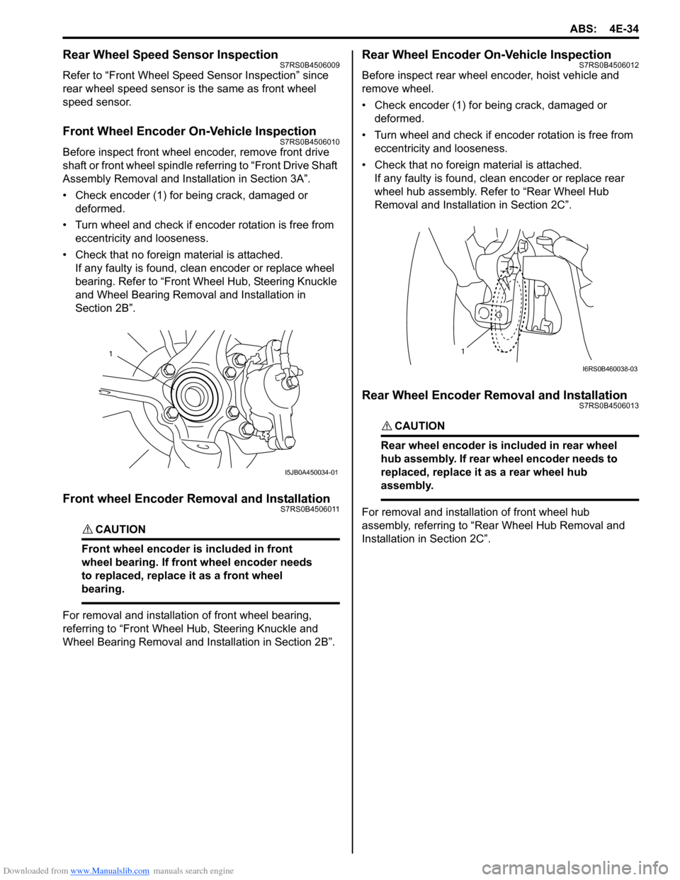
Front Wheel Encoder On-Vehicle InspectionS7RS0B4506010
Before inspect front wheel encoder, remove front drive
shaft or front wheel spindle referring to “Front Drive Shaft
Assembly Removal and Installation in Section 3A”.
• Check encoder (1) for being crack, damaged or deformed.
• Turn wheel and check if encoder rotation is free from eccentricity and looseness.
• Check that no foreign material is attached. If any faulty is found, cl ean encoder or replace wheel
bearing. Refer to “Front Wheel Hub, Steering Knuckle
and Wheel Bearing Removal and Installation in
Section 2B”.
Front wheel Encoder Removal and InstallationS7RS0B4506011
CAUTION!
Front wheel encoder is included in front
wheel bearing. If front wheel encoder needs
to replaced, replace it as a front wheel
bearing.
For removal and installation of front wheel bearing,
referring to “Front Wheel Hub, Steering Knuckle and
Wheel Bearing Removal and Installation in Section 2B”.
Rear Wheel Encoder On-Vehicle InspectionS7RS0B4506012
Before inspect rear wheel encoder, hoist vehicle and
remove wheel.
• Check encoder (1) for being crack, damaged or deformed.
• Turn wheel and check if encoder rotation is free from eccentricity and looseness.
• Check that no foreign material is attached. If any faulty is found, clean encoder or replace rear
wheel hub assembly. Refer to “Rear Wheel Hub
Removal and Installati on in Section 2C”.
Rear Wheel Encoder Removal and InstallationS7RS0B4506013
CAUTION!
Rear wheel encoder is included in rear wheel
hub assembly. If rear wheel encoder needs to
replaced, replace it as a rear wheel hub
assembly.
For removal and installation of front wheel hub
assembly, referring to “Rear Wheel Hub Removal and
Installation in Section 2C”.
1
I5JB0A450034-01
1
I6RS0B460038-03
Page 607 of 1496
Downloaded from www.Manualslib.com manuals search engine Electronic Stability Program: 4F-33
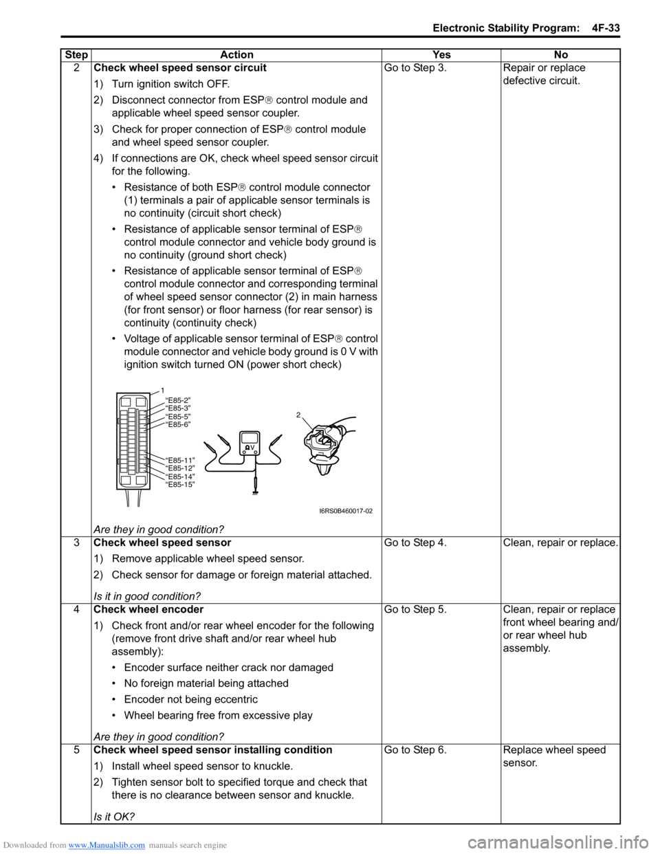
2Check wheel speed sensor circuit
1) Turn ignition switch OFF.
2) Disconnect connector from ESP ® control module and
applicable wheel speed sensor coupler.
3) Check for proper connection of ESP ® control module
and wheel speed sensor coupler.
4) If connections are OK, che ck wheel speed sensor circuit
for the following.
• Resistance of both ESP ® control module connector
(1) terminals a pair of app licable sensor terminals is
no continuity (circuit short check)
• Resistance of applicable sensor terminal of ESP ®
control module connector and vehicle body ground is
no continuity (ground short check)
• Resistance of applicable sensor terminal of ESP ®
control module connector and corresponding terminal
of wheel speed sensor connector (2) in main harness
(for front sensor) or floor harness (for rear sensor) is
continuity (continuity check)
• Voltage of applicable sensor terminal of ESP ® control
module connector and vehicle body ground is 0 V with
ignition switch turned ON (power short check)
Are they in good condition? Go to Step 3. Repair or replace
defective circuit.
3 Check wheel speed sensor
1) Remove applicable wheel speed sensor.
2) Check sensor for damage or foreign material attached.
Is it in good condition? Go to Step 4. Clean, repair or replace.
4 Check wheel encoder
1) Check front and/or rear wheel encoder for the following
(remove front drive shaft and/or rear wheel hub
assembly):
• Encoder surface neither crack nor damaged
• No foreign material being attached
• Encoder not being eccentric
• Wheel bearing free from excessive play
Are they in good condition? Go to Step 5. Clean, repair or replace
front wheel bearing and/
or rear wheel hub
assembly.
5 Check wheel speed sensor installing condition
1) Install wheel speed sensor to knuckle.
2) Tighten sensor bolt to specified torque and check that
there is no clearance between sensor and knuckle.
Is it OK? Go to Step 6. Replace wheel speed
sensor.
Step Action Yes No
1
2“E85-2”“E85-3”“E85-5”
“E85-6”
“E85-11”
“E85-12”
“E85-14”
“E85-15”
I6RS0B460017-02
Page 635 of 1496
Downloaded from www.Manualslib.com manuals search engine Electronic Stability Program: 4F-61
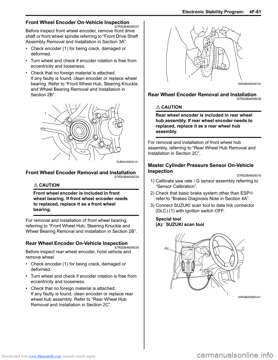
Front Wheel Encoder On-Vehicle InspectionS7RS0B4606033
Before inspect front wheel encoder, remove front drive
shaft or front wheel spindle referring to “Front Drive Shaft
Assembly Removal and Installation in Section 3A”.
• Check encoder (1) for being crack, damaged or deformed.
• Turn wheel and check if encoder rotation is free from eccentricity and looseness.
• Check that no foreign material is attached. If any faulty is found, cl ean encoder or replace wheel
bearing. Refer to “Front Wheel Hub, Steering Knuckle
and Wheel Bearing Removal and Installation in
Section 2B”.
Front Wheel Encoder Removal and InstallationS7RS0B4606034
CAUTION!
Front wheel encoder is included in front
wheel bearing. If front wheel encoder needs
to replaced, replace it as a front wheel
bearing.
For removal and installation of front wheel bearing,
referring to “Front Wheel Hub, Steering Knuckle and
Wheel Bearing Removal and Installation in Section 2B”.
Rear Wheel Encoder On-Vehicle InspectionS7RS0B4606035
Before inspect rear wheel encoder, hoist vehicle and
remove wheel.
• Check encoder (1) for being crack, damaged or deformed.
• Turn wheel and check if encoder rotation is free from eccentricity and looseness.
• Check that no foreign material is attached. If any faulty is found, cl ean encoder or replace rear
wheel hub assembly. Refer to “Rear Wheel Hub
Removal and Installati on in Section 2C”.
Rear Wheel Encoder Removal and InstallationS7RS0B4606036
CAUTION!
Rear wheel encoder is included in rear wheel
hub assembly. If rear wheel encoder needs to
replaced, replace it as a rear wheel hub
assembly.
For removal and installation of front wheel hub
assembly, referring to “Rear Wheel Hub Removal and
Installation in Section 2C”.
Master Cylinder Pressure Sensor On-Vehicle
Inspection
S7RS0B4606016
1) Calibrate yaw rate / G sens or assembly referring to
“Sensor Calibration”.
2) Check that basic brake system other than ESP ®
refer to “Brakes Diagnosi s Note in Section 4A”.
3) Connect SUZUKI scan tool to data link connector (DLC) (1) with ignition switch OFF.
Special tool
(A): SUZUKI scan tool
1
I5JB0A450034-01
1
I6RS0B460038-03
(A)
1
I4RS0B450003-01
Page 646 of 1496
Downloaded from www.Manualslib.com manuals search engine 5A-2 Automatic Transmission/Transaxle:
CAUTION!
• Keep component parts in group for each subassembly and avoid mixing them up.
• Clean all parts with cleaning solvent thoroughly and air dry them.
• Use kerosene or automatic transaxle fluid as cleaning solvent.
• Do not use wiping cloths or rags to clean or dry parts.
• All oil passages should be blown out and checked to make sure that they are not
obstructed.
• Keep face and eyes away from solvent spray while air blowing parts.
• Check mating surface for irregularities and remove them, if any, and clean it again.
• Soak new clutch discs and brake discs in transaxle fluid for at least 2 hours before
assembly.
• Replace all gaskets and O-ring with new ones.
• Apply automatic transaxle fluid to all O- rings.
• When installing seal ring, be careful so that it is not expanded excessively, extruded or
caught.
• Replace oil seals that are removed and apply grease to their lips.
• Before installing, be sure to apply automatic transaxle fluid to sliding, rolling
and thrusting surface of all component
part. Also after installation, make sure to
check each part for proper operation.
• Always use torque wrench when tightening bolts.
• A new discs should be soaked in ATF at least 2 hours before use.
Part Inspection and Correction Table Part Inspect for Correction
Casted part,
machined part Small flaw, burr
Remove with oil
stone.
Deep or grooved
flaw Replace part.
Clogged fluid
passage Clean with air or
wire.
Flaw on installing
surface, residual
gasket Remove with oil
stone or replace
part.
Crack Replace part.
Bearing Unsmooth rotation Replace.
Streak, pitting, flaw,
crack
Replace.
Bushing, thrust
washer Flaw, burr, wear,
burning
Replace.
Oil seal, gasket Flawed or
hardened seal ring
Replace.
Worn seal ring on
its periphery or side Replace.
Piston seal ring, oil
seal, gasket, etc. Replace.
Gear Flaw, burr Replace.
Worn gear tooth Replace.
Splined part Burr, flaw, torsion Correct with oil
stone or replace.
Snap ring Wear, flaw,
distortion
Replace.
No interference Replace.
Thread Burr Replace.
Damage Replace.
Sp rin g Settling, sign of
burning Replace.
Friction plate Wear, burning,
distortion,
damaged claw Replace.
Separator plate,
retaining plate Wear, burning,
distortion,
damaged claw
Replace.
Sealing surface
(where lip
contacts) Flaw, rough
surface, stepped
wear, foreign
material
Replace.
Page 753 of 1496
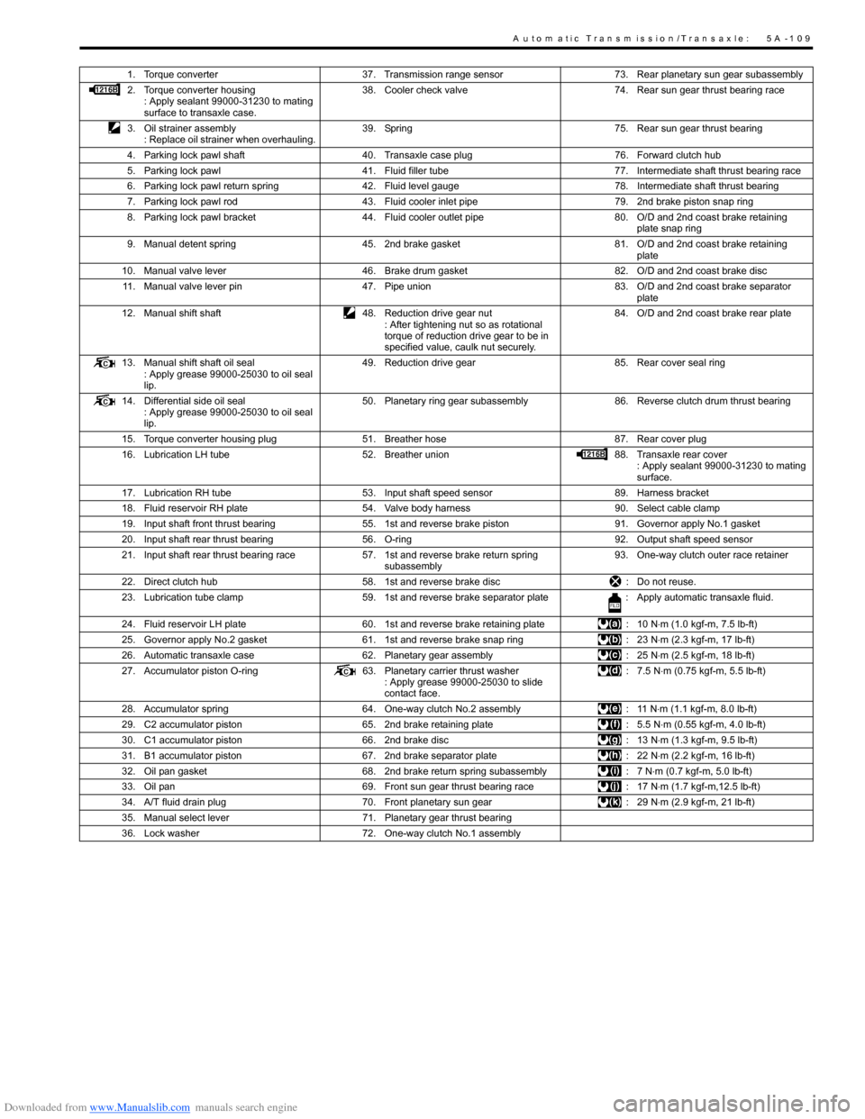
Downloaded from www.Manualslib.com manuals search engine A u to m a tic Tra n s m is s io n /Tra n s a x le : 5 A -1 0 9
1. Torque converter37. Transmission range sensor 73. Rear planetary sun gear subassembly
2. Torque converter housing : Apply sealant 99000-31230 to mating
surface to transaxle case. 38. Cooler check valve
74. Rear sun gear thrust bearing race
3. Oil strainer assembly : Replace oil strainer when overhauling. 39. Spring
75. Rear sun gear thrust bearing
4. Parking lock pawl shaft 40. Transaxle case plug 76. Forward clutch hub
5. Parking lock pawl 41. Fluid filler tube 77. Intermediate shaft thrust bearing race
6. Parking lock pawl return spring 42. Fluid level gauge 78. Intermediate shaft thrust bearing
7. Parking lock pawl rod 43. Fluid cooler inlet pipe 79. 2nd brake piston snap ring
8. Parking lock pawl bracket 44. Fluid cooler outlet pipe 80. O/D and 2nd coast brake retaining
plate snap ring
9. Manual detent spring 45. 2nd brake gasket 81. O/D and 2nd coast brake retaining
plate
10. Manual valve lever 46. Brake drum gasket 82. O/D and 2nd coast brake disc
11. Manual valve lever pin 47. Pipe union 83. O/D and 2nd coast brake separator
plate
12. Manual shift shaft 48. Reduction drive gear nut
: After tightening nut so as rotational
torque of reduction drive gear to be in
specified value, caulk nut securely. 84. O/D and 2nd coast brake rear plate
13. Manual shift shaft oil seal : Apply grease 99000-25030 to oil seal
lip. 49. Reduction drive gear
85. Rear cover seal ring
14. Differential side oil seal : Apply grease 99000-25030 to oil seal
lip. 50. Planetary ring gear subassembly
86. Reverse clutch drum thrust bearing
15. Torque converter housing plug 51. Breather hose 87. Rear cover plug
16. Lubrication LH tube 52. Breather union 88. Transaxle rear cover
: Apply sealant 99000-31230 to mating
surface.
17. Lubrication RH tube 53. Input shaft speed sensor 89. Harness bracket
18. Fluid reservoir RH plate 54. Valve body harness 90. Select cable clamp
19. Input shaft front thrust bearing 55. 1st and reverse brake piston 91. Governor apply No.1 gasket
20. Input shaft rear thrust bearing 56. O-ring 92. Output shaft speed sensor
21. Input shaft rear thrust bearing race 57. 1st and reverse brake return spring
subassembly 93. One-way clutch outer race retainer
22. Direct clutch hub 58. 1st and reverse brake disc : Do not reuse.
23. Lubrication tube clamp 59. 1st and reverse brake separator plate : Apply automatic transaxle fluid.
24. Fluid reservoir LH plate 60. 1st and reverse brake retaining plate : 10 N⋅m (1.0 kgf-m, 7.5 lb-ft)
25. Governor apply No.2 gasket 61. 1st and reverse brake snap ring : 23 N⋅m (2.3 kgf-m, 17 lb-ft)
26. Automatic transaxle case 62. Planetary gear assembly : 25 N⋅m (2.5 kgf-m, 18 lb-ft)
27. Accumulator piston O-ring 63. Planetary carrier thrust washer
: Apply grease 99000-25030 to slide
contact face. : 7.5 N
⋅m (0.75 kgf-m, 5.5 lb-ft)
28. Accumulator spring 64. One-way clutch No.2 assembly : 11 N⋅m (1.1 kgf-m, 8.0 lb-ft)
29. C2 accumulator piston 65. 2nd brake retaining plate : 5.5 N⋅m (0.55 kgf-m, 4.0 lb-ft)
30. C1 accumulator piston 66. 2nd brake disc : 13 N⋅m (1.3 kgf-m, 9.5 lb-ft)
31. B1 accumulator piston 67. 2nd brake separator plate : 22 N⋅m (2.2 kgf-m, 16 lb-ft)
32. Oil pan gasket 68. 2nd brake return spring subassembly : 7 N⋅m (0.7 kgf-m, 5.0 lb-ft)
33. Oil pan 69. Front sun gear thrust bearing race : 17 N⋅m (1.7 kgf-m,12.5 lb-ft)
34. A/T fluid drain plug 70. Front planetary sun gear : 29 N⋅m (2.9 kgf-m, 21 lb-ft)
35. Manual select lever 71. Planetary gear thrust bearing
36. Lock washer 72. One-way clutch No.1 assembly
Page 757 of 1496

Downloaded from www.Manualslib.com manuals search engine Automatic Transmission/Transaxle: 5A-113
19) Remove transaxle case plug (1).
20) Remove torque converter housing bolts.
21) Remove torque converter housing (1) while tapping
around it lightly with plastic hammer.
22) Remove breather hose (1).
23) Remove breather union (2).
24) Measure input shaft thrust play. Apply dial gauge onto input shaft end (1) and
measure thrust play of input shaft.
When input shaft thrust play is out of specification,
select input shaft front th rust bearing with proper
thickness from among the list below and replace it.
Special tool
(A): 09900–20607
(B): 09900-20701
Input shaft thrust play
0.3 – 0.9 mm (0.012 – 0.035 in.)
Available input shaft front thrust bearing
thickness
: 3.45, 4.05 mm (0.136, 0.159 in.) 25) Remove oil pump assembly (1).
26) Remove direct clutch assembly (1).
27) Remove input shaft front thrust bearing (1).
NOTE
If input shaft front thrust bearing is not
found, it may have been taken out with oil
pump assembly.
I2RH0B510095-01
I3RM0B510060-01
1
2
I2RH0B510097-01
I2RH0B510098-01
I2RH0B510099-01
I2RH0B510100-01
I2RH0B510101-01