4F-1 SUZUKI SWIFT 2006 2.G Service Workshop Manual
[x] Cancel search | Manufacturer: SUZUKI, Model Year: 2006, Model line: SWIFT, Model: SUZUKI SWIFT 2006 2.GPages: 1496, PDF Size: 34.44 MB
Page 4 of 1496

Downloaded from www.Manualslib.com manuals search engine 00
0
1
2
3
4
5
6
7
8
9
10
11
Vo l u m e 1
Precautions............................................................... 00-iPrecautions ............................................................ 00-1
General Information ................ ................................... 0-i
General Information ............................................... 0A-1
Maintenance and Lubricatio n ................................. 0B-1
Engine ......................................................................... 1-i Precautions .............................................................. 1-1
Engine General Information and Diagnosis ........... 1A-1
Aux. Emission Control Devices .............................. 1B-1
Engine Electrical Devices....................................... 1C-1
Engine Mechanical ................................................. 1D-1
Engine Lubrication System .................................... 1E-1
Engine Cooling System .......................................... 1F-1
Fuel System ...........................................................1G-1
Ignition System....................................................... 1H-1
Starting System ....................................................... 1I-1
Charging System.....................................................1J-1
Exhaust System ..................................................... 1K-1
Suspension ................................................................. 2-i Precautions .............................................................. 2-1
Suspension General Diagnosis .............................. 2A-1
Front Suspension ................................................... 2B-1
Rear Suspension................ .................................... 2C-1
Wheels and Tires ................................................... 2D-1
Driveline / Axle ........................................................... 3-i Precautions .............................................................. 3-1
Drive Shaft / Axle ................................................... 3A-1
Brakes ......................................................................... 4-i Precautions .............................................................. 4-1
Brake Control System and Diagnosis .................... 4A-1
Front Brakes........................................................... 4B-1
Rear Brakes ........................................................... 4C-1
Parking Brake......................................................... 4D-1
ABS ........................................................................ 4E-1
Electronic Stability Program ................................... 4F-1
Vo l u m e 2
Precautions ............................................................... 00-iPrecautions ............................................................ 00-1
Transmission / Transaxle .... ...................................... 5-i
Precautions .............................................................. 5-1
Automatic Transmission/Transaxle ........................ 5A-1
Manual Transmission/Transaxle ............................ 5B-1
Clutch .....................................................................5C-1
Steering ....................................................................... 6-i Precautions .............................................................. 6-1
Steering General Diagnosis ................................... 6A-1
Steering Wheel and Column .................................. 6B-1
Power Assisted Steering System ...........................6C-1
HVAC ........................................................................... 7-i Precautions .............................................................. 7-1
Heater and Ventilation............................................ 7A-1
Air Conditioning System ......................................... 7B-1
Restraint ...................................................................... 8-i Precautions .............................................................. 8-1
Seat Belts ............................................................... 8A-1
Air Bag System ...................................................... 8B-1
Body, Cab and Accessories .... .................................. 9-i
Precautions .............................................................. 9-1
Wiring Systems ...................................................... 9A-1
Lighting Systems .................................................... 9B-1
Instrumentation / Driver Info. / Horn .......................9C-1
Wipers / Washers ...................................................9D-1
Glass / Windows / Mirrors ...................................... 9E-1
Security and Locks ................................................. 9F-1
Seats ..................................................................... 9G-1
Interior Trim ............................................................9H-1
Hood / Fenders / Doors .......................................... 9J-1
Body Structure ....................................................... 9K-1
Paint / Coatings ...................................................... 9L-1
Exterior Trim .......................................................... 9M-1
Control Systems ....................................................... 10-i Precautions ............................................................ 10-1
Body Electrical Control Sy stem ............................ 10B-1
Immobilizer Control System .................................10C-1
Keyless Start System ........................................... 10E-1
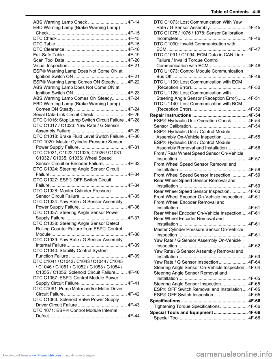
TABLE OF CONTENTS
Page 496 of 1496

Downloaded from www.Manualslib.com manuals search engine 4-ii Table of Contents
Repair Instructions ..............................................4D-2Parking Brake Inspection and Adjustment ..........4D-2
Parking Brake Cable Removal and Installation ......................................................... 4D-3
Parking Brake Lever Removal and Installation ....4D-3
Specifications .... ...................................................4D-4
Tightening Torque Specifications ........................4D-4
ABS ........................................... .................4E-1
Precautions........................................................... 4E-1
Precautions in Diagnosing Troubles ................... 4E-1
Precautions in On-Vehicle Service...................... 4E-1
Precautions in Hydraulic Unit Operation Check ................................................................ 4E-1
General Description ............................................. 4E-2 ABS Description .................................................. 4E-2
ABS Hydraulic Unit / Control Module Assembly Description ....................................... 4E-2
CAN Communication System Description........... 4E-3
Schematic and Routing Diagram ........................ 4E-4 ABS Schematic ................................................... 4E-4
ABS Wiring Circuit Diagram ................................ 4E-5
Component Location ........... ................................ 4E-7
ABS Components Location ................................. 4E-7
Front Wheel Speed Sensor Components Location ............................................................ 4E-7
Rear Wheel Speed Sensor Components Location ............................................................ 4E-8
Diagnostic Information and Procedures ............ 4E-8 ABS Check .......................................................... 4E-8
ABS Warning Light Check................................. 4E-10
EBD Warning Light (Brake Warning Light) Check .............................................................. 4E-10
DTC Check........................................................ 4E-11
DTC Table ......................................................... 4E-11
DTC Clearance ................................................. 4E-12
Scan Tool Data ................................................. 4E-12
ABS Warning Light Does Not Come ON at Ignition Switch ON .......................................... 4E-13
ABS Warning Light Comes ON Steady ............. 4E-14
EBD Warning Light (Brake Warning Light) Comes ON Steady .......................................... 4E-15
Serial Data Link Circuit Check .......................... 4E-16
DTC C1021, C1022 / C1025, C1026 / C1031, C1032 / C1035, C1036: Right-Front / Left-
Front / Right-Rear / Left-Rear Wheel Speed
Sensor Circuit or Sensor Ring ........................ 4E-18
DTC C1041 / C1045 / C1051 / C1055, DTC C1042 / C1046 / C1052 / C1056: Right-Front
/ Left-Front / Right-Rear / Left-Rear Inlet
Solenoid Circuit, Right-Front / Left-Front /
Right-Rear / Left-Rear Outlet Solenoid
Circuit .............................................................. 4E-20
DTC C1057: Power Source Circuit ................... 4E-21
DTC C1061: ABS Pump Motor and/or Motor Driver Circuit ................................................... 4E-22
DTC C1063: Solenoid Valve Power Supply Driver Circuit ................................................... 4E-23
DTC C1071: ABS Control Module..................... 4E-24 DTC U1073: Control Module Communication
Bus Off ............................................................ 4E-25
DTC U1100: Lost Communication with ECM (Reception Error)............................................. 4E-27
Repair Instructions ............ ................................ 4E-28
ABS Hydraulic Unit Operati on Check................ 4E-28
ABS Hydraulic Unit / Control Module
Assembly Components ...... ............................. 4E-29
ABS Hydraulic Unit / Control Module
Assembly On-Vehicle Inspection .................... 4E-29
ABS Hydraulic Unit / Control Module
Assembly Removal and Inst allation ................ 4E-29
Front / Rear Wheel Speed Sensor On-Vehicle Inspection ........................................................ 4E-31
Front Wheel Speed Sensor Removal and Installation ....................................................... 4E-32
Front Wheel Speed Sensor Inspection ............. 4E-32
Rear Wheel Speed Sensor Removal and Installation ....................................................... 4E-33
Rear Wheel Speed Sensor Inspection .............. 4E-34
Front Wheel Encoder On-Veh icle Inspection .... 4E-34
Front wheel Enco der Removal and
Installation ....................................................... 4E-34
Rear Wheel Encoder On-Veh icle Inspection..... 4E-34
Rear Wheel Encoder Removal and Installation ....................................................... 4E-34
Specifications ..................... ................................ 4E-35
Tightening Torque Specifications ...................... 4E-35
Special Tools and Equipmen t ........................... 4E-35
Special Tool ...................................................... 4E-35
Electronic Stability Prog ram ...................4F-1
Precautions ........................................................... 4F-1
Precautions in Diagnosing Troubles ................... 4F-1
Precautions in On-Vehicle Service...................... 4F-1
Precautions in Hydraulic Unit Operation Check ................................................................ 4F-1
Precautions in Sensor Calibration ....................... 4F-1
Precautions in Speedometer Test or Other Tests ................................................................. 4F-2
General Description ............................................. 4F-2 Electronic Stability Program Description ............. 4F-2
Electronic Stability Program Construction ........... 4F-3
ESP® Hydraulic Unit / Control Module
Assembly Description........................................ 4F-5
Warning Lamp, Indicator Lamp Description ........ 4F-6
CAN Communication System Description........... 4F-6
CAN Communication System For Electronic Stability Program Description ............................ 4F-7
Schematic and Routing Diagram ........................ 4F-8 Electronic Stability Program Schematic .............. 4F-8
Electronic Stability Program Wiring Circuit Diagram............................................................. 4F-9
Component Location ............ ............................. 4F-11
Electronic Stability Program Component
Location........................................................... 4F-11
Diagnostic Information and Procedures .......... 4F-12 Electronic Stability Program System Check ...... 4F-12
ESP® Warning lamp Check .............................. 4F-14
Page 497 of 1496
Downloaded from www.Manualslib.com manuals search engine Table of Contents 4-iii
ABS Warning Lamp Check ............................... 4F-14
EBD Warning Lamp (Brake Warning Lamp) Check .............................................................. 4F-15
DTC Check ....................................................... 4F-15
DTC Table ......................................................... 4F-15
DTC Clearance ................................................. 4F-18
Fail-Safe Table ................ .................................. 4F-19
Scan Tool Data ................................................. 4F-20
Visual Inspection ............................................... 4F-21
ESP ® Warning Lamp Does Not Come ON at
Ignition Switch ON .......................................... 4F-21
ESP ® Warning Lamp Comes ON Steady......... 4F-22
ABS Warning Lamp Does Not Come ON at Ignition Switch ON .......................................... 4F-23
ABS Warning Lamp Comes ON Steady............ 4F-24
EBD Warning Lamp (Brake Warning Lamp) Comes ON Steady .......................................... 4F-24
Serial Data Link Circuit Check .......................... 4F-26
DTC C1016: Stop Lamp Swit ch Circuit Failure .. 4F-28
DTC C1017 / C1023: Yaw Rate / G Sensor Assembly Failure ............................................ 4F-29
DTC C1018: Brake Fluid Le vel Switch Failure .. 4F-30
DTC 1020: Master Cylinder Pressure Sensor Power Supply Failure ...................................... 4F-31
DTC C1021, C1022 / C1025, C1026 / C1031, C1032 / C1035, C1036: Wheel Speed
Sensor Circuit or Encode r Failure ................... 4F-32
DTC C1024: Steering Angle Sensor Circuit
Failure ............................................................. 4F-34
DTC C1027: ESP ® OFF Switch Circuit
Failure ............................................................. 4F-34
DTC C1028: Master Cylinder Pressure Sensor Circuit Failure ....... .............................. 4F-35
DTC C1034: Yaw Rate / G Sensor Assembly Power Supply Failure ...................................... 4F-36
DTC C1037: Steering Angle Sensor Power Supply Failure ................................................. 4F-37
DTC C1038: Steering Angle Sensor Detect Rolling Counter Fa ilure from ESP® Control
Module ............................................................ 4F-38
DTC C1039: Yaw Rate / G Sensor Assembly Internal Failure .............. .................................. 4F-39
DTC C1040: Stability Control System Function Failure .............................................. 4F-39
DTC C1041 / C1042 / C1043 / C1044 / C1045 / C1046 / C1051 / C1052 / C1053 / C1054 /
C1055 / C1056: Solenoid Circuit Failure ......... 4F-40
DTC C1057: ESP ® Control Module Power
Supply Circuit Failure .... .................................. 4F-41
DTC C1061: Pump Motor and/or Motor Driver Circuit Failure .................................................. 4F-42
DTC C1063: Solenoid Valve Power Supply Driver Circuit Failure ....................................... 4F-43
DTC 1071: ESP ® Control Module Internal
Defect.............................................................. 4F-44 DTC C1073: Lost Communication With Yaw
Rate / G Sensor Assembly .............................. 4F-45
DTC C1075 / 1076 / 1078: Sensor Calibration Incomplete.......................... ............................. 4F-46
DTC C1090: Invalid Communication with
ECM ................................................................ 4F-47
DTC C1091 / C1094: ECM Data in CAN Line Failure / Invalid Torque Control
Communication with ECM .. ............................. 4F-48
DTC U1073: Control Module Communication Bus Off ............................................................ 4F-49
DTC U1100: Lost Communication with ECM (Reception Error)............................................. 4F-50
DTC U1126: Lost Communication with Steering Angle Sensor (Reception Error)........ 4F-51
DTC U1140: Lost Communication with BCM (Reception Error)............................................. 4F-52
Repair Instructions ........... ................................. 4F-54
ESP® Hydraulic Unit Operation Check ............. 4F-54
Sensor Calibration............................................. 4F-54
ESP® Hydraulic Unit / Control Module
Assembly On-Vehicle Inspection .................... 4F-55
ESP ® Hydraulic
Unit / Control Module
Assembly Removal and Inst allation ................ 4F-56
Front / Rear Wheel Speed Sensor On-Vehicle Inspection ........................................................ 4F-57
Front Wheel Speed Sensor Removal and Installation ....................................................... 4F-58
Front Wheel Speed Sensor Inspection ............. 4F-59
Rear Wheel Speed Sensor Removal and Installation ....................................................... 4F-59
Rear Wheel Speed Sensor Inspection .............. 4F-60
Front Wheel Encode r On-Vehicle Inspection .... 4F-61
Front Wheel Encoder Removal and Installation ....................................................... 4F-61
Rear Wheel Encoder On-Veh icle Inspection..... 4F-61
Rear Wheel Encoder Removal and Installation ....................................................... 4F-61
Master Cylinder Pressure Sensor On-Vehicle
Inspection ........................................................ 4F-61
Yaw Rate / G Sensor Assembly On-Vehicle Inspection ........................................................ 4F-62
Yaw Rate / G Sensor Assembly Removal and Installation ....................................................... 4F-63
Yaw Rate / G Sensor Inspection ....................... 4F-64
Steering Angle Sensor On-Vehicle Inspection .. 4F-64
Steering Angle Sensor Removal and Installation ....................................................... 4F-65
Steering Angle Sensor Inspection ..................... 4F-65
ESP® OFF Switch Removal an d Installation .... 4F-65
ESP® OFF Switch Inspection ........................... 4F-65
Specifications .................... ................................. 4F-66
Tightening Torque Specifications ...................... 4F-66
Special Tools and Equipmen t ........................... 4F-66
Special Tool ...................................................... 4F-66
Page 575 of 1496
Downloaded from www.Manualslib.com manuals search engine Electronic Stability Program: 4F-1
Brakes
Electronic Stability Program
Precautions
Precautions in Diagnosing TroublesS7RS0B4600001
To ensure that the trouble diagnosis is done accurately
and smoothly, observe the following and follow
“Electronic Stability Program System Check”.
• Diagnostic information stored in ESP® control module
memory can be cleared as well as checked by using
SUZUKI scan tool. Before us ing scan tool, read its
Operator’s (Instruction) Manual carefully to have good
understanding as to what functions are available and
how to use it.
• If the vehicles was operated in any of the following ways, ESP ® warning lamp may light momentarily but
this does not indicate anything abnormal in ESP ®.
– The vehicle was driven with parking brake pulled.
– The vehicle was driven with brake dragging.
– The vehicle was stuck in mud, sand, etc.
– Wheel spin occurred while driving.
– Wheel(s) was rotated while the vehicle was jacked up.
• Be sure to use the trouble diagnosis procedure as described in “Electronic Stability Program System
Check”. Failure to follow it may resu lt in incorrect
diagnosis. (Some other diagnosis trouble code may
be stored by mistake in the memory of ESP ® control
module during inspection.)
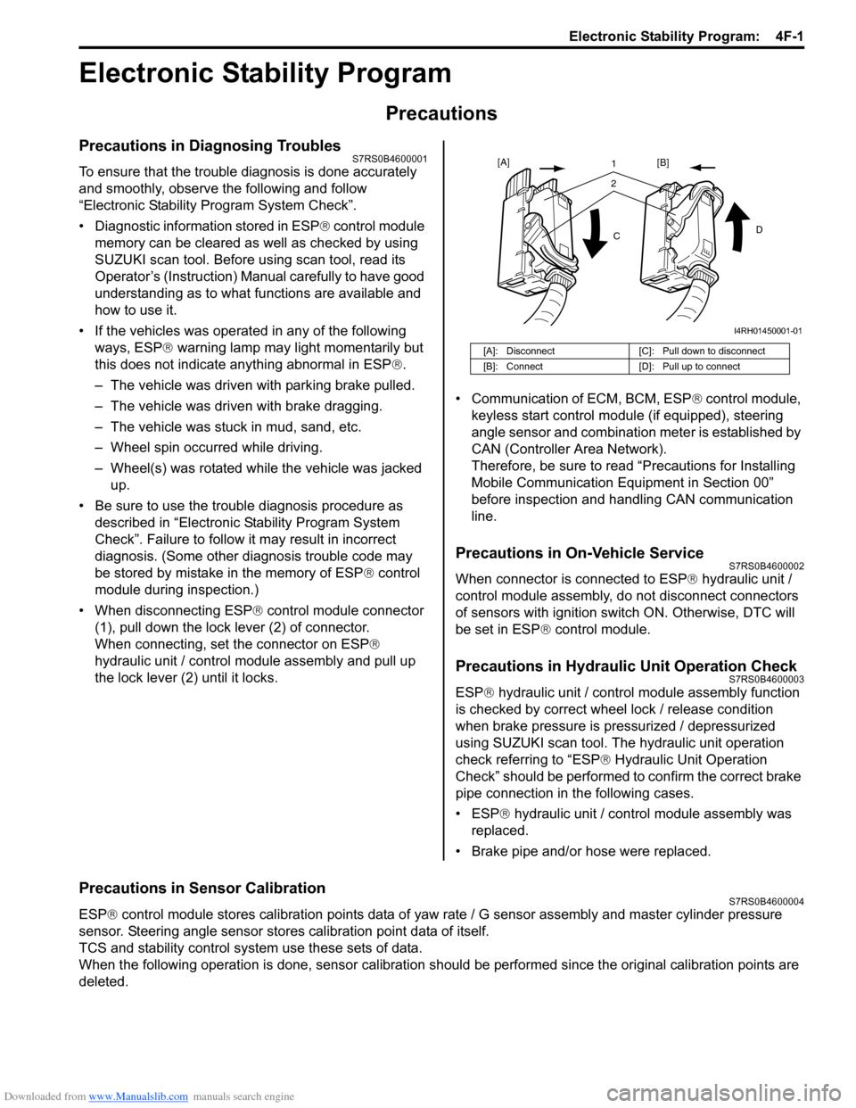
• When disconnecting ESP ® control module connector
(1), pull down the lock lever (2) of connector.
When connecting, set the connector on ESP ®
hydraulic unit / control module assembly and pull up
the lock lever (2) until it locks. • Communication of ECM, BCM, ESP
® control module,
keyless start control module (if equipped), steering
angle sensor and combination meter is established by
CAN (Controller Area Network).
Therefore, be sure to read “Precautions for Installing
Mobile Communication Equipment in Section 00”
before inspection and handling CAN communication
line.
Precautions in On-Vehicle ServiceS7RS0B4600002
When connector is connected to ESP ® hydraulic unit /
control module assembly, do not disconnect connectors
of sensors with ignition switch ON. Otherwise, DTC will
be set in ESP ® control module.
Precautions in Hydraulic Unit Operation CheckS7RS0B4600003
ESP® hydraulic unit / control module assembly function
is checked by correct wheel lock / release condition
when brake pressure is pressurized / depressurized
using SUZUKI scan tool. The hydraulic unit operation
check referring to “ESP ® Hydraulic Unit Operation
Check” should be performed to confirm the correct brake
pipe connection in the following cases.
• ESP® hydraulic unit / contro l module assembly was
replaced.
• Brake pipe and/or hose were replaced.
Precautions in Sensor CalibrationS7RS0B4600004
ESP ® control module stores calibration points data of yaw rate / G sensor assembly and master cylinder pressure
sensor. Steering angle sensor stores calibration point data of itself.
TCS and stability control system use these sets of data.
When the following operation is done, sensor calibration should be performed since the original calibration points are
deleted.
[A]: Disconnect [C]: Pull down to disconnect
[B]: Connect [D]: Pull up to connect
21
C D
[A]
[B]
I4RH01450001-01
Page 584 of 1496
Downloaded from www.Manualslib.com manuals search engine 4F-10 Electronic Stability Program:
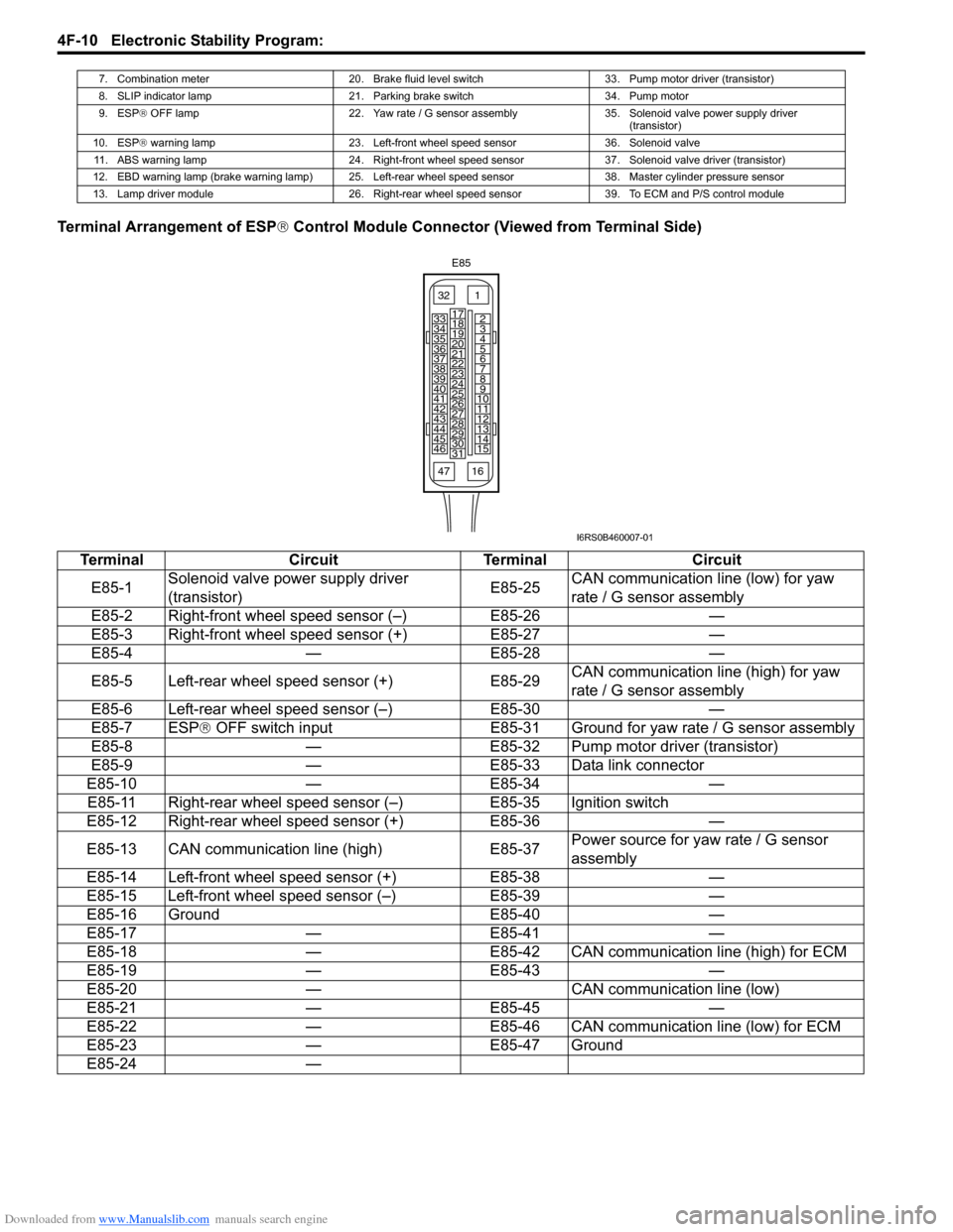
Terminal Arrangement of ESP® Control Module Connector (Viewed from Terminal Side)
7. Combination meter 20. Brake fluid level switch 33. Pump motor driver (transistor)
8. SLIP indicator lamp 21. Parking brake switch 34. Pump motor
9. ESP ® OFF lamp 22. Yaw rate / G sensor assembly 35. Solenoid valve power supply driver
(transistor)
10. ESP ® warning lamp 23. Left-front wheel speed sensor 36. Solenoid valve
11. ABS warning lamp 24. Right-front wheel speed sensor37. Solenoid valve driver (transistor)
12. EBD warning lamp (brake warning lamp) 25. Left-rear wheel speed sensor 38. Master cylinder pressure sensor
13. Lamp driver module 26. Right-rear wheel speed sensor 39. To ECM and P/S control module
Terminal CircuitTerminal Circuit
E85-1 Solenoid valve power supply driver
(transistor) E85-25CAN communication line (low) for yaw
rate / G sensor assembly
E85-2 Right-front wheel speed sensor (–) E85-26—
E85-3 Right-front wheel speed sensor (+) E85-27—
E85-4 —E85-28 —
E85-5 Left-rear wheel speed sensor (+) E85-29CAN communication line (high) for yaw
rate / G sensor assembly
E85-6 Left-rear wheel speed sensor (–) E85-30—
E85-7 ESP® OFF switch input E85-31 Ground for yaw rate / G sensor assembly
E85-8 —E85-32 Pump motor driver (transistor)
E85-9 —E85-33 Data link connector
E85-10 —E85-34 —
E85-11 Right-rear wheel speed sensor (–) E85-35 Ignition switch
E85-12 Right-rear wheel speed sensor (+) E85-36—
E85-13 CAN communication line (high) E85-37Power source for ya
w rate / G sensor
assembly
E85-14 Left-front wheel speed sensor (+) E85-38—
E85-15 Left-front wheel speed sensor (–) E85-39—
E85-16 Ground E85-40—
E85-17 —E85-41 —
E85-18 —E85-42 CAN communication line (high) for ECM
E85-19 —E85-43 —
E85-20 — CAN communication line (low)
E85-21 —E85-45 —
E85-22 —E85-46 CAN communication line (low) for ECM
E85-23 —E85-47 Ground
E85-24 —
E85
161
15
2
3
4
5
6
7
8
9
10
11
12
13
14
17
18
19
20
21
22
23
24
25
26
27
28
29
30
31
3233
34
35
36
37
38
39
40
41
42
43
44
45
46
47
I6RS0B460007-01
Page 585 of 1496
Downloaded from www.Manualslib.com manuals search engine Electronic Stability Program: 4F-11
Component Location
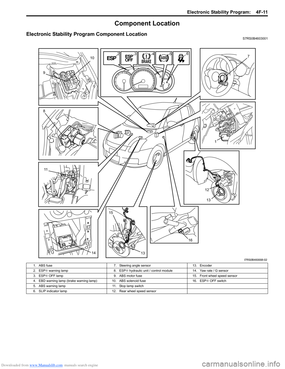
Electronic Stability Program Component LocationS7RS0B4603001
10
9
8
11
1415
13 1613
12 1 7
6
5
4
3
2
I7RS0B460008-02
1. ABS fuse 7. Steering angle sensor13. Encoder
2. ESP ® warning lamp 8. ESP® hydraulic unit / control module 14. Yaw rate / G sensor
3. ESP ® OFF lamp 9. ABS motor fuse 15. Front wheel speed sensor
4. EBD warning lamp (brake warning lamp) 10. ABS solenoid fuse 16. ESP® OFF switch
5. ABS warning lamp 11. Stop lamp switch
6. SLIP indicator lamp 12. Rear wheel speed sensor
Page 586 of 1496
Downloaded from www.Manualslib.com manuals search engine 4F-12 Electronic Stability Program:
Diagnostic Information and Procedures
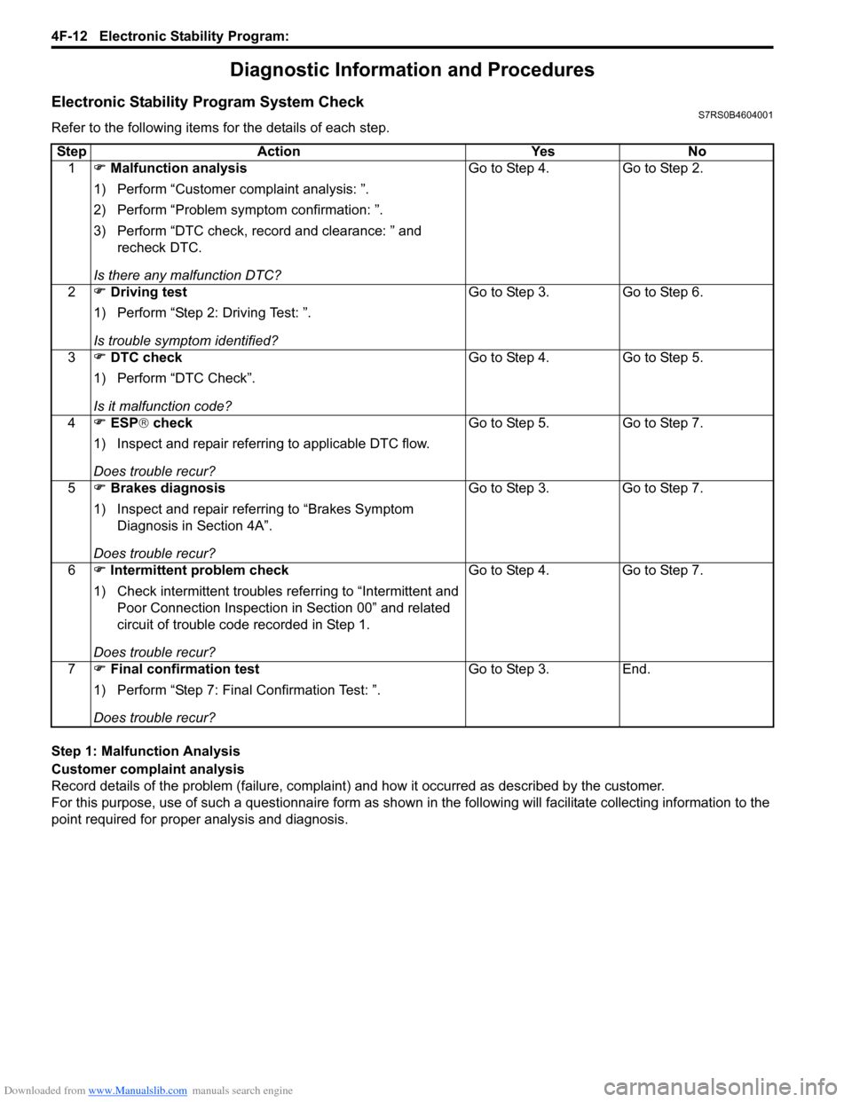
Electronic Stability Program System CheckS7RS0B4604001
Refer to the following items for the details of each step.
Step 1: Malfunction Analysis
Customer complaint analysis
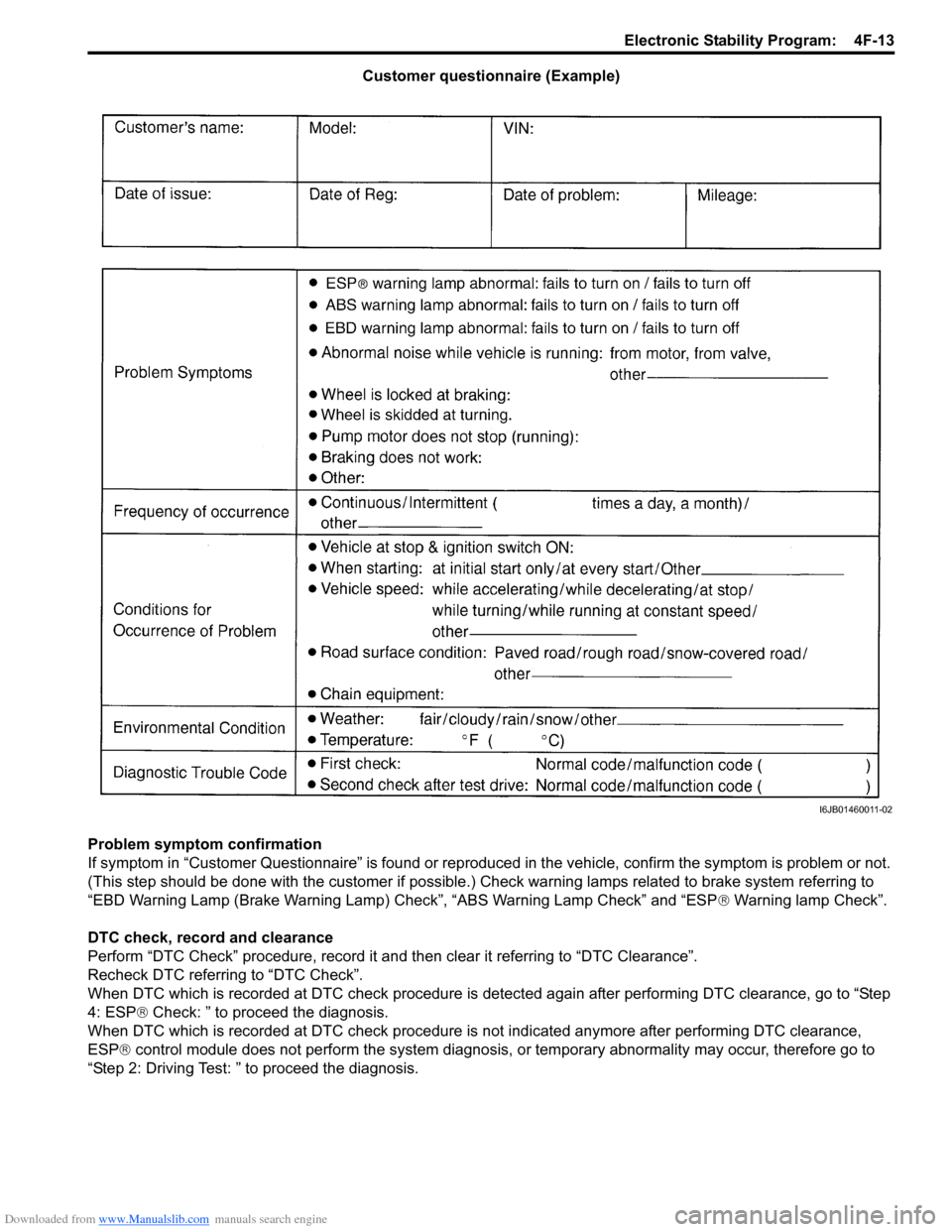
Record details of the problem (failure, complaint) and how it occurred as described by the customer.
For this purpose, use of such a questionnaire form as shown in the following will facilitate collec ting information to the
point required for proper analysis and diagnosis. Step Action Yes No
1 �) Malfunction analysis
1) Perform “Customer complaint analysis: ”.
2) Perform “Problem symptom confirmation: ”.
3) Perform “DTC check, record and clearance: ” and recheck DTC.
Is there any malfunction DTC? Go to Step 4. Go to Step 2.
2 �) Driving test
1) Perform “Step 2: Driving Test: ”.
Is trouble symptom identified? Go to Step 3. Go to Step 6.
3 �) DTC check
1) Perform “DTC Check”.
Is it malfunction code? Go to Step 4. Go to Step 5.
4 �) ESP ® check
1) Inspect and repair referring to applicable DTC flow.
Does trouble recur? Go to Step 5. Go to Step 7.
5 �) Brakes diagnosis
1) Inspect and repair referring to “Brakes Symptom Diagnosis in Section 4A”.
Does trouble recur? Go to Step 3. Go to Step 7.
6 �) Intermittent problem check
1) Check intermittent troubles referring to “Intermittent and
Poor Connection Inspection in Section 00” and related
circuit of trouble code recorded in Step 1.
Does trouble recur? Go to Step 4. Go to Step 7.
7 �) Final confirmation test
1) Perform “Step 7: Final Confirmation Test: ”.
Does trouble recur? Go to Step 3. End.
Page 587 of 1496
Downloaded from www.Manualslib.com manuals search engine Electronic Stability Program: 4F-13
Customer questionnaire (Example)
Problem symptom confirmation
If symptom in “Customer Questionnaire” is found or reproduced in the vehicle, confirm the symptom is problem or not.
(This step should be done with the customer if possible.) Check warning lamps related to brake system referring to
“EBD Warning Lamp (Brake Warning Lamp) Check”, “ABS Warning Lamp Check” and “ESP ® Warning lamp Check”.
DTC check, record and clearance
Perform “DTC Check” procedure, record it and then clear it referring to “DTC Clearance”.
Recheck DTC referring to “DTC Check”.
When DTC which is recorded at DTC check procedure is detected again after performing DTC clearance, go to “Step
4: ESP ® Check: ” to proceed the diagnosis.
When DTC which is recorded at DTC check procedure is not indicated anymore after performing DTC clearance,
ESP ® control module does not perform the system diagnosis, or temporary abnormality may occur, therefore go to
“Step 2: Driving Test: ” to proceed the diagnosis.
I6JB01460011-02
Page 588 of 1496
Downloaded from www.Manualslib.com manuals search engine 4F-14 Electronic Stability Program:
Step 2: Driving Test
Test the vehicle at 40 km/h for more than a minute including left and right turns and check if any trouble symptom
(such as ESP ® warning lamp and/or ABS warning lamp) exists.
If the malfunction DTC is confirmed at ignition switch ON, proceed to Step 3.
If the malfunction DTC is not confirmed at ignition switch ON, proceed to Step 6.
Step 3: DTC Check
Recheck DTC referring to “DTC Check”.
Step 4: ESP ® Check
According to ESP ® Check for the DTC confirmation in Step 3, locate the cause of the trouble, namely in a sensor,
switch, wire harness, connector, actuator assembly or other part and repair or replace faulty parts.
Step 5: Brakes Diagnosis
Check the parts or system suspected as a possible cause referring to “Brakes Symptom Diagnosis in Section 4A” and
based on symptoms appearing on the vehicle (symptom obtain ed through Steps 1 and 2 and repair or replace faulty
parts, if any).
Step 6: Intermittent Problem Check
Check parts where an intermittent trouble is easy to occur (e.g., wire harness, connector, etc.), referring to
“Intermittent and Poor Connection Inspection in Section 00” and related circuit of trouble code recorded in Step 1 to 3.
Step 7: Final Confirmation Test
Confirm that the problem symptom has gone and the ESP ® is free from any abnormal conditions. If what has been
repaired is related to the malfunction DTC, clear the DTC once referrin g to “DTC Clearance” and perform test driving
and confirm that no DTC is indicated.
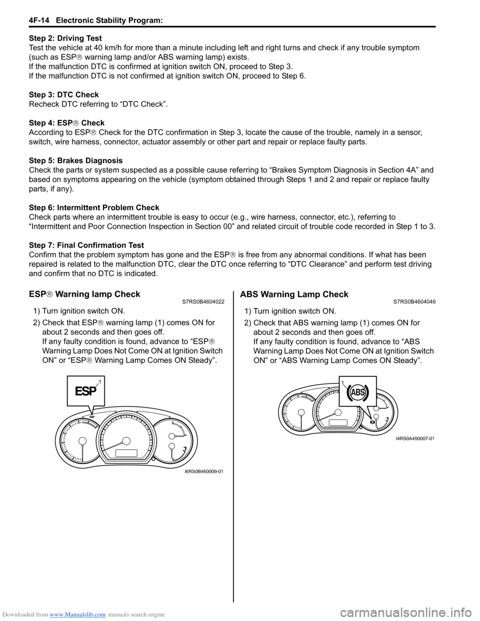
ESP ® Warning lamp CheckS7RS0B4604022
1) Turn ignition switch ON.
2) Check that ESP ® warning lamp (1) comes ON for
about 2 seconds and then goes off.
If any faulty condition is found, advance to “ESP ®
Warning Lamp Does Not Come ON at Ignition Switch
ON” or “ESP ® Warning Lamp Comes ON Steady”.
ABS Warning Lamp CheckS7RS0B4604046
1) Turn ignition switch ON.
2) Check that ABS warning lamp (1) comes ON for
about 2 seconds and then goes off.
If any faulty condition is found, advance to “ABS
Warning Lamp Does Not Come ON at Ignition Switch
ON” or “ABS Warning Lamp Comes ON Steady”.
1
I6RS0B460009-01
11
I4RS0A450007-01
Page 589 of 1496
Downloaded from www.Manualslib.com manuals search engine Electronic Stability Program: 4F-15
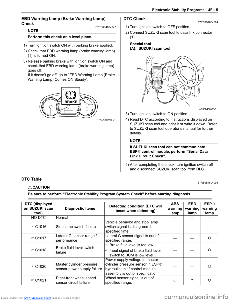
EBD Warning Lamp (Brake Warning Lamp)
Check
S7RS0B4604047
NOTE
Perform this check on a level place.
1) Turn ignition switch ON with parking brake applied.
2) Check that EBD warning lamp (brake warning lamp)
(1) is turned ON.
3) Release parking brake with ignition switch ON and check that EBD warning lamp (brake warning lamp)
goes off.
If it doesn't go off, go to “EBD Warning Lamp (Brake
Warning Lamp) Comes ON Steady”.
DTC CheckS7RS0B4604004
1) Turn ignition switch to OFF position.
2) Connect SUZUKI scan tool to data link connector (1).
Special tool
(A): SUZUKI scan tool
3) Turn ignition switch to ON position.
4) Read DTC according to instructions displayed on
SUZUKI scan tool and print it or write it down. Refer
to SUZUKI scan tool operator’s manual for further
details.
NOTE
If SUZUKI scan tool can not communicate
ESP® control module, perform “Serial Data
Link Circuit Check”.
5) After completing the check, turn ignition switch off and disconnect SUZUKI scan tool from DLC.
DTC TableS7RS0B4604005
CAUTION!
Be sure to perform “Electronic Stability Program System Check” before starting diagnosis.
BRAKE
1
I4RS0A450008-01
(A)
1
I4RS0B450003-01
DTC (displayed
on SUZUKI scan tool) Diagnostic Items
Detecting condition (DTC will
beset when detecting) ABS
warning lamp EBD
warning lamp ESP
®
warning lamp
NO DTC Normal — — — —
�) C1016 Stop lamp switch failure Vehicle behavior and stop lamp
switch signal is disagreed for
specified time.———
�) C1017 Lateral G sensor range /
performance Lateral G sensor signal is out of
specified range.
——
�{
�) C1018 Brake fluid level switch
failure • Brake fluid level is too low.
• Input signal of brake fluid level
switch to BCM is low level. ——
�{
�) C1020 Master cylinder pressure
sensor power supply failure Power supply volt
age to master
cylinder pressure sensor in ESP ®
hydraulic unit / control module
assembly is out of specification. ——
�{
�) C1021 Right-front wheel speed
sensor circuit failure Wheel sensor signal is out of
specified range.
�{
*1 �{