Psi SUZUKI SWIFT 2006 2.G Service Workshop Manual
[x] Cancel search | Manufacturer: SUZUKI, Model Year: 2006, Model line: SWIFT, Model: SUZUKI SWIFT 2006 2.GPages: 1496, PDF Size: 34.44 MB
Page 108 of 1496
Downloaded from www.Manualslib.com manuals search engine 1A-58 Engine General Information and Diagnosis:
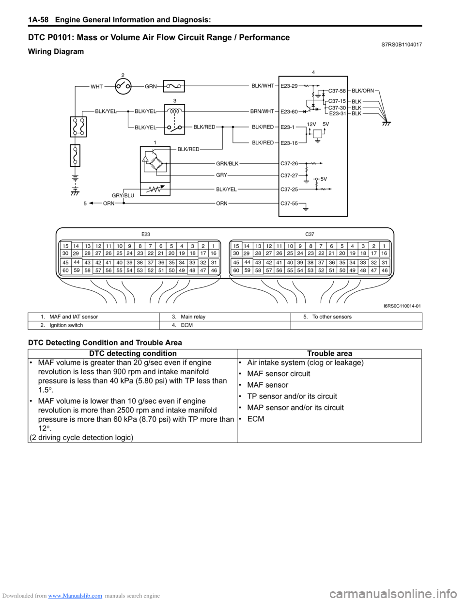
DTC P0101: Mass or Volume Air Flow Circuit Range / PerformanceS7RS0B1104017
Wiring Diagram
DTC Detecting Condition and Trouble Area
E23C37
34
1819
567
1011
17
20
47 46
495051
2122
52 16
25 9
24
14
29
55
57 54 53
59
60 58 2
262728
15
30
56 4832 31
34353637
40
42 39 38
44
45 43 41 331
1213
238
34
1819
567
1011
17
20
47 46
495051
2122
52 16
25 9
24
14
29
55
57 54 53
59
60 58 2
262728
15
30
56 4832 31
34353637
40
42 39 38
44
45 43 41 331
1213
238
BLK/WHT
BLK/RED
BLK/RED
WHT
BLK/YELBLK/YEL
BLK/YEL
GRN
BRN/WHT
12V 5V
5V
2 3 4
E23-29
E23-60
E23-1
E23-16
BLK/ORN
BLKBLK
BLK/RED
BLK/YELGRY/BLU
ORN
1BLK/RED
5
E23-31BLK
ORN
GRY
GRN/BLK
C37-58
C37-15
C37-30
C37-26
C37-27
C37-25
C37-55
I6RS0C110014-01
1. MAF and IAT sensor
3. Main relay5. To other sensors
2. Ignition switch 4. ECM
DTC detecting condition Trouble area
• MAF volume is greater than 20 g/sec even if engine revolution is less than 900 rpm and intake manifold
pressure is less than 40 kPa (5.80 psi) with TP less than
1.5 °.
• MAF volume is lower than 10 g/sec even if engine
revolution is more than 2500 rpm and intake manifold
pressure is more than 60 kPa (8.70 psi) with TP more than
12 °.
(2 driving cycle detection logic) • Air intake system (clog or leakage)
• MAF sensor circuit
•MAF sensor
• TP sensor and/or its circuit
• MAP sensor and/or its circuit
•ECM
Page 114 of 1496
Downloaded from www.Manualslib.com manuals search engine 1A-64 Engine General Information and Diagnosis:
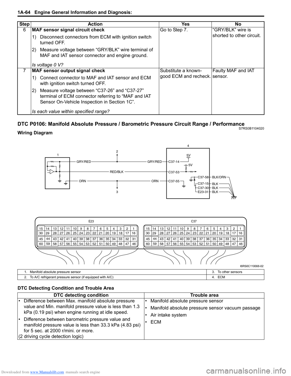
DTC P0106: Manifold Absolute Pressure / Barometric Pressure Circuit Range / PerformanceS7RS0B1104020
Wiring Diagram
DTC Detecting Condition and Trouble Area6
MAF sensor signal circuit check
1) Disconnect connectors from ECM with ignition switch
turned OFF.
2) Measure voltage between “GRY/BLK” wire terminal of MAF and IAT sensor connector and engine ground.
Is voltage 0 V? Go to Step 7. “GRY/BLK” wire is
shorted to other circuit.
7 MAF sensor output signal check
1) Connect connector to MAF and IAT sensor and ECM
with ignition swit ch turned OFF.
2) Measure voltage between “C37-26” and “C37-27” terminal of ECM connector referring to “MAF and IAT
Sensor On-Vehicle Inspection in Section 1C”.
Is each value within specified range? Substitute a known-
good ECM and recheck.
Faulty MAF and IAT
sensor.
Step Action Yes No
E23
C37
34
1819
567
1011
17
20
47 46
495051
2122
52 16
25 9
24
14
29
55
57 54 53
59
60 58 2
262728
15
30
56 4832 31
34353637
40
42 39 38
44
45 43 41 331
1213
238
34
1819
567
1011
17
20
47 46
495051
2122
52 16
25 9
24
14
29
55
57 54 53
59
60 58 2
262728
15
30
56 4832 31
34353637
40
42 39 38
44
45 43 41 331
1213
238
4
C37-58
C37-15 C37-30
BLK/ORN
BLKBLKE23-31 BLK
1
2
3
GRY/REDGRY/RED
5V
5VC37-14
C37-53
C37-55
RED/BLK
ORNORN
I6RS0C110008-02
1. Manifold absolute pressure sensor
3. To other sensors
2. To A/C refrigerant pressure sensor (if equipped with A/C) 4. ECM
DTC detecting condition Trouble area
• Difference between Max. manifold absolute pressure value and Min. manifold pressure value is less than 1.3
kPa (0.19 psi) when engine running at idle speed.
• Difference between barometric pressure value and manifold pressure value is less than 33.3 kPa (4.83 psi)
for 5 sec. at 2000 r/mini. or more.
(2 driving cycle detection logic) • Manifold absolute pressure sensor
• Manifold absolute pressure sensor vacuum passage
• Air intake system
•ECM
Page 233 of 1496
Downloaded from www.Manualslib.com manuals search engine Engine General Information and Diagnosis: 1A-183
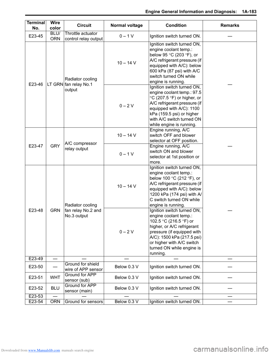
E23-45BLU/
ORNThrottle actuator
control relay output
0 – 1 V Ignition switch turned ON. —
E23-46 LT GRN Radiator cooling
fan relay No.1
output 10 – 14 V
Ignition switch turned ON,
engine coolant temp.:
below 95
°C (203 ° F), or
A/C refrigerant pressure (if
equipped with A/C): below
600 kPa (87 psi) with A/C
switch turned ON while
engine is running. —
0 – 2 V Ignition switch turned ON,
engine coolant temp.: 97.5
°
C (207.5 ° F) or higher, or
A/C refrigerant pressure (if
equipped with A/C): 1100
kPa (159.5 psi) or higher
with A/C switch turned ON
while engine is running.
E23-47 GRY A/C compressor
relay output 10 – 14 V
Engine running, A/C
switch OFF and blower
selector at OFF position.
—
0 – 1 V Engine running, A/C
switch ON and blower
selector at 1st position or
more.
E23-48 GRN Radiator cooling
fan relay No.2 and
No.3 output 10 – 14 V
Ignition switch turned ON,
engine coolant temp.:
below 100
°C (212 °F), or
A/C refrigerant pressure (if
equipped with A/C): below
1200 kPa (174 psi) with A/
C switch turned ON while
engine is running. —
0 – 2 V Ignition switch turned ON,
engine coolant temp.:
102.5
°C (216.5 °F) or
higher, or A/C refrigerant
pressure (if equipped with
A/C): 1500 kPa (217.5 psi)
or higher with A/C switch
turned ON while engine is
running.
E23-49 — — — — —
E23-50 — Ground for shield
wire of APP sensor Below 0.3 V Ignition switch turned ON. —
E23-51 WHT Ground for APP
sensor (sub) Below 0.3 V Ignition switch turned ON. —
E23-52 BLU Ground for APP
sensor (main) Below 0.3 V Ignition switch turned ON. —
E23-53 — — — — —
E23-54 ORN Ground for sensors Below 0.3 V Ignition switch turned ON. —
Terminal
No. Wire
color Circuit Normal voltage Condition Remarks
Page 234 of 1496
Downloaded from www.Manualslib.com manuals search engine 1A-184 Engine General Information and Diagnosis:
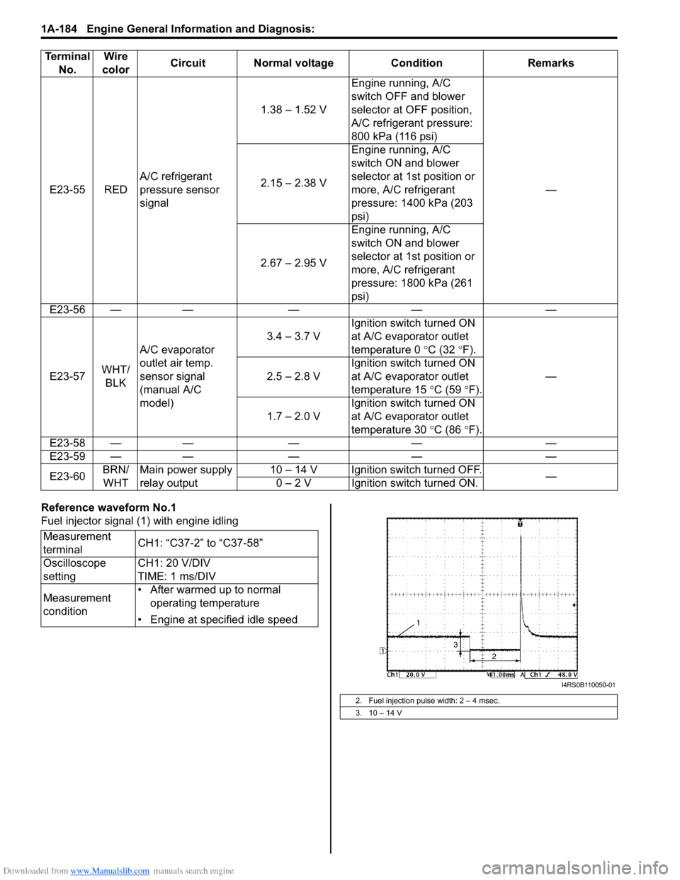
Reference waveform No.1
Fuel injector signal (1) with engine idling
E23-55 RED
A/C refrigerant
pressure sensor
signal 1.38 – 1.52 V
Engine running, A/C
switch OFF and blower
selector at OFF position,
A/C refrigerant pressure:
800 kPa (116 psi)
—
2.15 – 2.38 V Engine running, A/C
switch ON and blower
selector at 1st position or
more, A/C refrigerant
pressure: 1400 kPa (203
psi)
2.67 – 2.95 V Engine running, A/C
switch ON and blower
selector at 1st position or
more, A/C refrigerant
pressure: 1800 kPa (261
psi)
E23-56 — — — — —
E23-57 WHT/
BLK A/C evaporator
outlet air temp.
sensor signal
(manual A/C
model) 3.4 – 3.7 V
Ignition switch turned ON
at A/C evaporator outlet
temperature 0
°C (32 °F).
—
2.5 – 2.8 V Ignition switch turned ON
at A/C evaporator outlet
temperature 15
°C (59 °F).
1.7 – 2.0 V Ignition switch turned ON
at A/C evaporator outlet
temperature 30
°C (86 °F).
E23-58 — — — — —
E23-59 — — — — —
E23-60 BRN/
WHT Main power supply
relay output 10 – 14 V Ignition switch turned OFF.
—
0 – 2 V Ignition switch turned ON.
Terminal
No. Wire
color Circuit Normal voltage Condition Remarks
Measurement
terminal CH1: “C37-2” to “C37-58”
Oscilloscope
setting CH1: 20 V/DIV
TIME: 1 ms/DIV
Measurement
condition • After warmed up to normal
operating temperature
• Engine at specified idle speed
2. Fuel injection pulse width: 2 – 4 msec.
3. 10 – 14 V
I4RS0B110050-01
Page 269 of 1496
Downloaded from www.Manualslib.com manuals search engine Aux. Emission Control Devices: 1B-2
EVAP Canister Purge Valve and Its Circuit
Inspection
S7RS0B1206002
WARNING!
Do not apply vacuum by mouth; otherwise
harmful fuel vapor can be breathed in.
CAUTION!
Do not apply vacuum more than –86 kPa (–
12.47 psi); otherwise EVAP canister purge
valve could be damaged.
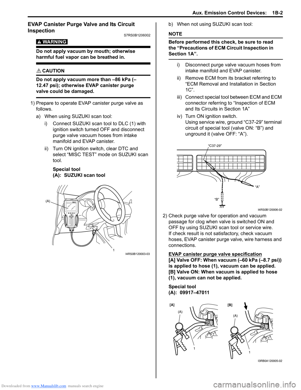
1) Prepare to operate EVAP canister purge valve as follows.
a) When using SUZUKI scan tool:
i) Connect SUZUKI scan tool to DLC (1) with ignition switch turned OFF and disconnect
purge valve vacuum hoses from intake
manifold and EVAP canister.
ii) Turn ON ignition switch, clear DTC and select “MISC TEST” mode on SUZUKI scan
tool.
Special tool
(A): SUZUKI scan tool b) When not using SUZUKI scan tool:
NOTE
Before performed this check, be sure to read
the “Precautions of ECM Circuit Inspection in
Section 1A”.
i) Disconnect purge valve vacuum hoses from
intake manifold and EVAP canister.
ii) Remove ECM from it s bracket referring to
“ECM Removal and Inst allation in Section
1C”.
iii) Connect special tool between ECM and ECM connector referring to “Inspection of ECM
and Its Circuits in Section 1A”
iv) Turn ON ignition switch. Using service wire, ground “C37-29” terminal
circuit of special tool (valve ON: “B”) and
unground it (valve OFF: “A”).
2) Check purge valve for operation and vacuum passage for clog when valve is switched ON and
OFF by using SUZUKI scan tool or service wire.
If check result is not satisfactory, check vacuum
hoses, EVAP canister purge valve, wire harness and
connections.
EVAP canister purge valve specification
[A] Valve OFF: When vacuum (–60 kPa (–8.7 psi))
is applied to hose (1), vacuum can be applied.
[B] Valve ON: When vacuum is applied to hose
(1), vacuum can not be applied.
Special tool
(A): 09917–47011
(A)
1
I4RS0B120003-03
“C37-29”“A”
“B”
I4RS0B120006-02
[A] [B]
1
(A)1
(A)
I3RB0A120005-02
Page 270 of 1496
Downloaded from www.Manualslib.com manuals search engine 1B-3 Aux. Emission Control Devices:
Vacuum Passage InspectionS7RS0B1206003
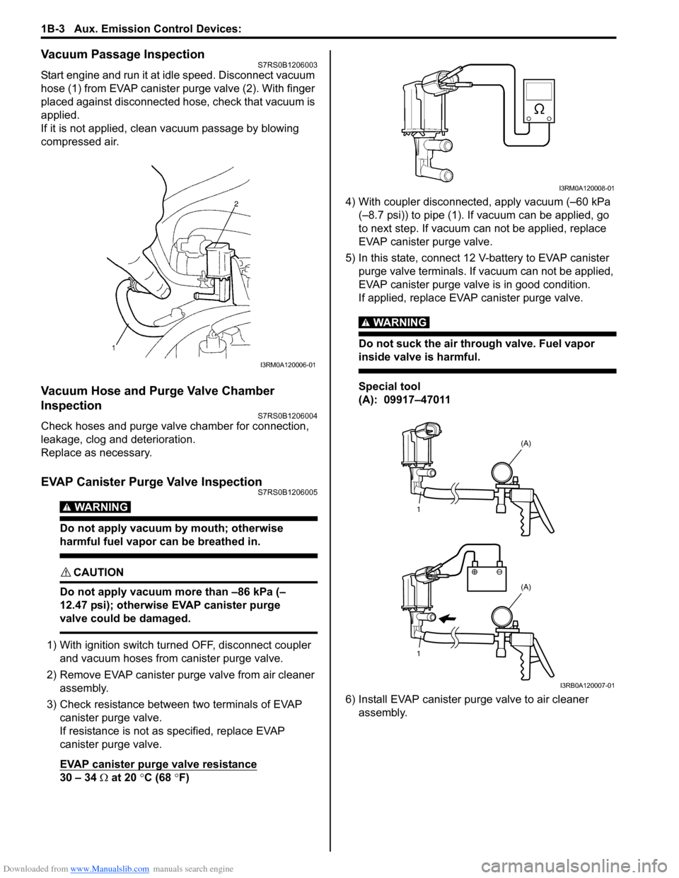
Start engine and run it at idle speed. Disconnect vacuum
hose (1) from EVAP canister purge valve (2). With finger
placed against disconnected hose, check that vacuum is
applied.
If it is not applied, clean vacuum passage by blowing
compressed air.
Vacuum Hose and Purge Valve Chamber
Inspection
S7RS0B1206004
Check hoses and purge valv e chamber for connection,
leakage, clog and deterioration.
Replace as necessary.
EVAP Canister Purge Valve InspectionS7RS0B1206005
WARNING!
Do not apply vacuum by mouth; otherwise
harmful fuel vapor can be breathed in.
CAUTION!
Do not apply vacuum more than –86 kPa (–
12.47 psi); otherwise EVAP canister purge
valve could be damaged.
1) With ignition switch turned OFF, disconnect coupler and vacuum hoses from canister purge valve.
2) Remove EVAP canister purge valve from air cleaner assembly.
3) Check resistance between two terminals of EVAP canister purge valve.
If resistance is not as specified, replace EVAP
canister purge valve.
EVAP canister purge valve resistance
30 – 34 Ω at 20 °C (68 °F) 4) With coupler disconnected, apply vacuum (–60 kPa
(–8.7 psi)) to pipe (1). If vacuum can be applied, go
to next step. If vacuum can not be applied, replace
EVAP canister purge valve.
5) In this state, connect 12 V-battery to EVAP canister purge valve terminals. If vacuum can not be applied,
EVAP canister purge valve is in good condition.
If applied, replace EVAP canister purge valve.
WARNING!
Do not suck the air through valve. Fuel vapor
inside valve is harmful.
Special tool
(A): 09917–47011
6) Install EVAP canister purge valve to air cleaner assembly.
I3RM0A120006-01
I3RM0A120008-01
1
1 (A)
(A)
I3RB0A120007-01
Page 290 of 1496
Downloaded from www.Manualslib.com manuals search engine 1D-5 Engine Mechanical:
11) Connect negative cable at battery.
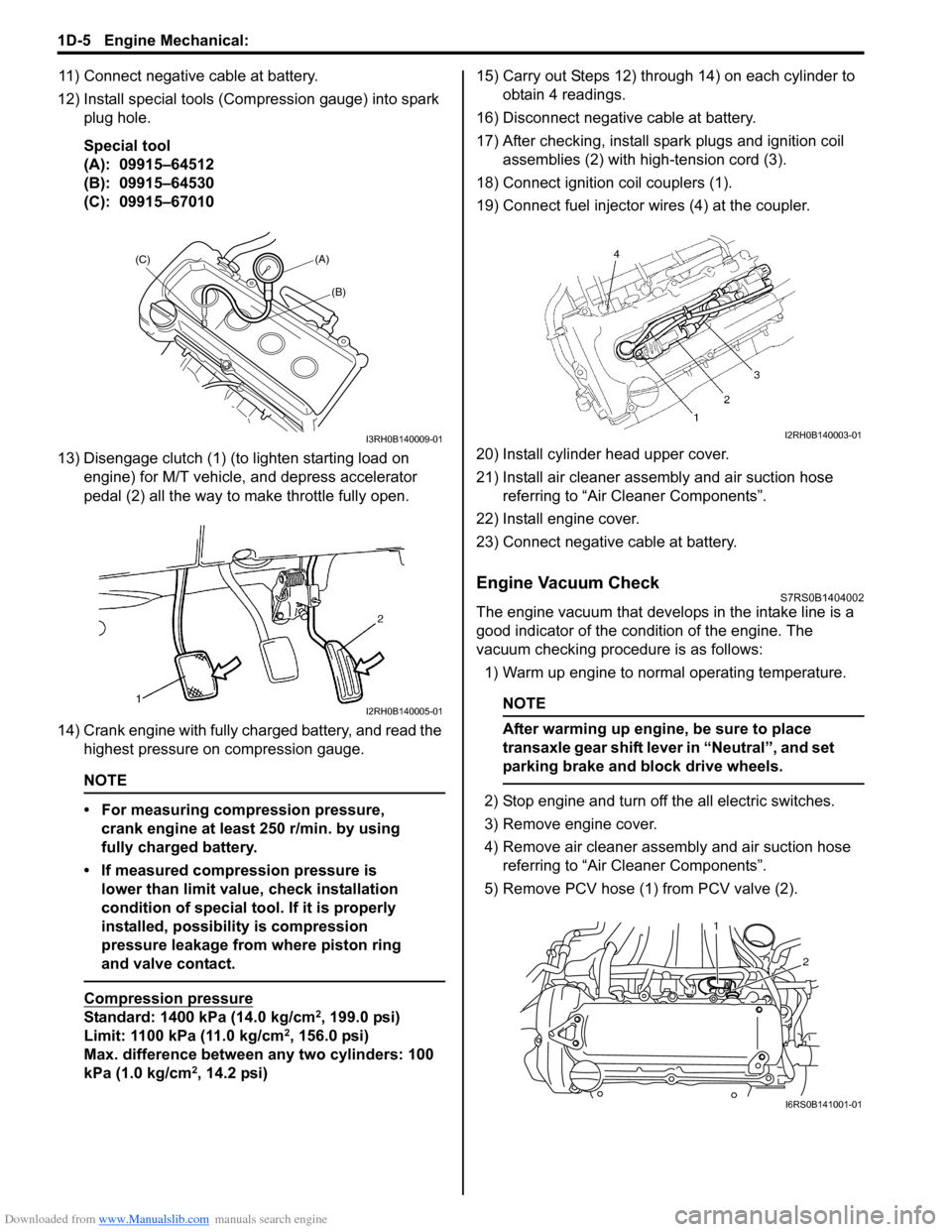
12) Install special tools (Compression gauge) into spark plug hole.
Special tool
(A): 09915–64512
(B): 09915–64530
(C): 09915–67010
13) Disengage clutch (1) (to lighten starting load on engine) for M/T vehicle, and depress accelerator
pedal (2) all the way to make throttle fully open.
14) Crank engine with fully charged battery, and read the highest pressure on compression gauge.
NOTE
• For measuring compression pressure, crank engine at least 250 r/min. by using
fully charged battery.
• If measured compression pressure is lower than limit value, check installation
condition of special tool. If it is properly
installed, possibility is compression
pressure leakage from where piston ring
and valve contact.
Compression pressure
Standard: 1400 kPa (14.0 kg/cm2, 199.0 psi)
Limit: 1100 kPa (11.0 kg/cm2, 156.0 psi)
Max. difference between any two cylinders: 100
kPa (1.0 kg/cm
2, 14.2 psi) 15) Carry out Steps 12) through 14) on each cylinder to
obtain 4 readings.
16) Disconnect negative cable at battery.
17) After checking, install spark plugs and ignition coil assemblies (2) with high-tension cord (3).
18) Connect ignition coil couplers (1).
19) Connect fuel injector wires (4) at the coupler.
20) Install cylinder head upper cover.
21) Install air cleaner assembly and air suction hose referring to “Air Cleaner Components”.
22) Install engine cover.
23) Connect negative cable at battery.
Engine Vacuum CheckS7RS0B1404002
The engine vacuum that develops in the intake line is a
good indicator of the condition of the engine. The
vacuum checking procedure is as follows:
1) Warm up engine to normal operating temperature.
NOTE
After warming up engine, be sure to place
transaxle gear shift lever in “Neutral”, and set
parking brake and block drive wheels.
2) Stop engine and turn off the all electric switches.
3) Remove engine cover.
4) Remove air cleaner assembly and air suction hose referring to “Air Cleaner Components”.
5) Remove PCV hose (1) from PCV valve (2).
(A)
(C)
(B)
I3RH0B140009-01
I2RH0B140005-01
I2RH0B140003-01
2
1
I6RS0B141001-01
Page 310 of 1496
Downloaded from www.Manualslib.com manuals search engine 1D-25 Engine Mechanical:
Timing Chain and Chain Tensioner Removal
and Installation
S7RS0B1406018
Removal
CAUTION!
After timing chain is removed, never turn
crankshaft and camshafts independently
more than its allowable turning range
described in “Installation”.
If turned, interferen ce may occur between
piston and valves and valves themselves,
and parts related to piston and valves may be
damaged.
1) Remove timing chain cover referring to “Timing Chain Cover Removal and Installation”.
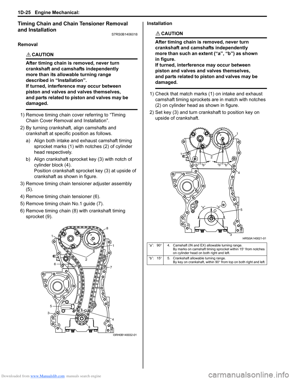
2) By turning crankshaft, align camshafts and crankshaft at specific position as follows.
a) Align both intake and exhaust camshaft timing sprocket marks (1) with notches (2) of cylinder
head respectively.
b) Align crankshaft sprocket key (3) with notch of cylinder block (4).
Position crankshaft sprocke t key (3) at upside of
crankshaft as shown in figure.
3) Remove timing chain tensioner adjuster assembly (5).
4) Remove timing chain tensioner (6).
5) Remove timing chain No.1 guide (7).
6) Remove timing chain (8) with crankshaft timing sprocket (9). Installation
CAUTION!
After timing chain is removed, never turn
crankshaft and camshafts independently
more than such an extent (“a”, “b”) as shown
in figure.
If turned, interferen
ce may occur between
piston and valves and valves themselves,
and parts related to piston and valves may be
damaged.
1) Check that match marks (1) on intake and exhaust camshaft timing sprockets are in match with notches
(2) on cylinder head as shown in figure.
2) Set key (3) and turn crankshaft to position key on upside of crankshaft.
3
4
1
1
2
5
67
8
9
I3RH0B140032-01
“a”: 90 °4. Camshaft (IN and EX) allowable turning range.
By marks on camshaft timing sprocket within 15 ° from notches
on cylinder head on both right and left.
“b”: 15 °5. Crankshaft allowable turning range.
By key on crankshaft, within 90 ° from top on both right and left.
“a”
“b”
“b”“b”
“b”
“a”
1
12
4
3
5
I4RS0A140021-01
Page 312 of 1496
Downloaded from www.Manualslib.com manuals search engine 1D-27 Engine Mechanical:
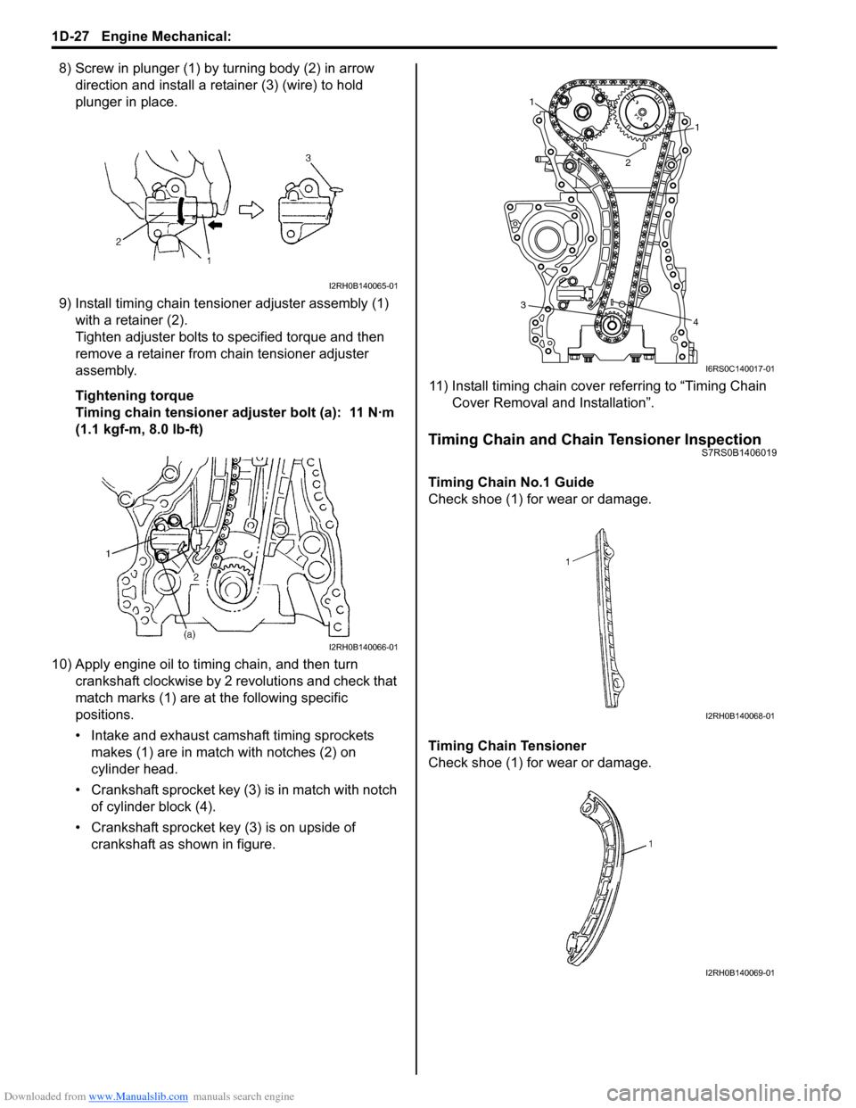
8) Screw in plunger (1) by turning body (2) in arrow direction and install a reta iner (3) (wire) to hold
plunger in place.
9) Install timing chain tensioner adjuster assembly (1) with a retainer (2).
Tighten adjuster bolts to specified torque and then
remove a retainer from chain tensioner adjuster
assembly.
Tightening torque
Timing chain tensioner adjuster bolt (a): 11 N·m
(1.1 kgf-m, 8.0 lb-ft)
10) Apply engine oil to timing chain, and then turn crankshaft clockwise by 2 revolutions and check that
match marks (1) are at the following specific
positions.
• Intake and exhaust camshaft timing sprockets makes (1) are in match with notches (2) on
cylinder head.
• Crankshaft sprocket key (3) is in match with notch of cylinder block (4).
• Crankshaft sprocket key (3) is on upside of crankshaft as shown in figure. 11) Install timing chain cover referring to “Timing Chain
Cover Removal and Installation”.
Timing Chain and Chain Tensioner InspectionS7RS0B1406019
Timing Chain No.1 Guide
Check shoe (1) for wear or damage.
Timing Chain Tensioner
Check shoe (1) for wear or damage.
I2RH0B140065-01
I2RH0B140066-01
1
1
2
3 4
I6RS0C140017-01
I2RH0B140068-01
I2RH0B140069-01
Page 353 of 1496
Downloaded from www.Manualslib.com manuals search engine Engine Lubrication System: 1E-1
Engine
Engine Lubrication System
General Description
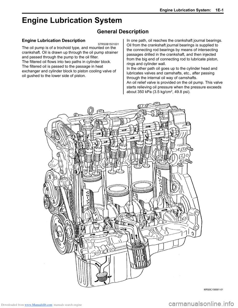
Engine Lubrication DescriptionS7RS0B1501001
The oil pump is of a trochoid type, and mounted on the
crankshaft. Oil is drawn up through the oil pump strainer
and passed through the pump to the oil filter.
The filtered oil flows into two paths in cylinder block.
The filtered oil is passed to the passage in heat
exchanger and cylinder block to piston cooling valve of
oil gushed to the lower side of piston. In one path, oil reaches the crankshaft journal bearings.
Oil from the crankshaft journal bearings is supplied to
the connecting rod bearings by means of intersecting
passages drilled in the cran
kshaft, and then injected
from the big end of connecting rod to lubricate piston,
rings and cylinder wall.
In the other path oil goes up to the cylinder head and
lubricates valves and camshafts, etc., after passing
through the internal oil way of camshafts.
An oil relief valve is provided on the oil pump. This valve
starts relieving oil pressure when the pressure exceeds
about 350 kPa (3.5 kg/cm
2, 49.8 psi).
I6RS0C150001-01