driver side SUZUKI SWIFT 2006 2.G Service Workshop Manual
[x] Cancel search | Manufacturer: SUZUKI, Model Year: 2006, Model line: SWIFT, Model: SUZUKI SWIFT 2006 2.GPages: 1496, PDF Size: 34.44 MB
Page 6 of 1496
Downloaded from www.Manualslib.com manuals search engine 00-1 Precautions:
Precautions
Precautions
Precautions
Precautions for Vehicles Equipped with a
Supplemental Restraint (Air Bag) System
S7RS0B0000001
WARNING!
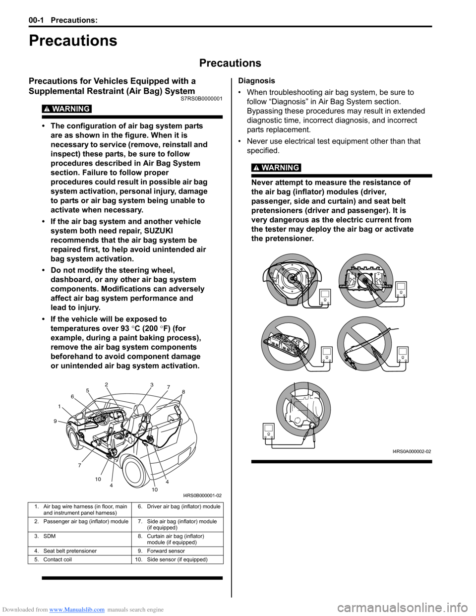
• The configuration of air bag system parts are as shown in the figure. When it is
necessary to service (remove, reinstall and
inspect) these parts, be sure to follow
procedures described in Air Bag System
section. Failure to follow proper
procedures could result in possible air bag
system activation, personal injury, damage
to parts or air bag system being unable to
activate when necessary.
• If the air bag system and another vehicle system both need repair, SUZUKI
recommends that the air bag system be
repaired first, to help avoid unintended air
bag system activation.
• Do not modify the steering wheel, dashboard, or any other air bag system
components. Modifications can adversely
affect air bag system performance and
lead to injury.
• If the vehicle will be exposed to temperatures over 93 °C (200 °F) (for
example, during a paint baking process),
remove the air bag system components
beforehand to avoid component damage
or unintended air bag system activation.
Diagnosis
• When troubleshooting air bag system, be sure to follow “Diagnosis” in Air Bag System section.
Bypassing these procedures may result in extended
diagnostic time, incorrect diagnosis, and incorrect
parts replacement.
• Never use electrical test equipment other than that specified.
WARNING!
Never attempt to measure the resistance of
the air bag (inflator) modules (driver,
passenger, side and curtain) and seat belt
pretensioners (driver and passenger). It is
very dangerous as the electric current from
the tester may deploy the air bag or activate
the pretensioner.
1. Air bag wire harness (in floor, main and instrument panel harness) 6. Driver air bag (inflator) module
2. Passenger air bag (inflator) module 7. Side air bag (inflator) module (if equipped)
3. SDM 8. Curtain air bag (inflator) module (if equipped)
4. Seat belt pretensioner 9. Forward sensor
5. Contact coil 10. Side sensor (if equipped)
1 2
3
4
4
5
6
7 7
8
9
10 10
I4RS0B000001-02
I4RS0A000002-02
Page 7 of 1496
Downloaded from www.Manualslib.com manuals search engine Precautions: 00-2
Servicing and Handling
WARNING!
Many of service procedures require
disconnection of “A/BAG” fuse and all air
bag (inflator) module(s) from initiator circuit
to avoid an accidental deployment.
Driver, Passenger, Side and Curtain Air Bag
(Inflator) Modules
• For handling and storage of a live air bag (inflator) module, select a place where the
ambient temperature below 65 °C (150 ° F),
without high humidity and away from
electric noise.
• When carrying a live air bag (inflator) module, make sure the bag opening is
pointed away from you. In case of an
accidental deployment, the bag will then
deploy with minimal chance of injury.
Never carry the air bag (inflator) module by
the wires or connector on the underside of
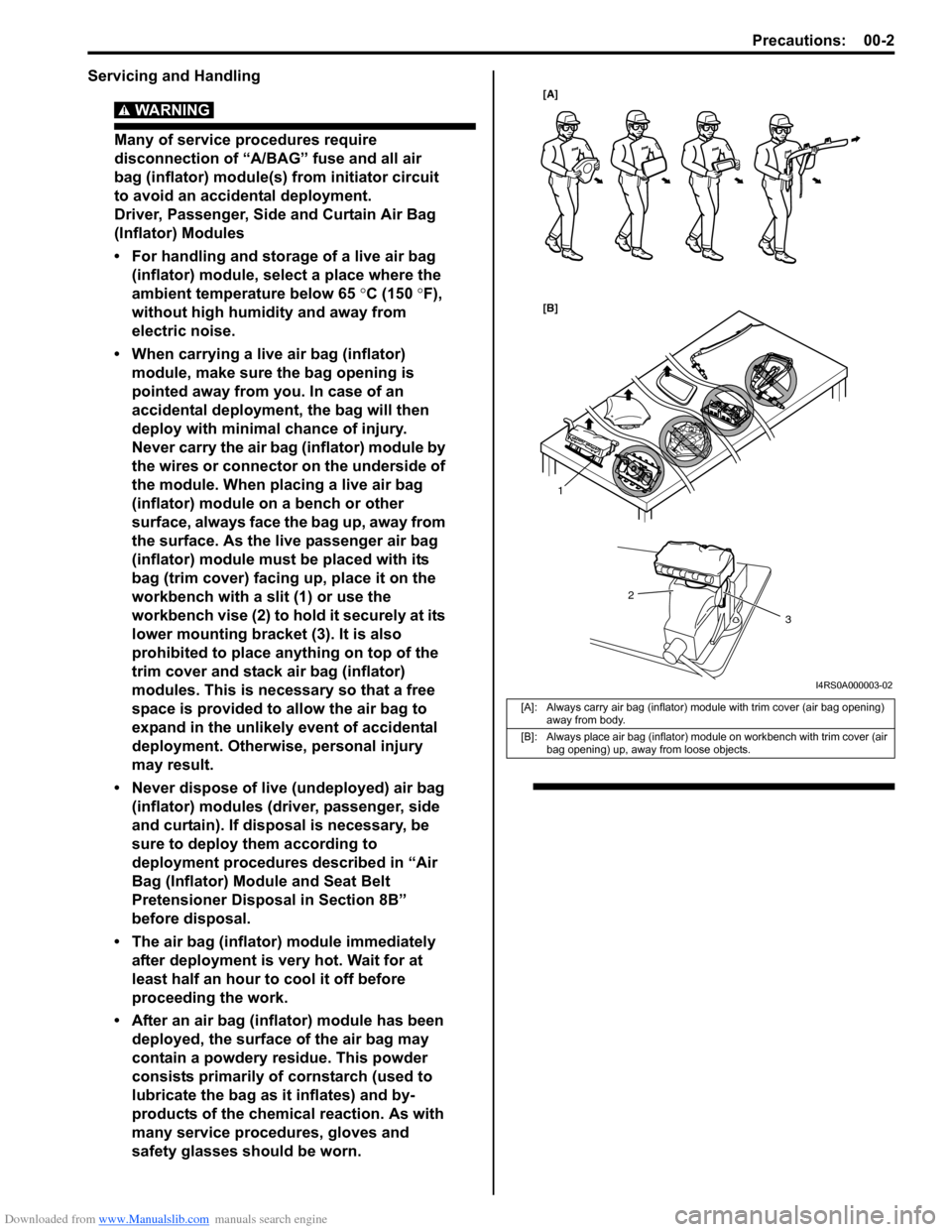
the module. When placing a live air bag
(inflator) module on a bench or other
surface, always face the bag up, away from
the surface. As the live passenger air bag
(inflator) module must be placed with its
bag (trim cover) facing up, place it on the
workbench with a slit (1) or use the
workbench vise (2) to hold it securely at its
lower mounting bracket (3). It is also
prohibited to place anything on top of the
trim cover and stack air bag (inflator)
modules. This is necessary so that a free
space is provided to allow the air bag to
expand in the unlikely event of accidental
deployment. Otherwise, personal injury
may result.
• Never dispose of live (undeployed) air bag (inflator) modules (driver, passenger, side
and curtain). If disposal is necessary, be
sure to deploy them according to
deployment procedures described in “Air
Bag (Inflator) Module and Seat Belt
Pretensioner Disposal in Section 8B”
before disposal.
• The air bag (inflator) module immediately
after deployment is very hot. Wait for at
least half an hour to cool it off before
proceeding the work.
• After an air bag (inflator) module has been deployed, the surface of the air bag may
contain a powdery residue. This powder
consists primarily of cornstarch (used to
lubricate the bag as it inflates) and by-
products of the chemical reaction. As with
many service procedures, gloves and
safety glasses should be worn.
[A]: Always carry air bag (inflator) module with trim cover (air bag opening) away from body.
[B]: Always place air bag (inflator) module on workbench with trim cover (air bag opening) up, away from loose objects.
1
2
3
[A]
[B]
I4RS0A000003-02
Page 8 of 1496
Downloaded from www.Manualslib.com manuals search engine 00-3 Precautions:
WARNING!
SDM
• For handling and storage of a SDM, select a place where the ambient temperature
below 65 °C (150 °F), without high humidity
and away from electric noise.
• During service procedures, be very careful when handling a Sensing and Diagnostic
Module (SDM). Never strike or jar the SDM.
• Never power up the air bag system when the SDM is not rigidly attached to the
vehicle. All SDM and mounting bracket
fasteners must be carefully torqued and
the arrow must be pointing toward the
front of the vehicle to ensure proper
operation of the air bag system.
The SDM could be activated when powered
while not rigidly att ached to the vehicle
which could cause deployment and result
in personal injury.
WARNING!
Driver and Passenger Seat Belt
Pretensioners
• For handling and storage of a live seat belt pretensioner, select a place where the
ambient temperature below 65 °C (150 ° F),
without high humidity and away from
electric noise.
• Never carry seat belt pretensioner by wire or connector of pretensioner. When
placing a live seat belt pretensioner on the
workbench or some place like that, never
put something on seat belt pretensioner.
Otherwise, personal injury may result.
• Never dispose of live (inactivated) seat belt pretensioners (drive and passenger). If
disposal is necessary, be sure to activate
them according to activation procedures
described in “Air Bag (Inflator) Module and
Seat Belt Pretensioner Disposal in Section
8B” before disposal.
• The seat belt pretensioner immediately after activation is very hot. Wait for at least
half an hour to cool it off before
proceeding the work.
• With many service procedures, gloves and safety glasses should be worn to prevent
any possible irritation of the skin or eyes.
• Even when the accident was light enough not to cause air bags to activate, be sure to inspect system
parts and other related parts according to instructions
under “Repair and Inspection Required after Accident
in Section 8B”.
• When servicing parts other than air bag system, if shocks may be applied to air bag system component
parts, remove those parts beforehand.
• When handling the air bag (inflator) modules (driver, passenger, side and curtain), seat belt pretensioners
(driver and passenger), forward sensor, side sensors
or SDM, be careful not to drop it or apply an impact to
it. If an excessive impact was applied, never attempt
disassembly or repair but replace it with a new one.
• When grease, cleaning agent, oil, water, etc. has got onto air bag (inflator) modules (driver, passenger, side
and curtain) or seat belt pretensioners (drive and
passenger), wipe off immediately with a dry cloth.
• Air bag wire harness is included in floor and instrument panel wire harnesses. Air bag wire
harness branched off from floor and instrument panel
wire harnesses can be identifie d easily as it is covered
with a yellow protection tube and it has yellow
connectors. Be very ca reful when handling it.
• When an open in air bag wire harness, damaged wire harness, connector or terminal is found, replace wire
harness, connectors and terminals as an assembly.
• Do not apply power to the air bag system unless all components are connected or a diagnostic flow
requests it, as this will set a DTC.
• Never use air bag system component parts from another vehicle.
• When using electric welding, be sure to disconnect all air bag (inflator) module connectors and pretensioner
connectors from air bag wire harness respectively.
• Never expose air bag system component parts directly to hot air (drying or baking the vehicle after
painting) or flames.
• WARNING / CAUTION labels are attached on each
part of air bag system components. Be sure to follow
the instructions.
• After vehicle is completely repaired, perform “Air Bag Diagnostic System Check in Section 8B”.
Page 30 of 1496
![SUZUKI SWIFT 2006 2.G Service Workshop Manual Downloaded from www.Manualslib.com manuals search engine 0A-9 General Information:
[A]
12
4 5
6
7 8
9
3
I4RS0B010002-03
1. Air bag label on driver air bag (inflator) module 6. Air bag label on SDM
2 SUZUKI SWIFT 2006 2.G Service Workshop Manual Downloaded from www.Manualslib.com manuals search engine 0A-9 General Information:
[A]
12
4 5
6
7 8
9
3
I4RS0B010002-03
1. Air bag label on driver air bag (inflator) module 6. Air bag label on SDM
2](/img/20/7607/w960_7607-29.png)
Downloaded from www.Manualslib.com manuals search engine 0A-9 General Information:
[A]
12
4 5
6
7 8
9
3
I4RS0B010002-03
1. Air bag label on driver air bag (inflator) module 6. Air bag label on SDM
2. Air bag label on combination switch and contact coil assembly7. Pretensioner label on seat belt retractor
3. Air bag label on passenger air bag (inflator) module 8. Child seat label (if equipped)
4. Air bag label on side air bag (inflator) module (if equipped) 9. Side/Curtain air bag label on pillar (both right and left sides) (if equipped)
5. Air bag label on curtain air bag (inflator) module (if equipped) [A]: These labels are attached on vehicle equipped with air ba g system only.
Page 76 of 1496
Downloaded from www.Manualslib.com manuals search engine 1A-26 Engine General Information and Diagnosis:
DTC CheckS7RS0B1104003
NOTE
• There are two types of OBD system depending on the vehicle specification.
For details, refer to “Precaution on On-
Board Diagnostic (OBD) System”.
• The MIL is turned on when the ECM and/or TCM detect malfunction(s). Each ECM and
TCM stores diagnostic information as the
diagnostic trouble code (DTC) in its
memory and outputs th e DTC to the scan
tool.
Therefore, check both of the ECM and TCM
for any DTC with the SUZUKI scan tool
because the DTC stored in ECM and TCM
is not read and displayed at a time.
However, each of the ECM and TCM needs
not to be checked with the generic scan
tool because the DTC stored in ECM and
TCM is read and displayed at a time.
Using Scan Tool
1) Prepare OBD generic scan tool or SUZUKI scan tool.
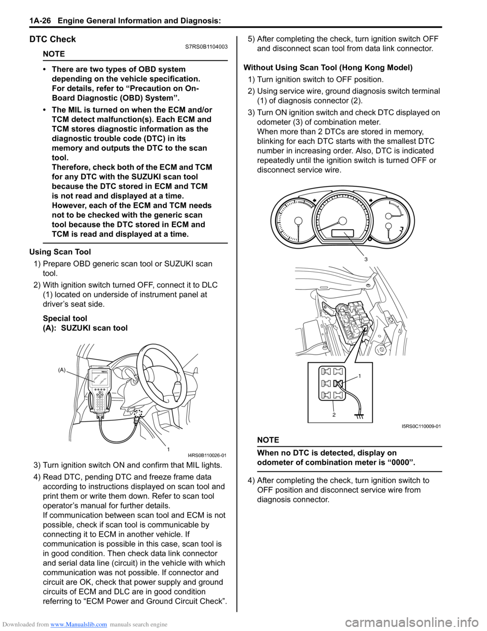
2) With ignition switch turned OFF, connect it to DLC (1) located on underside of instrument panel at
driver’s seat side.
Special tool
(A): SUZUKI scan tool
3) Turn ignition switch ON and confirm that MIL lights.
4) Read DTC, pending DTC and freeze frame data according to instructions displayed on scan tool and
print them or write them down. Refer to scan tool
operator’s manual for further details.
If communication between scan tool and ECM is not
possible, check if scan tool is communicable by
connecting it to ECM in another vehicle. If
communication is possible in this case, scan tool is
in good condition. Then check data link connector
and serial data line (circuit) in the vehicle with which
communication was not possible. If connector and
circuit are OK, check that power supply and ground
circuits of ECM and DLC are in good condition
referring to “ECM Power and Ground Circuit Check”. 5) After completing the check,
turn ignition switch OFF
and disconnect scan tool from data link connector.
Without Using Scan Tool (Hong Kong Model) 1) Turn ignition switch to OFF position.
2) Using service wire, ground diagnosis switch terminal (1) of diagnosis connector (2).
3) Turn ON ignition switch and check DTC displayed on
odometer (3) of combination meter.
When more than 2 DTCs are stored in memory,
blinking for each DTC star ts with the smallest DTC
number in increasing order. Also, DTC is indicated
repeatedly until the ignition switch is turned OFF or
disconnect service wire.
NOTE
When no DTC is detected, display on
odometer of combinatio n meter is “0000”.
4) After completing the check, turn ignition switch to
OFF position and disconnect service wire from
diagnosis connector.
(A)
1
I4RS0B110026-01
21
3
I5RS0C110009-01
Page 471 of 1496
Downloaded from www.Manualslib.com manuals search engine Wheels and Tires: 2D-4
Radial Tire Waddle DescriptionS7RS0B2401005
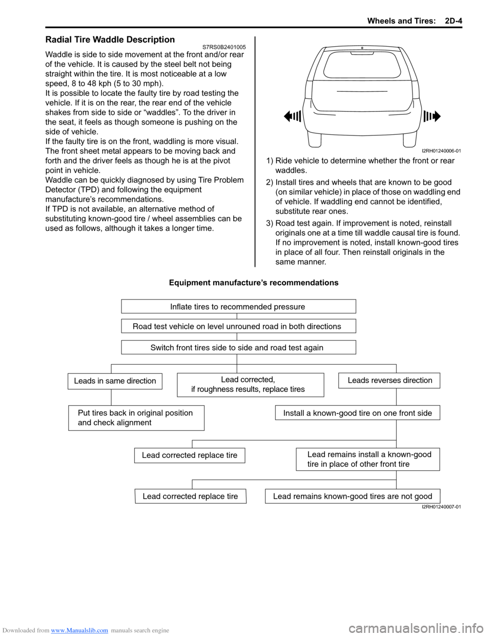
Waddle is side to side movement at the front and/or rear
of the vehicle. It is caused by the steel belt not being
straight within the tire. It is most noticeable at a low
speed, 8 to 48 kph (5 to 30 mph).
It is possible to locate the f aulty tire by road testing the
vehicle. If it is on the rear , the rear end of the vehicle
shakes from side to side or “waddles”. To the driver in
the seat, it feels as though someone is pushing on the
side of vehicle.
If the faulty tire is on the front, waddling is more visual.
The front sheet metal appears to be moving back and
forth and the driver feels as though he is at the pivot
point in vehicle.
Waddle can be quickly diagnosed by using Tire Problem
Detector (TPD) and following the equipment
manufacture’s recommendations.
If TPD is not available, an alternative method of
substituting known-good tire / wheel assemblies can be
used as follows, although it takes a longer time. 1) Ride vehicle to determine whether the front or rear
waddles.
2) Install tires and wheels that are known to be good (on similar vehicle) in place of those on waddling end
of vehicle. If waddling end cannot be identified,
substitute rear ones.
3) Road test again. If improvement is noted, reinstall originals one at a time till w addle causal tire is found.
If no improvement is noted, install known-good tires
in place of all four. Then reinstall originals in the
same manner.
Equipment manufacture’s recommendations
I2RH01240006-01
Inflate tires to recommended pressure
Road test vehicle on level unrouned road in both directions
Switch front tires side to side and road test again
Lead corrected,
if roughness results, replace tiresLeads in same directionLeads reverses direction
Put tires back in original position
and check alignmentInstall a known-good tire on one front side
Lead remains install a known-good
tire in place of other front tire
Lead remains known-good tires are not goodLead corrected replace tire
Lead corrected replace tire
I2RH01240007-01
Page 488 of 1496
Downloaded from www.Manualslib.com manuals search engine 3A-10 Drive Shaft / Axle:
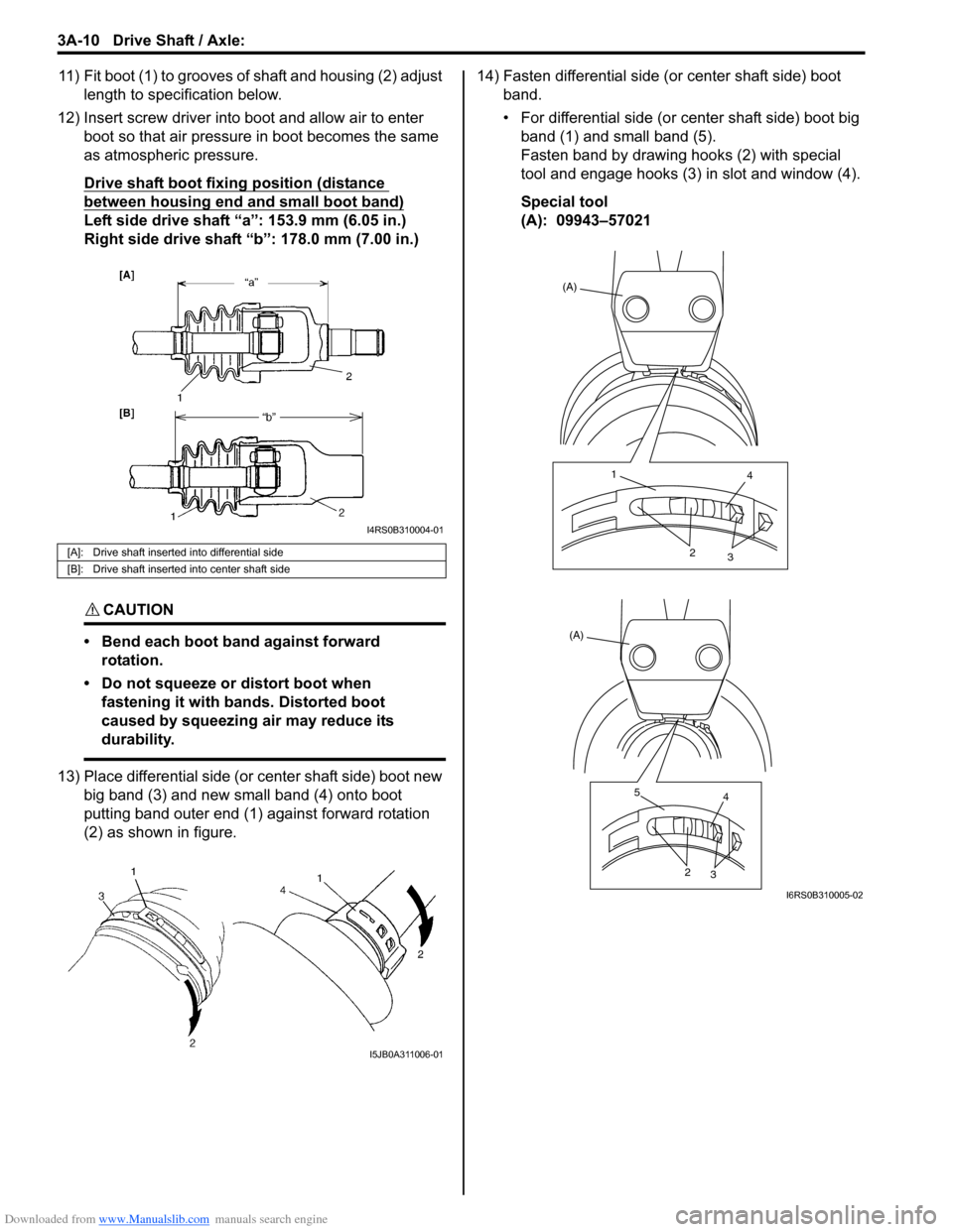
11) Fit boot (1) to grooves of shaft and housing (2) adjust
length to specification below.
12) Insert screw driver into boot and allow air to enter boot so that air pressure in boot becomes the same
as atmospheric pressure.
Drive shaft boot fixing position (distance
between housing end and small boot band)
Left side drive shaft “a”: 153.9 mm (6.05 in.)
Right side drive shaft “b”: 178.0 mm (7.00 in.)
CAUTION!
• Bend each boot band against forward rotation.
• Do not squeeze or distort boot when fastening it with bands. Distorted boot
caused by squeezing air may reduce its
durability.
13) Place differential side (or center shaft side) boot new big band (3) and new small band (4) onto boot
putting band outer end (1) against forward rotation
(2) as shown in figure. 14) Fasten differential side (or center shaft side) boot
band.
• For differential side (or center shaft side) boot big band (1) and small band (5).
Fasten band by drawing hooks (2) with special
tool and engage hooks (3) in slot and window (4).
Special tool
(A): 09943–57021
[A]: Drive shaft inserted into differential side
[B]: Drive shaft inserted into center shaft side
I4RS0B310004-01
I5JB0A311006-01
(A)
1 4
2 3
(A)
5 4
2 3
I6RS0B310005-02
Page 489 of 1496
Downloaded from www.Manualslib.com manuals search engine Drive Shaft / Axle: 3A-11
DOJ
Judging from abnormality noted before disassembly and
what is found through visual check of components parts
after disassembly, prepare replacing parts and proceed
to reassembly.
Make sure that wheel side joint assembly and DOJ
housing are washed thoroughly and air dried.
Replace boot(s) with new one(s).
CAUTION!
• Do not wash boots in degreaser such as gasoline or kerosene. etc. Washing in
degreaser causes deterioration of boot.
• To ensure full performance of joint as designed, be sure to distinguish between
two types of grease in repair set and apply
specified volume to respective joint
referring to the followings for identification
of the grease.
1) Wash disassembled parts (except boots). After washing, dry parts completely by blowing air.
2) Clean boots with cloth.
3) Apply grease to wheel side joint. Use specified
grease in tube in wheel side boot set as a spare
parts.
Grease color
: Black
Amount
: 55 – 75 g (1.9 – 2.6 oz)
4) Install wheel side boot on shaft.
5) Fill up boot inside wi th specified grease.
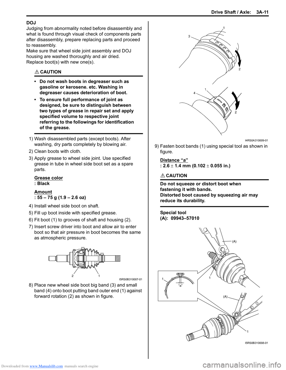
6) Fit boot (1) to grooves of shaft and housing (2).
7) Insert screw driver into boot and allow air to enter boot so that air pressure in boot becomes the same
as atmospheric pressure.
8) Place new wheel side boot big band (3) and small band (4) onto boot putting band outer end (1) against
forward rotation (2) as shown in figure. 9) Fasten boot bands (1) using special tool as shown in
figure.
Distance “a”
: 2.6 ± 1.4 mm (0.102 ± 0.055 in.)
CAUTION!
Do not squeeze or distort boot when
fastening it with bands.
Distorted boot caused by squeezing air may
reduce its durability.
Special tool
(A): 09943–57010
21I5RS0B310007-01
I4RS0A310009-01
(A)
1
(A)
1
“a”
1
I5RS0B310008-01
Page 490 of 1496
Downloaded from www.Manualslib.com manuals search engine 3A-12 Drive Shaft / Axle:
10) Set new differential side (or center shaft side) small band and new differential side (or center shaft side)
boot on shaft temporarily.
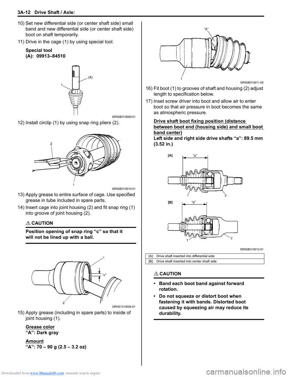
11) Drive in the cage (1) by using special tool.
Special tool
(A): 09913–84510
12) Install circlip (1) by using snap ring pliers (2).
13) Apply grease to entire su rface of cage. Use specified
grease in tube included in spare parts.
14) Insert cage into joint housing (2) and fit snap ring (1) into groove of joint housing (2).
CAUTION!
Position opening of snap ring “c” so that it
will not be lined up with a ball.
15) Apply grease (including in spare parts) to inside of joint housing (1).
Grease color
“A”: Dark gray
Amount
“A”: 70 – 90 g (2.5 – 3.2 oz) 16) Fit boot (1) to grooves of shaft and housing (2) adjust
length to specification below.
17) Inset screw driver into boot and allow air to enter boot so that air pressure in boot becomes the same
as atmospheric pressure.
Drive shaft boot fixing position (distance
between boot end (housing side) and small boot
band center)
Left side and right side drive shafts “a”: 89.5 mm
(3.52 in.)
CAUTION!
• Band each boot band against forward rotation.
• Do not squeeze or distort boot when fastening it with bands. Distorted boot
caused by squeezing air may reduce its
durability.
(A)
1
I5RS0B310009-01
I5RS0B310010-01
I2RH01310036-01
[A]: Drive shaft inserted into differential side
[B]: Drive shaft inserted into center shaft side
I5RS0B310011-02
I5RS0B310012-01
Page 544 of 1496
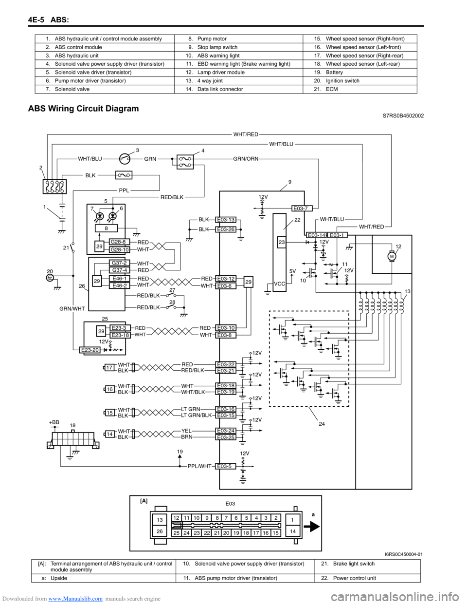
Downloaded from www.Manualslib.com manuals search engine 4E-5 ABS:
ABS Wiring Circuit DiagramS7RS0B4502002
1. ABS hydraulic unit / control module assembly 8.
Pump motor 15. Wheel speed sensor (Right-front)
2. ABS control module 9. Stop lamp switch 16. Wheel speed sensor (Left-front)
3. ABS hydraulic unit 10. ABS warning light 17. Wheel speed sensor (Right-rear)
4. Solenoid valve power supply driver (transistor) 11. EBD warnin g light (Brake warning light) 18. Wheel speed sensor (Left-rear)
5. Solenoid valve driver (transistor) 12. Lamp driver module 19. Battery
6. Pump motor driver (transistor) 13. 4 way joint 20. Ignition switch
7. Solenoid valve 14. Data link connector 21. ECM
[A]
14
1516171819202122232425 1
23456789101112
13
26 E03
a
WHT/BLU
BLKWHT/BLU
M
12V
9
10 11 12
13
BLKE03-14E03-1
E03-13
E03-26
YELBRN
14E03-24
LT GRN/BLKLT GRN
15
WHTWHT/BLK
16
RED
WHTBLK
WHTBLK
WHTBLK
WHTBLKRED/BLK
17
12V
PPL/WHT
18E03-5
1912V
5V
12V
23
24
VCC22
E03-25
E03-15E03-16
E03-19E03-18
E03-22E03-21
WHT/RED
WHT/RED
+BB
GRN/ORN
E03-7
WHT/BLUGRN
1
2
3
4
8
RED/BLK
E03-12
E03-6
RED
WHTE03-10E03-8
REDWHT
20 7
6
529
29
G28-8
G28-10
25
29
E23-3E23-18
GRN/WHT
21
PPL
12V
E23-20
12V
12V
12V
12V
REDWHTE46-1
E46-2
BLK
RED/BLK
RED/BLK
RED
RED
WHT
WHT
27
28
26
29
G37-2
G37-4
REDWHT
I6RS0C450004-01
[A]: Terminal arrangement of ABS hydraulic unit / control module assembly 10. Solenoid valve power supply driver
(transistor) 21. Brake light switch
a: Upside 11. ABS pump motor driver (transistor) 22. Power control unit