front door glass removal and installation SUZUKI SWIFT 2006 2.G Service Workshop Manual
[x] Cancel search | Manufacturer: SUZUKI, Model Year: 2006, Model line: SWIFT, Model: SUZUKI SWIFT 2006 2.GPages: 1496, PDF Size: 34.44 MB
Page 1169 of 1496

Downloaded from www.Manualslib.com manuals search engine Table of Contents 9-iii
Door Switch (Front / Rear Door) Inspection ...... 9C-17
Rear End Door Switch Inspection ..................... 9C-17
Outside Air Temperature Sensor Removal and Installation (If Equipped) .......................... 9C-17
Outside Air Temperature Sensor Inspection (If Equipped) ................................................... 9C-17
Instrument Panel Removal and Installation....... 9C-18
Information Display (Clock) Removal and Installation ....................................................... 9C-19
Audio Unit Removal and In stallation ................. 9C-19
Front Speaker Removal and Installation ........... 9C-19
Rear Speaker Removal and Installation............ 9C-20
Horn Removal and Installation .......................... 9C-20
Horn Inspection ................................................. 9C-20
Horn Relay Inspection ....................................... 9C-20
Antenna Amplifier Removal and Installation ..... 9C-21
Remote Audio Control Switch Removal and Installation (If Equipped) ................................. 9C-21
Remote Audio Control Switch Inspection (If Equipped)........................................................ 9C-22
Vehicle Speed Signal Inspection (For Audio Unit) (If Equipped) ........................................... 9C-22
Specifications ..................................................... 9C-22
Tightening Torque Specifications ...................... 9C-22
Wipers / Washers............ ......................... 9D-1
Diagnostic Information and Procedures ............ 9D-1
Front Wiper and Washer Symptom Diagnosis .... 9D-1
Rear Wiper and Washer Symptom Diagnosis..... 9D-1
Repair Instructions .............................................. 9D-2 Wipers and Washers Components ..................... 9D-2
Washer Tank and Washer Pump Removal and Installation .................................................. 9D-3
Washer Pump Inspection .................................... 9D-3
Windshield Wiper Removal and Installation ........ 9D-4
Windshield Wiper Motor Inspection..................... 9D-5
Rear Wiper Removal and Installation.................. 9D-6
Rear Wiper Motor Inspection .............................. 9D-7
Windshield Wiper and Washer Switch Removal and Installation................................... 9D-7
Windshield Wiper and Washer Switch Inspection.......................................................... 9D-8
Rear Wiper and Washer Switch Removal and Installation ......................................................... 9D-9
Rear Wiper and Washer Switch Inspection......... 9D-9
Rear Wiper Relay Removal and Installation ..... 9D-10
Rear Wiper Relay Inspection ............................ 9D-10
Specifications ..................................................... 9D-10
Tightening Torque Specifications ...................... 9D-10
Glass / Windows / Mirrors.. ..................... 9E-1
General Description ............................................. 9E-1
Rear End Door Window Defogger System Description ........................................................ 9E-1
Windshield Construction ..................................... 9E-1
Diagnostic Information and Procedures ............ 9E-2 Rear End door Window Defogger Symptom Diagnosis .......................................................... 9E-2 Power Window Control System Symptom
Diagnosis .......................................................... 9E-2
Power Door Mirror Control System Symptom Diagnosis .......................................................... 9E-3
Door Mirror Heater Symptom Diagnosis (If
Equipped) .......................................................... 9E-3
Repair Instructions ........... ................................... 9E-4
Windshield Removal and In stallation .................. 9E-4
Front Door Window Components ........................ 9E-8
Front Door Glass Removal and Installation ........ 9E-8
Front Door Window Re gulator Removal and
Installation ......................................................... 9E-9
Front Door Window Regula tor Inspection ......... 9E-10
Rear Door Window Components ...................... 9E-10
Rear Door Glass Removal and Installation ....... 9E-11
Rear Door Window Regulator Removal and Installation ....................................................... 9E-12
Rear Door Window Regulato r Inspection .......... 9E-12
Rear End Door Window Components ............... 9E-13
Rear End Door Glass Removal and Installation ....................................................... 9E-13
Rear End Door Window Defogger Switch Inspection ........................................................ 9E-14
Rear End Door Window Defogger Relay Inspection ........................................................ 9E-14
Rear End Door Window Defogger Wire Inspection ........................................................ 9E-15
Rear End Door Window Defogger Wire
Repair.............................................................. 9E-15
Power Window Main Switch Inspection ............ 9E-16
Power Window Sub Switch Inspection .............. 9E-17
Door Mirror Components.. ................................. 9E-18
Door Mirror Removal and In stallation................ 9E-18
Power Door Mirror Switch Inspection ................ 9E-18
Power Door Mirror Actuator Inspection ............. 9E-19
Door Mirror Heater Switch Inspection (If Equipped) ........................................................ 9E-19
Door Mirror Heater Inspec tion (If Equipped) ..... 9E-19
Special Tools and Equipmen t ........................... 9E-19
Recommended Service Material ....................... 9E-19
Security and Locks......... ..........................9F-1
General Description ............................................. 9F-1
Key Coding Construction .................................... 9F-1
Rear End Door Opener System Description ....... 9F-1
Component Location ............ ............................... 9F-2
Power Door Lock and Keyless Entry System
Component Location ......................................... 9F-2
Diagnostic Information and Procedures ............ 9F-3 Power Door Lock System Symptom Diagnosis .......................................................... 9F-3
Power Door Lock System Operation Inspection .......................................................... 9F-3
Keyless Entry System Symptom Diagnosis (If
Equipped) .......................................................... 9F-4
Keyless Entry System Operation Inspection ....... 9F-5
Door Lock Function of Keyless Start System Symptom Diagnosis (If Equipped)..................... 9F-5
Page 1314 of 1496
Downloaded from www.Manualslib.com manuals search engine 9C-19 Instrumentation / Driver Info. / Horn:
Installation
Reverse removal procedure noting the following.
• When installing each part, be careful not to catch any
cable or wiring harness.
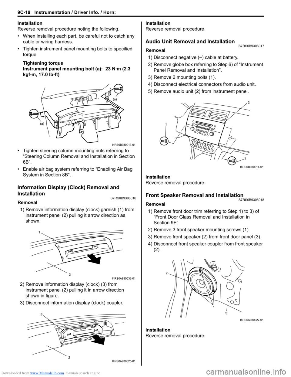
• Tighten instrument panel mounting bolts to specified
torque
Tightening torque
Instrument panel mounting bolt (a): 23 N·m (2.3
kgf-m, 17.0 lb-ft)
• Tighten steering column mounting nuts referring to “Steering Column Removal an d Installation in Section
6B”.
• Enable air bag system referring to “Enabling Air Bag System in Section 8B”.
Information Display (Clock) Removal and
Installation
S7RS0B9306016
Removal
1) Remove information display (clock) garnish (1) from instrument panel (2) pulling it arrow direction as
shown.
2) Remove information di splay (clock) (3) from
instrument panel (2) pulli ng it in arrow direction
shown in figure.
3) Disconnect information display (clock) coupler. Installation
Reverse removal procedure.
Audio Unit Removal and InstallationS7RS0B9306017
Removal
1) Disconnect negative (–) cable at battery.
2) Remove globe box referring to Step 6) of “Instrument Panel Removal and Installation”.
3) Remove 2 mounting bolts (1).
4) Disconnect electrical connectors from audio unit.
5) Remove audio unit (2) from instrument panel.
Installation
Reverse removal procedure.
Front Speaker Removal and InstallationS7RS0B9306018
Removal 1) Remove front door trim refe rring to Step 1) to 3) of
“Front Door Glass Remo val and Installation in
Section 9E”.
2) Remove 3 front speaker mounting screws (1).
3) Remove front speaker (2) from front door panel (3).
4) Disconnect front speaker coupler from front speaker (2).
Installation
Reverse removal procedure.
(a) (a)
I4RS0B930013-01
1
2I4RS0A930032-01
3
2I4RS0A930025-01
2
1
1
I4RS0B930014-01
1
2
3
I4RS0A930027-01
Page 1315 of 1496
Downloaded from www.Manualslib.com manuals search engine Instrumentation / Driver Info. / Horn: 9C-20
Rear Speaker Removal and InstallationS7RS0B9306019
Removal
1) Remove rear door trim referring to Step 1) to 3) of “Rear Door Glass Removal and Installation in
Section 9E”.
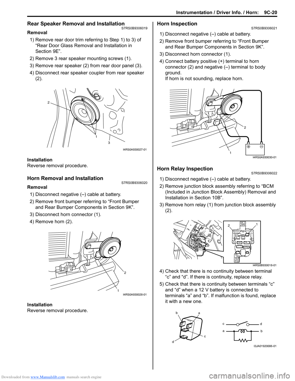
2) Remove 3 rear speaker mounting screws (1).
3) Remove rear speaker (2) from rear door panel (3).
4) Disconnect rear speaker coupler from rear speaker (2).
Installation
Reverse removal procedure.
Horn Removal and InstallationS7RS0B9306020
Removal 1) Disconnect negative (–) cable at battery.
2) Remove front bumper referring to “Front Bumper and Rear Bumper Components in Section 9K”.
3) Disconnect horn connector (1).
4) Remove horn (2).
Installation
Reverse removal procedure.
Horn InspectionS7RS0B9306021
1) Disconnect negative (–) cable at battery.
2) Remove front bumper referring to “Front Bumper and Rear Bumper Components in Section 9K”.
3) Disconnect horn connector (1).
4) Connect battery positive (+) terminal to horn
connector (2) and negative (–) terminal to body
ground.
If horn is not sounding, replace horn.
Horn Relay InspectionS7RS0B9306022
1) Disconnect negative (–) cable at battery.
2) Remove junction block assembly referring to “BCM (Included in Junction Bl ock Assembly) Removal and
Installation in Section 10B”.
3) Remove horn relay (1) from junction block assembly (2).
4) Check that there is no continuity between terminal “c” and “d”. If there is continuity, replace relay.
5) Check that there is continuity between terminals “c” and “d” when a 12 V battery is connected to
terminals “a” and “b”. If malfunction is found, replace
it with a new one.
1
2
3
I4RS0A930027-01
12I4RS0A930028-01
1 2I4RS0A930030-01
1
2
I4RS0B930018-01
ba
c
d c
a
d
bI3JA01920006-01
Page 1335 of 1496
Downloaded from www.Manualslib.com manuals search engine Glass / Windows / Mirrors: 9E-8
Front Door Window ComponentsS7RS0B9506002
Front Door Glass Removal and InstallationS7RS0B9506003
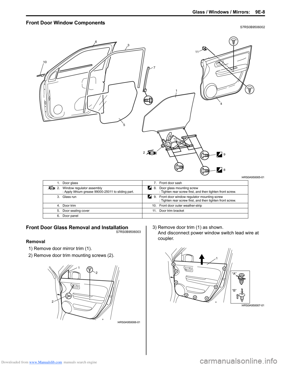
Removal1) Remove door mirror trim (1).
2) Remove door trim mounting screws (2). 3) Remove door trim (1) as shown.
And disconnect power window switch lead wire at
coupler.
10 6
3
1
7
11
5
2 9
8
4
I4RS0A950005-01
1. Door glass 7. Front door sash
2. Window regulator assembly : Apply lithium grease 99000-25011 to sliding part. 8. Door glass mounting screw
: Tighten rear screw first, and then tighten front screw.
3. Glass run 9. Front door window regulator mounting screw
: Tighten rear screw first, and then tighten front screw.
4. Door trim 10. Front door outer weather-strip
5. Door sealing cover 11. Door trim bracket
6. Door panel
2 2
1
I4RS0A950006-01
“B”
“A”
“B”
“A”
“B”“A”
“A”
“A”“A”“A”
1
I4RS0A950007-01
Page 1336 of 1496
Downloaded from www.Manualslib.com manuals search engine 9E-9 Glass / Windows / Mirrors:
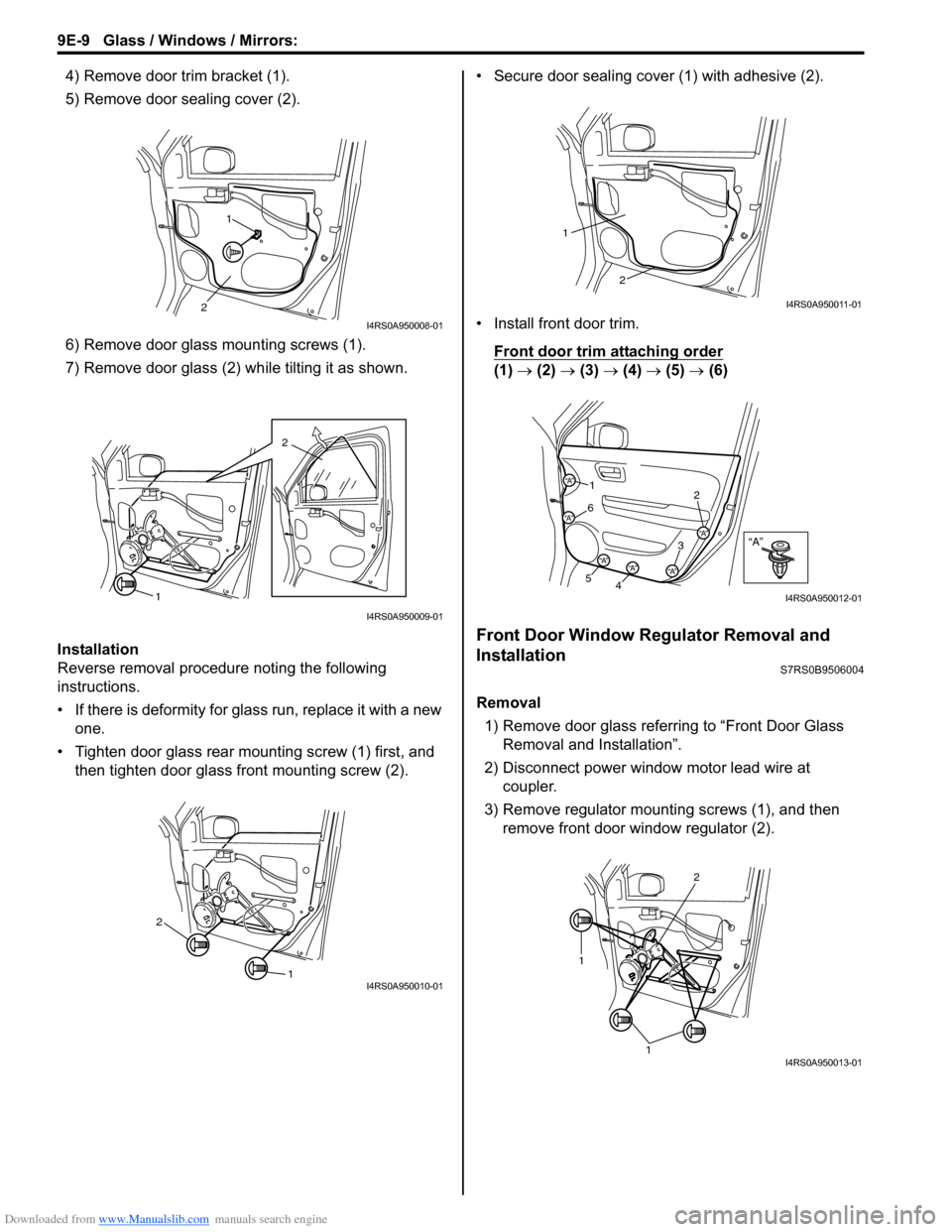
4) Remove door trim bracket (1).
5) Remove door sealing cover (2).
6) Remove door glass mounting screws (1).
7) Remove door glass (2) while tilting it as shown.
Installation
Reverse removal procedure noting the following
instructions.
• If there is deformity for glass run, replace it with a new one.
• Tighten door glass rear mounting screw (1) first, and then tighten door glass front mounting screw (2). • Secure door sealing cover (1) with adhesive (2).
• Install front door trim.
Front door trim attaching order
(1) → (2) → (3) → (4) → (5) → (6)
Front Door Window Regulator Removal and
Installation
S7RS0B9506004
Removal
1) Remove door glass referring to “Front Door Glass Removal and Installation”.
2) Disconnect power window motor lead wire at coupler.
3) Remove regulator mounting screws (1), and then remove front door window regulator (2).
1
2
I4RS0A950008-01
2
1
I4RS0A950009-01
1
2
I4RS0A950010-01
2
1
I4RS0A950011-01
“A”“A”
“A”
“A”
“A”“A”“A”
1 2
3
4
5 6
I4RS0A950012-01
1
1
2
I4RS0A950013-01
Page 1337 of 1496
Downloaded from www.Manualslib.com manuals search engine Glass / Windows / Mirrors: 9E-10
Installation
Reverse removal procedure noting the following
instruction.
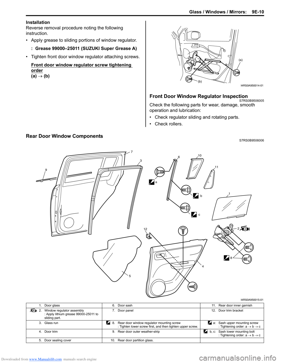
• Apply grease to sliding portions of window regulator.: Grease 99000–25011 (SUZUKI Super Grease A)
• Tighten front door window regulator attaching screws. Front door window regulator screw tightening
order
(a) → (b)
Front Door Window Regulator InspectionS7RS0B9506005
Check the following parts for wear, dama ge, smooth
operation and lubrication:
• Check regulator sliding and rotating parts.
• Check rollers.
Rear Door Window ComponentsS7RS0B9506006
(a)
(b)
I4RS0A950014-01
9
7
3610
11
b
c
12
5 2
8
4
a
1
I4RS0A950015-01
1. Door glass
6. Door sash 11. Rear door inner garnish
2. Window regulator assembly : Apply lithium grease 99000-25011 to
sliding part. 7. Door panel
12. Door trim bracket
3. Glass run 8. Rear door window regulator mounting screw
: Tighten lower screw first, and then tighten upper screw. a: Sash upper mounting screw
: Tightening order: a → b → c
4. Door trim 9. Rear door outer weather-strip b, c: Sash lower mounting bolt
: Tightening order: a → b → c
5. Door sealing cover 10. Rear door partition glass.
Page 1343 of 1496
Downloaded from www.Manualslib.com manuals search engine Glass / Windows / Mirrors: 9E-16
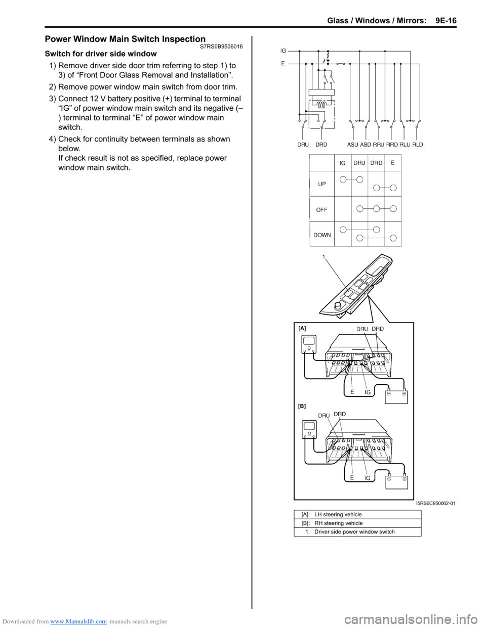
Power Window Main Switch InspectionS7RS0B9506016
Switch for driver side window 1) Remove driver side door trim referring to step 1) to 3) of “Front Door Glass Removal and Installation”.
2) Remove power window main switch from door trim.
3) Connect 12 V battery positive (+) terminal to terminal “IG” of power window main switch and its negative (–
) terminal to terminal “E” of power window main
switch.
4) Check for continuity between terminals as shown below.
If check result is not as specified, replace power
window main switch.
[A]: LH steering vehicle
[B]: RH steering vehicle
1. Driver side power window switch
I5RS0C950002-01
Page 1344 of 1496
Downloaded from www.Manualslib.com manuals search engine 9E-17 Glass / Windows / Mirrors:
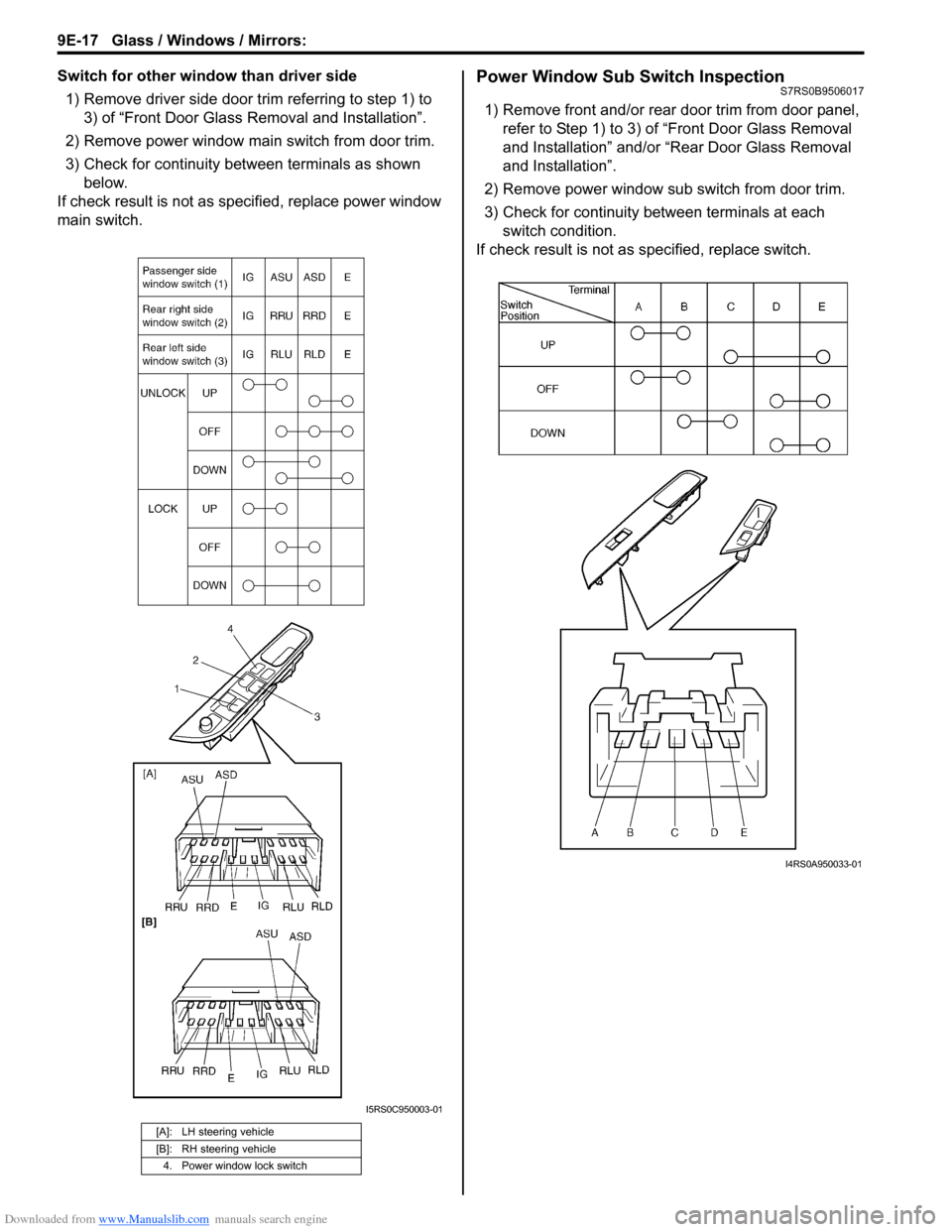
Switch for other window than driver side1) Remove driver side door trim referring to step 1) to 3) of “Front Door Glass Removal and Installation”.
2) Remove power window main switch from door trim.
3) Check for continuity between terminals as shown below.
If check result is not as sp ecified, replace power window
main switch.Power Window Sub Switch InspectionS7RS0B9506017
1) Remove front and/or rear door trim from door panel, refer to Step 1) to 3) of “Front Door Glass Removal
and Installation” and/or “Rear Door Glass Removal
and Installation”.
2) Remove power window sub switch from door trim.
3) Check for continuity between terminals at each switch condition.
If check result is not as specified, replace switch.
[A]: LH steering vehicle
[B]: RH steering vehicle
4. Power window lock switch
I5RS0C950003-01
I4RS0A950033-01
Page 1345 of 1496
Downloaded from www.Manualslib.com manuals search engine Glass / Windows / Mirrors: 9E-18
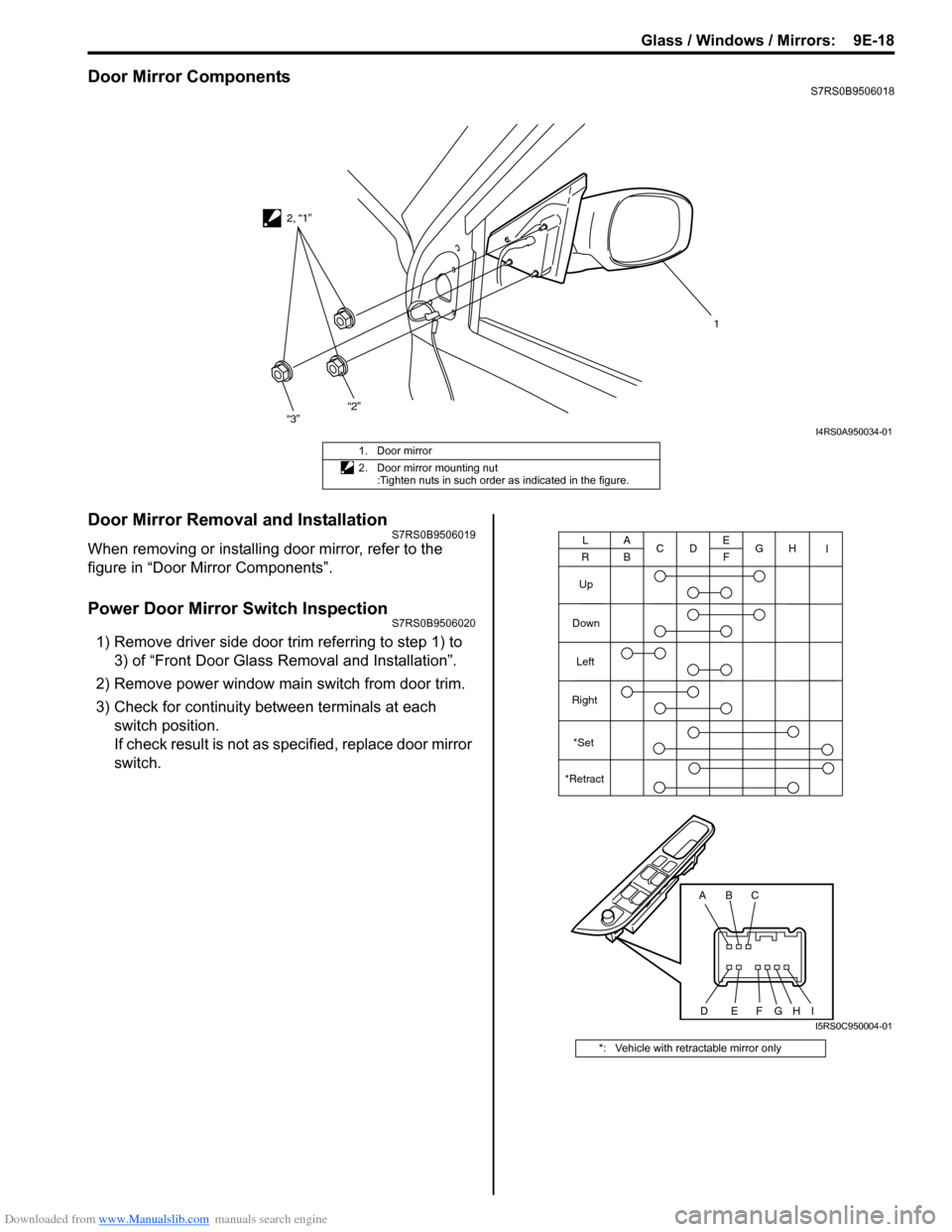
Door Mirror ComponentsS7RS0B9506018
Door Mirror Removal and InstallationS7RS0B9506019
When removing or installing door mirror, refer to the
figure in “Door Mirror Components”.
Power Door Mirror Switch InspectionS7RS0B9506020
1) Remove driver side door trim referring to step 1) to 3) of “Front Door Glass Removal and Installation”.
2) Remove power window main switch from door trim.
3) Check for continuity between terminals at each switch position.
If check result is not as specified, replace door mirror
switch.
1
2, “1”
“3”
“2”
I4RS0A950034-01
1. Door mirror
2. Door mirror mounting nut
:Tighten nuts in such order as indicated in the figure.
*: Vehicle with retractable mirror only
ABC
DEFG
A
B C
D E
F G
Up
Down Left
Right
L
RH I
*Set
*Retract
HII5RS0C950004-01
Page 1346 of 1496
Downloaded from www.Manualslib.com manuals search engine 9E-19 Glass / Windows / Mirrors:
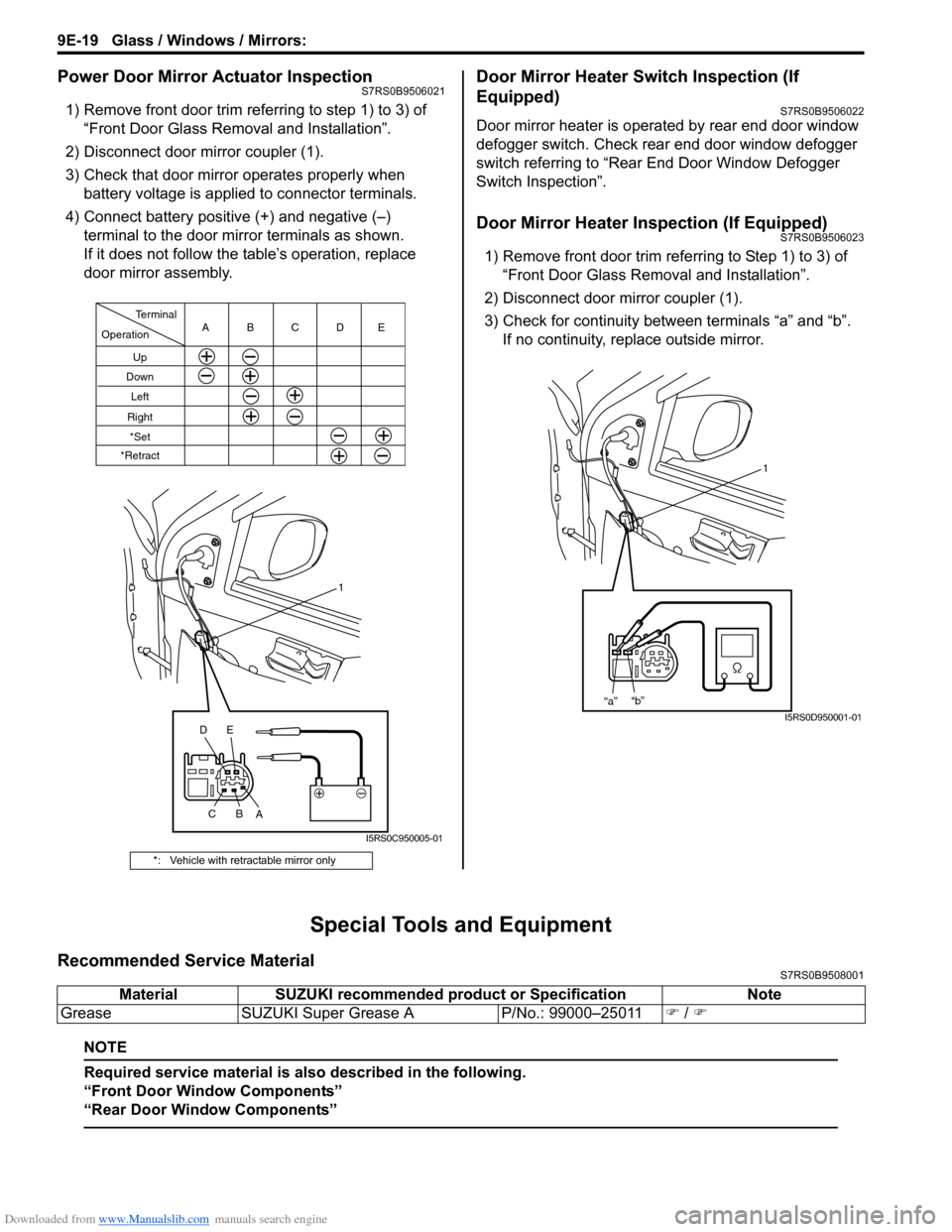
Power Door Mirror Actuator InspectionS7RS0B9506021
1) Remove front door trim referring to step 1) to 3) of “Front Door Glass Removal and Installation”.
2) Disconnect door mirror coupler (1).
3) Check that door mirror operates properly when battery voltage is applied to connector terminals.
4) Connect battery positive (+) and negative (–) terminal to the door mirror terminals as shown.
If it does not follow the table’s operation, replace
door mirror assembly.
Door Mirror Heater Switch Inspection (If
Equipped)
S7RS0B9506022
Door mirror heater is operated by rear end door window
defogger switch. Check rear end door window defogger
switch referring to “Rear End Door Window Defogger
Switch Inspection”.
Door Mirror Heater Inspection (If Equipped)S7RS0B9506023
1) Remove front door trim refe rring to Step 1) to 3) of
“Front Door Glass Removal and Installation”.
2) Disconnect door mirror coupler (1).
3) Check for continuity between terminals “a” and “b”. If no continuity, replace outside mirror.
Special Tools and Equipment
Recommended Service MaterialS7RS0B9508001
NOTE
Required service material is also described in the following.
“Front Door Window Components”
“Rear Door Window Components”
*: Vehicle with retractable mirror only
Operation
Terminal
Up
Down
Left
RightCBA
1
C B
A
*Set
*Retract
DE
DE
I5RS0C950005-01
1
“a” “b”
I5RS0D950001-01
Material
SUZUKI recommended product or Specification Note
Grease SUZUKI Super Grease A P/No.: 99000–25011�) / �)