wheel bearing replacement SUZUKI SWIFT 2006 2.G Service Workshop Manual
[x] Cancel search | Manufacturer: SUZUKI, Model Year: 2006, Model line: SWIFT, Model: SUZUKI SWIFT 2006 2.GPages: 1496, PDF Size: 34.44 MB
Page 21 of 1496

Downloaded from www.Manualslib.com manuals search engine Table of Contents 0- i
0
Section 0
CONTENTS
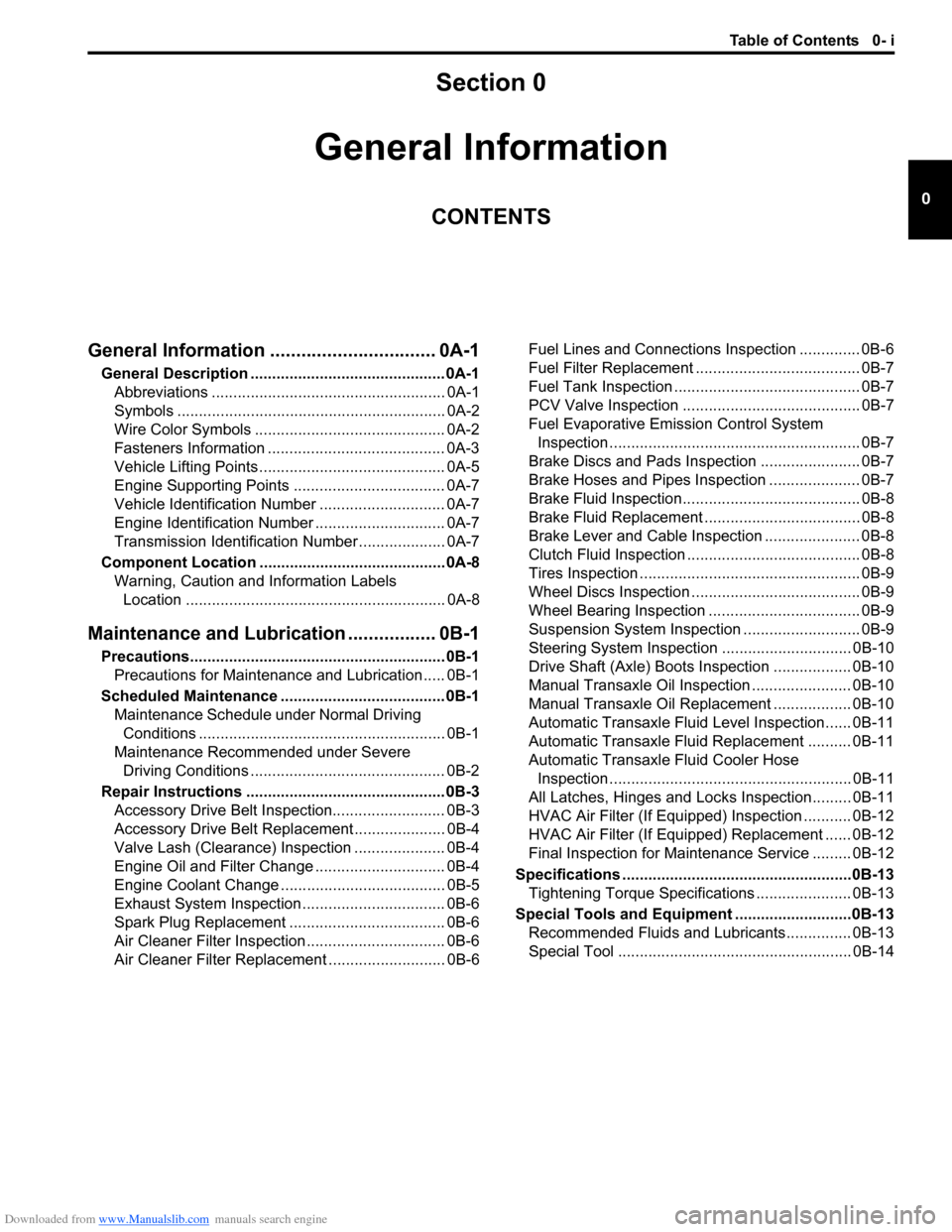
General Information
General Information ................................ 0A-1
General Description ............................................. 0A-1
Abbreviations ...................................................... 0A-1
Symbols .............................................................. 0A-2
Wire Color Symbols ............................................ 0A-2
Fasteners Information ......................................... 0A-3
Vehicle Lifting Points ........................................... 0A-5
Engine Supporting Points ................................... 0A-7
Vehicle Identification Number ............................. 0A-7
Engine Identification Number .............................. 0A-7
Transmission Identification Number .................... 0A-7
Component Locatio n ........................................... 0A-8
Warning, Caution and Information Labels Location ............................................................ 0A-8
Maintenance and Lubricat ion ................. 0B-1
Precautions........................................................... 0B-1
Precautions for Maintenance and Lubrication ..... 0B-1
Scheduled Maintenance ...................................... 0B-1 Maintenance Schedule under Normal Driving Conditions ......................................................... 0B-1
Maintenance Recommended under Severe Driving Conditions ............................................. 0B-2
Repair Instructions .............................................. 0B-3 Accessory Drive Belt Inspection.......................... 0B-3
Accessory Drive Belt Repl acement ..................... 0B-4
Valve Lash (Clearance) Inspection ..................... 0B-4
Engine Oil and Filter Change .............................. 0B-4
Engine Coolant Change ...... ................................ 0B-5
Exhaust System Inspection ................................. 0B-6
Spark Plug Replacement .................................... 0B-6
Air Cleaner Filter Inspection ................................ 0B-6
Air Cleaner Filter Replac ement ........................... 0B-6 Fuel Lines and Connections Inspection .............. 0B-6
Fuel Filter Replacement ...................................... 0B-7
Fuel Tank Inspection ........................................... 0B-7
PCV Valve Inspection ......................................... 0B-7
Fuel Evaporative Emission Control System
Inspection .......................................................... 0B-7
Brake Discs and Pads Inspection ....................... 0B-7
Brake Hoses and Pipes Inspection ..................... 0B-7
Brake Fluid Inspection......................................... 0B-8
Brake Fluid Replacement .................................... 0B-8
Brake Lever and Cable Inspection ...................... 0B-8
Clutch Fluid Inspection ........................................ 0B-8
Tires Inspection ................................................... 0B-9
Wheel Discs Inspection ....................................... 0B-9
Wheel Bearing Inspection ................................... 0B-9
Suspension System Inspection ........................... 0B-9
Steering System Inspection .............................. 0B-10
Drive Shaft (Axle) Boots Inspection .................. 0B-10
Manual Transaxle Oil Inspection ....................... 0B-10
Manual Transaxle Oil Replacement .................. 0B-10
Automatic Transaxle Fluid Level Inspection...... 0B-11
Automatic Transaxle Fluid Replacement .......... 0B-11
Automatic Transaxle Fluid Cooler Hose Inspection ........................................................ 0B-11
All Latches, Hinges and Locks Inspection......... 0B-11
HVAC Air Filter (If Equipped) Inspection ........... 0B-12
HVAC Air Filter (If Equipped) Replacement ...... 0B-12
Final Inspection for Maint enance Service ......... 0B-12
Specifications .................... .................................0B-13
Tightening Torque Specifications ...................... 0B-13
Special Tools and Equipmen t ...........................0B-13
Recommended Fluids and Lubricants............... 0B-13
Special Tool ...................................................... 0B-14
Page 32 of 1496

Downloaded from www.Manualslib.com manuals search engine 0B-2 Maintenance and Lubrication:
NOTE
• “R”: Replace or change
• “I”: Inspect and correct, replace or lubricate if necessary
• For spark plugs, replace every 50,000 km if the local law requires.
• Periodic replacement of fuel filter is not necessary if it is not instructed in “Periodic Maintenance Schedule” section of the Owner’s manual. The scheduled maintenance varies depending on the
vehicle specification.
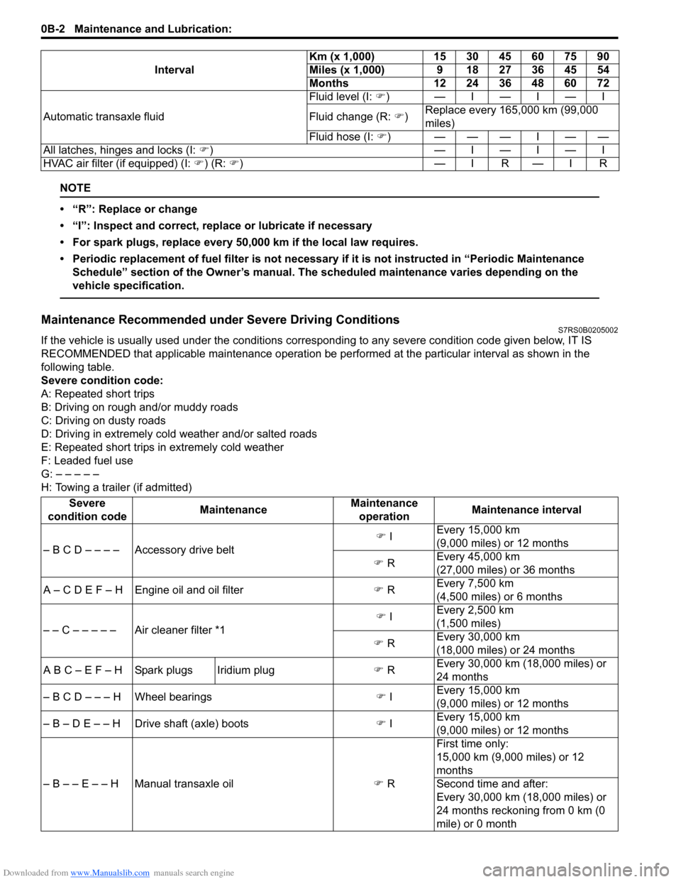
Maintenance Recommended under Severe Driving ConditionsS7RS0B0205002
If the vehicle is usually used under the conditions corres ponding to any severe condition code given below, IT IS
RECOMMENDED that applicable maintenance operation be per formed at the particular interval as shown in the
following table.
Severe condition code:
A: Repeated short trips
B: Driving on rough and/or muddy roads
C: Driving on dusty roads
D: Driving in extremely cold weather and/or salted roads
E: Repeated short trips in extremely cold weather
F: Leaded fuel use
G: – – – – –
H: Towing a trailer (if admitted) Automatic transaxle fluid
Fluid level (I:
�)) —I—I—I
Fluid change (R: �)) Replace every 165,000 km (99,000
miles)
Fluid hose (I: �))———I——
All latches, hinges and locks (I: �)) —I—I—I
HVAC air filter (if equipped) (I: �) ) (R: �))— IR — IR
Interval
Km (x 1,000)
15 30 45 60 75 90
Miles (x 1,000) 9 18 27 36 45 54
Months 12 24 36 48 60 72
Severe
condition code MaintenanceMaintenance
operation Maintenance interval
– B C D – – – – Accessory drive belt �)
I Every 15,000 km
(9,000 miles) or 12 months
�) R Every 45,000 km
(27,000 miles) or 36 months
A – C D E F – H Engine oil and oil filter �) R Every 7,500 km
(4,500 miles) or 6 months
– – C – – – – – Air cleaner filter *1 �)
I Every 2,500 km
(1,500 miles)
�) R Every 30,000 km
(18,000 miles) or 24 months
A B C – E F – H Spark plugs Iridium plug �) R Every 30,000 km (18,000 miles) or
24 months
– B C D – – – H Wheel bearings �) I Every 15,000 km
(9,000 miles) or 12 months
– B – D E – – H Drive shaft (axle) boots �) I Every 15,000 km
(9,000 miles) or 12 months
– B – – E – – H Manual transaxle oil �) R First time only:
15,000 km (9,000 miles) or 12
months
Second time and after:
Every 30,000 km (18,000 miles) or
24 months reckoning from 0 km (0
mile) or 0 month
Page 442 of 1496

Downloaded from www.Manualslib.com manuals search engine 2B-9 Front Suspension:
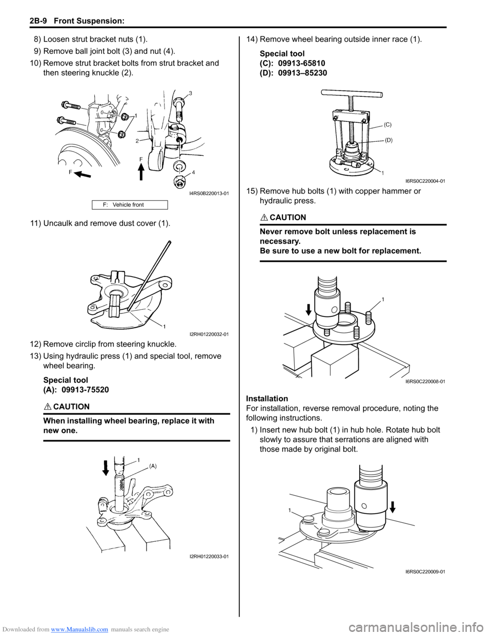
8) Loosen strut bracket nuts (1).
9) Remove ball joint bolt (3) and nut (4).
10) Remove strut bracket bolt s from strut bracket and
then steering knuckle (2).
11) Uncaulk and remove dust cover (1).
12) Remove circlip from steering knuckle.
13) Using hydraulic press (1) and special tool, remove wheel bearing.
Special tool
(A): 09913-75520
CAUTION!
When installing wheel bearing, replace it with
new one.
14) Remove wheel bearing outside inner race (1).
Special tool
(C): 09913-65810
(D): 09913–85230
15) Remove hub bolts (1) with copper hammer or hydraulic press.
CAUTION!
Never remove bolt unle ss replacement is
necessary.
Be sure to use a new bolt for replacement.
Installation
For installation, reverse removal procedure, noting the
following instructions.
1) Insert new hub bolt (1) in hub hole. Rotate hub bolt slowly to assure that serrations are aligned with
those made by original bolt.
F: Vehicle front
I4RS0B220013-01
I2RH01220032-01
I2RH01220033-01
I6RS0C220004-01
1
I6RS0C220008-01
1
I6RS0C220009-01
Page 469 of 1496

Downloaded from www.Manualslib.com manuals search engine Wheels and Tires: 2D-2
Lower than recommended pressure can cause:
• Tire squeal on turns
• Hard Steering
• Rapid and uneven wear on the edges of the tread
• Tire rim bruises and rupture
• Tire cord breakage
• High tire temperature
• Reduced handling
• High fuel consumption
Replacement Tires
When replacement is necessary, the original equipment
type tire should be used. Refer to the Tire Placard.
Replacement tires should be of the same size, load
range and construction as those originally on the vehicle.
Use of any other size or type tire may affect ride,
handling, speedometer / odometer calibration, vehicle
ground clearance and tire or snow chain clearance to the
body and chassis.
It is recommended that new tires be installed in pairs on
the same axle. If necessary to replace only one tire, it
should be paired with the tire having the most tread, to
equalize braking traction.
WARNING!
Do not mix different types of tires on the
same vehicle such as radial, bias and bias-
belted tires except in emergencies, because
handling may be seriously affected and may
result in loss of control.
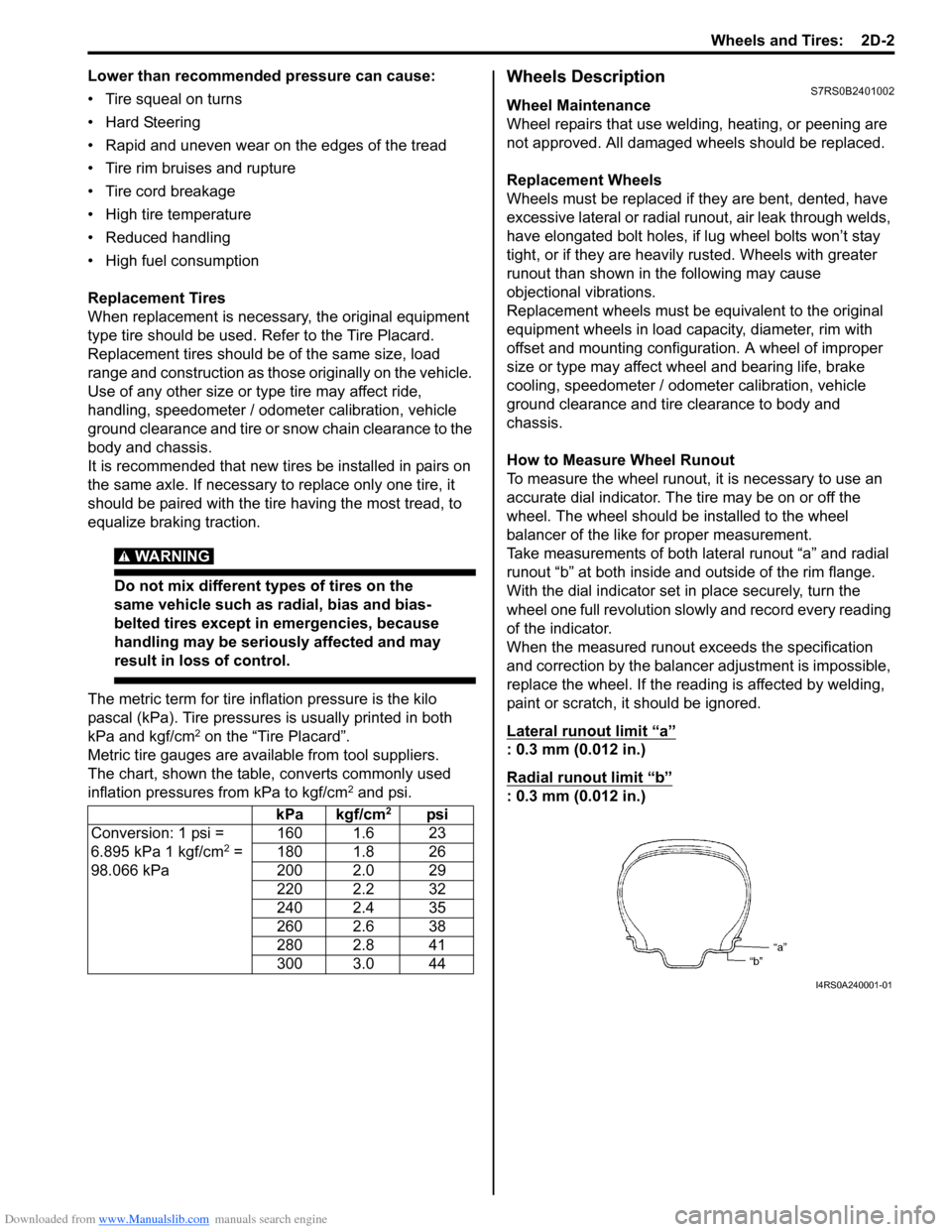
The metric term for tire infl ation pressure is the kilo
pascal (kPa). Tire pressures is usually printed in both
kPa and kgf/cm
2 on the “Tire Placard”.
Metric tire gauges are available from tool suppliers.
The chart, shown the table, converts commonly used
inflation pressures from kPa to kgf/cm
2 and psi.
Wheels DescriptionS7RS0B2401002
Wheel Maintenance
Wheel repairs that use welding, heating, or peening are
not approved. All damaged wheels should be replaced.
Replacement Wheels
Wheels must be replaced if they are bent, dented, have
excessive lateral or radial runout, air leak through welds,
have elongated bolt holes, if lug wheel bolts won’t stay
tight, or if they are heavily rusted. Wheels with greater
runout than shown in the following may cause
objectional vibrations.
Replacement wheels must be equivalent to the original
equipment wheels in load capacity, diameter, rim with
offset and mounting configuration. A wheel of improper
size or type may affect wheel and bearing life, brake
cooling, speedometer / odometer calibration, vehicle
ground clearance and tire clearance to body and
chassis.
How to Measure Wheel Runout
To measure the wheel runout, it is necessary to use an
accurate dial indicator. The tire may be on or off the
wheel. The wheel should be installed to the wheel
balancer of the like for proper measurement.
Take measurements of both lateral runout “a” and radial
runout “b” at both inside an d outside of the rim flange.
With the dial indicator set in place securely, turn the
wheel one full revolution slowly and record every reading
of the indicator.
When the measured runout exceeds the specification
and correction by the balancer adjustment is impossible,
replace the wheel. If the reading is affected by welding,
paint or scratch, it should be ignored.
Lateral runout limit “a”
: 0.3 mm (0.012 in.)
Radial runout limit “b”
: 0.3 mm (0.012 in.)
kPa kgf/cm2psi
Conversion: 1 psi =
6.895 kPa 1 kgf/cm
2 =
98.066 kPa 160 1.6 23
180 1.8 26
200 2.0 29
220 2.2 32
240 2.4 35
260 2.6 38
280 2.8 41
300 3.0 44
I4RS0A240001-01