C37 SUZUKI SWIFT 2007 2.G Service Owners Manual
[x] Cancel search | Manufacturer: SUZUKI, Model Year: 2007, Model line: SWIFT, Model: SUZUKI SWIFT 2007 2.GPages: 1496, PDF Size: 34.44 MB
Page 247 of 1496
Downloaded from www.Manualslib.com manuals search engine Engine General Information and Diagnosis: 1A-197
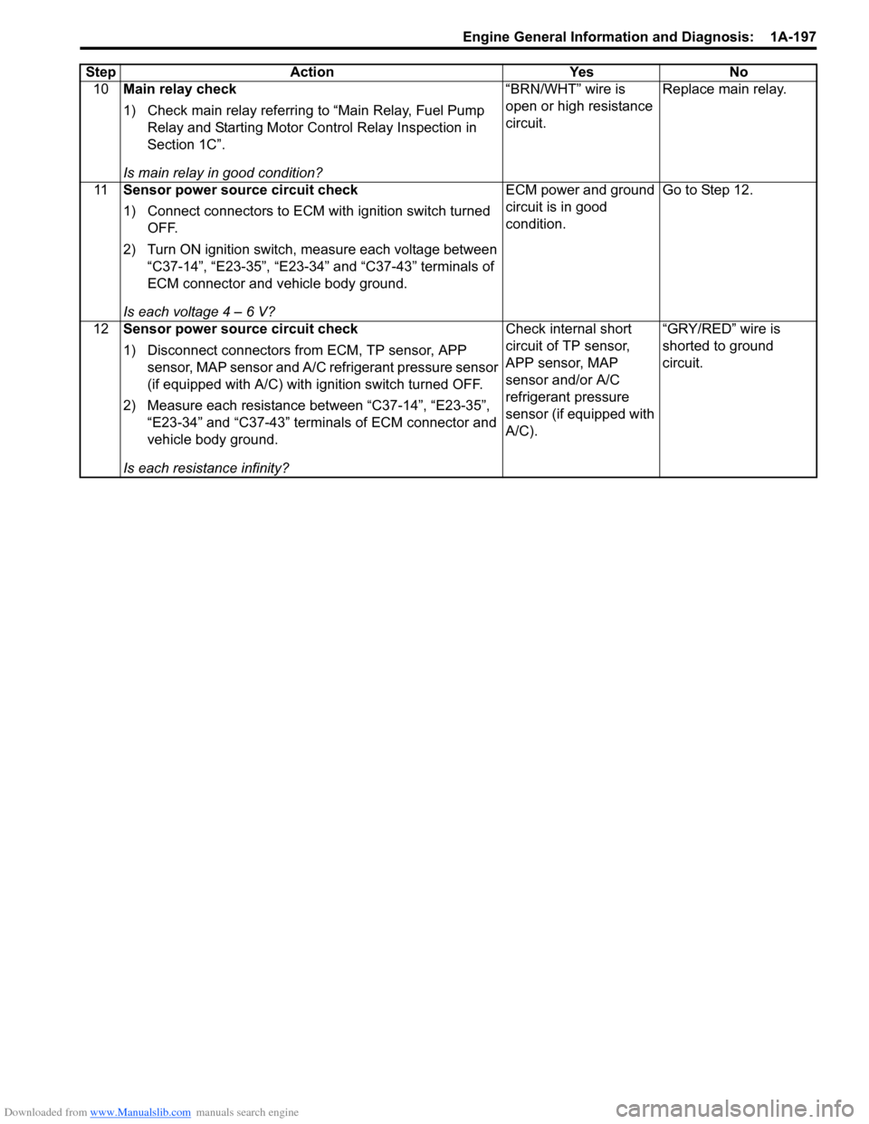
10Main relay check
1) Check main relay referring to “Main Relay, Fuel Pump
Relay and Starting Motor Control Relay Inspection in
Section 1C”.
Is main relay in good condition? “BRN/WHT” wire is
open or high resistance
circuit.
Replace main relay.
11 Sensor power source circuit check
1) Connect connectors to ECM with ignition switch turned
OFF.
2) Turn ON ignition switch, measure each voltage between “C37-14”, “E23-35”, “E23-34” and “C37-43” terminals of
ECM connector and vehicle body ground.
Is each voltage 4 – 6 V? ECM power and ground
circuit is in good
condition.
Go to Step 12.
12 Sensor power source circuit check
1) Disconnect connectors from ECM, TP sensor, APP
sensor, MAP sensor and A/C refrigerant pressure sensor
(if equipped with A/C) with i gnition switch turned OFF.
2) Measure each resistance between “C37-14”, “E23-35”, “E23-34” and “C37-43” terminals of ECM connector and
vehicle body ground.
Is each resistance infinity? Check internal short
circuit of TP sensor,
APP sensor, MAP
sensor and/or A/C
refrigerant pressure
sensor (if equipped with
A/C).
“GRY/RED” wire is
shorted to ground
circuit.
Step Action Yes No
Page 248 of 1496
Downloaded from www.Manualslib.com manuals search engine 1A-198 Engine General Information and Diagnosis:
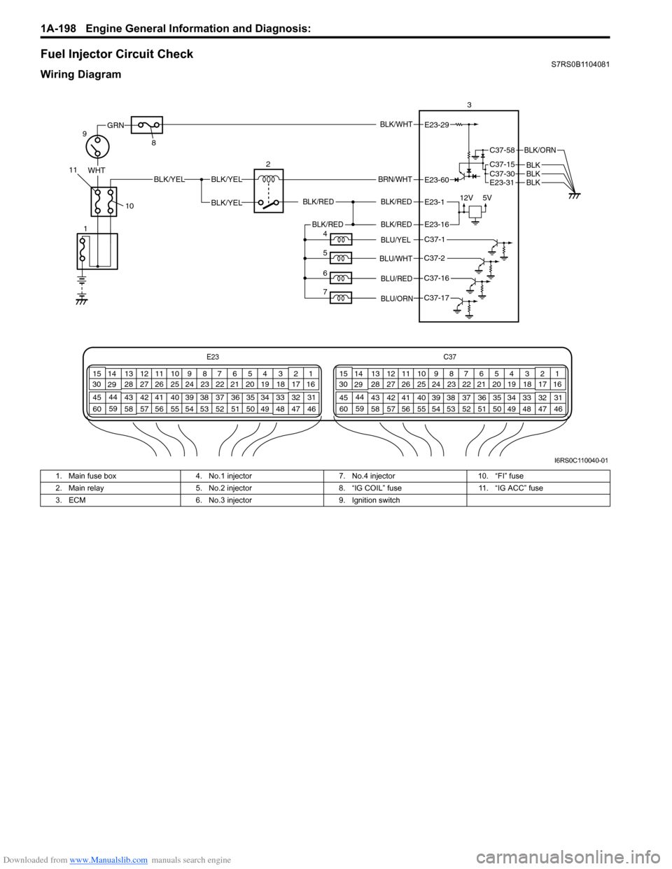
Fuel Injector Circuit CheckS7RS0B1104081
Wiring Diagram
BLK/WHTBLK/RED
BLK/RED
WHTBLK/YELBLK/YEL
BLK/YEL
GRN
BRN/WHT
12V 5V
9
2
8 3E23-29
E23-1
E23-60
10
11
E23
C37
34
1819
567
1011
17
20
47 46
495051
2122
52 16
25 9
24
14
29
55
57 54 53
59
60 58 2
262728
15
30
56 4832 31
34353637
40
42 39 38
44
45 43 41 331
1213
238
34
1819
567
1011
17
20
47 46
495051
2122
52 16
25 9
24
14
29
55
57 54 53
59
60 58 2
262728
15
30
56 4832 31
34353637
40
42 39 38
44
45 43 41 331
1213
238
C37-1
C37-2
C37-16
C37-17
BLK/REDBLK/RED
BLU/YEL
BLU/RED
BLU/ORN
BLU/WHT
E23-16
4
5
6
71
C37-58
C37-15 C37-30 E23-31
BLK/ORN
BLKBLKBLK
I6RS0C110040-01
1. Main fuse box 4. No.1 injector 7. No.4 injector10. “FI” fuse
2. Main relay 5. No.2 injector 8. “IG COIL” fuse 11. “IG ACC” fuse
3. ECM 6. No.3 injector 9. Ignition switch
Page 249 of 1496
Downloaded from www.Manualslib.com manuals search engine Engine General Information and Diagnosis: 1A-199
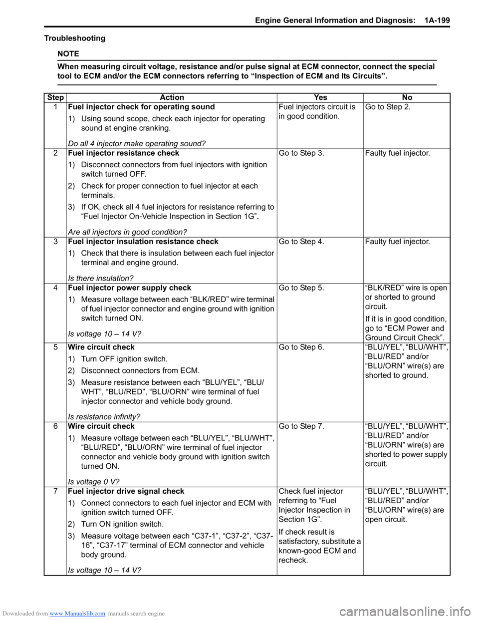
Troubleshooting
NOTE
When measuring circuit voltage, resistance and/or pulse signal at ECM connector, connect the special
tool to ECM and/or the ECM connectors referri ng to “Inspection of ECM and Its Circuits”.
StepAction YesNo
1 Fuel injector check for operating sound
1) Using sound scope, check each injector for operating
sound at engine cranking.
Do all 4 injector ma ke operating sound? Fuel injectors circuit is
in good condition.
Go to Step 2.
2 Fuel injector resistance check
1) Disconnect connectors from fuel injectors with ignition
switch turned OFF.
2) Check for proper connection to fuel injector at each terminals.
3) If OK, check all 4 fuel inject ors for resistance referring to
“Fuel Injector On-Vehicle Inspection in Section 1G”.
Are all injectors in good condition? Go to Step 3.
Faulty fuel injector.
3 Fuel injector insulation resistance check
1) Check that there is insulation between each fuel injector
terminal and engine ground.
Is there insulation? Go to Step 4.
Faulty fuel injector.
4 Fuel injector power supply check
1) Measure voltage between each “BLK/RED” wire terminal
of fuel injector connector and engine ground with ignition
switch turned ON.
Is voltage 10 – 14 V? Go to Step 5.
“BLK/RED” wire is open
or shorted to ground
circuit.
If it is in good condition,
go to “ECM Power and
Ground Circuit Check”.
5 Wire circuit check
1) Turn OFF ignition switch.
2) Disconnect connectors from ECM.
3) Measure resistance between each “BLU/YEL”, “BLU/
WHT”, “BLU/RED”, “BLU/ORN” wire terminal of fuel
injector connector and vehicle body ground.
Is resistance infinity? Go to Step 6.
“BLU/YEL”, “BLU/WHT”,
“BLU/RED” and/or
“BLU/ORN” wire(s) are
shorted to ground.
6 Wire circuit check
1) Measure voltage between each “BLU/YEL”, “BLU/WHT”,
“BLU/RED”, “BLU/ORN” wire terminal of fuel injector
connector and vehicle body ground with ignition switch
turned ON.
Is voltage 0 V? Go to Step 7.
“BLU/YEL”, “BLU/WHT”,
“BLU/RED” and/or
“BLU/ORN” wire(s) are
shorted to power supply
circuit.
7 Fuel injector drive signal check
1) Connect connectors to each fuel injector and ECM with
ignition switch turned OFF.
2) Turn ON ignition switch.
3) Measure voltage between each “C37-1”, “C37-2”, “C37- 16”, “C37-17” terminal of ECM connector and vehicle
body ground.
Is voltage 10 – 14 V? Check fuel injector
referring to “Fuel
Injector Inspection in
Section 1G”.
If check result is
satisfactory, substitute a
known-good ECM and
recheck.
“BLU/YEL”, “BLU/WHT”,
“BLU/RED” and/or
“BLU/ORN” wire(s) are
open circuit.
Page 250 of 1496
Downloaded from www.Manualslib.com manuals search engine 1A-200 Engine General Information and Diagnosis:
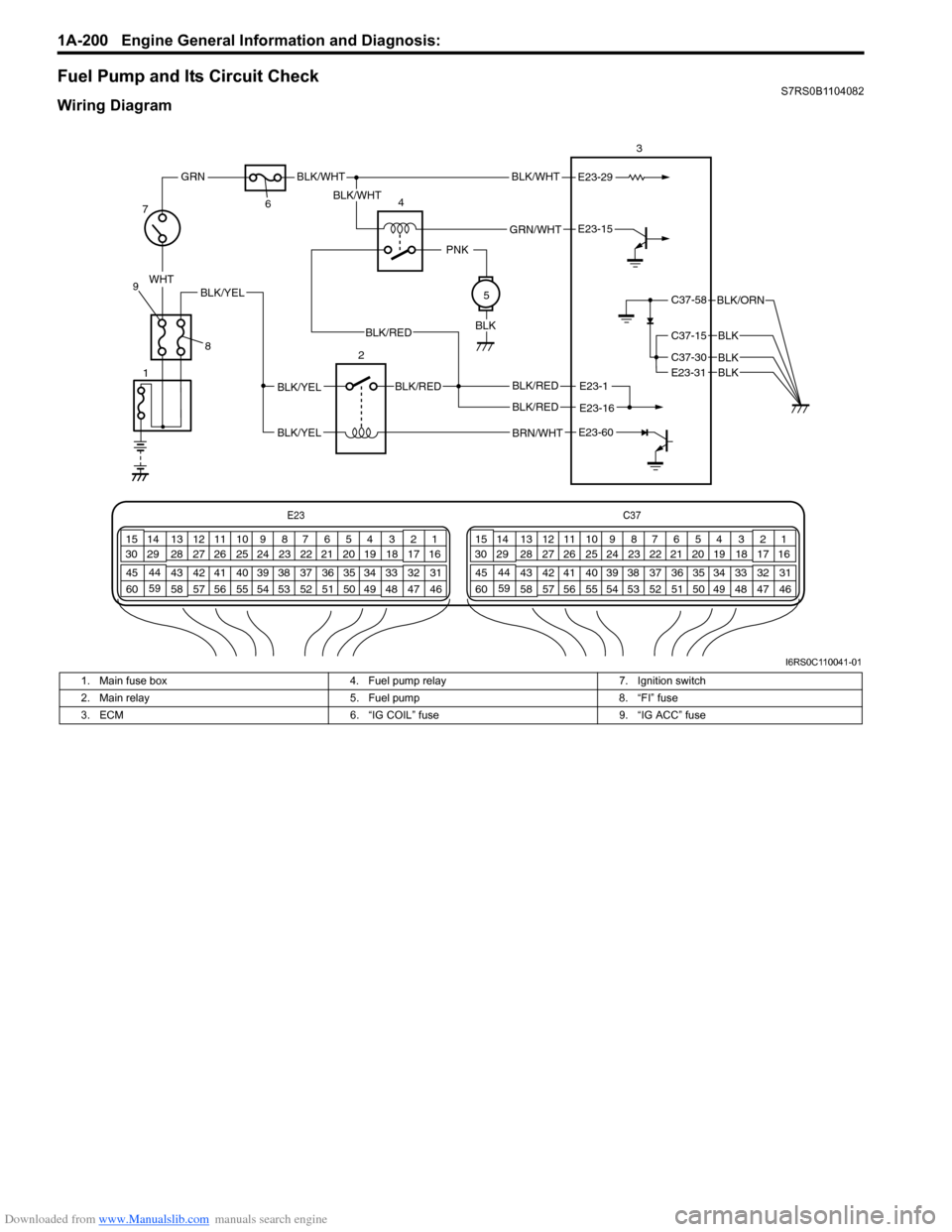
Fuel Pump and Its Circuit CheckS7RS0B1104082
Wiring Diagram
E23-1
E23-60
E23-15
BRN/WHT
BLK/REDBLK/YEL
BLK/YEL
BLK/RED
E23-29BLK/WHT
GRN/WHT
BLK/WHT
BLK/WHT
PNK
BLK
WHT
GRN
C37-58
C37-15
C37-30
BLK/ORN
BLK
BLKE23-31BLK
78
9 6
4 3
2 5
E23
C37
34
1819
567
1011
17
20
47 46
495051
2122
52 16
25 9
24
14
29
55
57 54 53
59
60 58 2
262728
15
30
56 48 32 31
34353637
40
42 39 38
44
45 43 41 331
1213
238
34
1819
567
1011
17
20
47 46
495051
2122
52 16
25 9
24
14
29
55
57 54 53
59
60 58 2
262728
15
30
56 4832 31
34353637
40
42 39 38
44
45 43 41 331
1213
238
BLK/YEL
1
E23-16BLK/RED
BLK/RED
I6RS0C110041-01
1. Main fuse box 4. Fuel pump relay 7. Ignition switch
2. Main relay 5. Fuel pump 8. “FI” fuse
3. ECM 6. “IG COIL” fuse 9. “IG ACC” fuse
Page 255 of 1496
Downloaded from www.Manualslib.com manuals search engine Engine General Information and Diagnosis: 1A-205
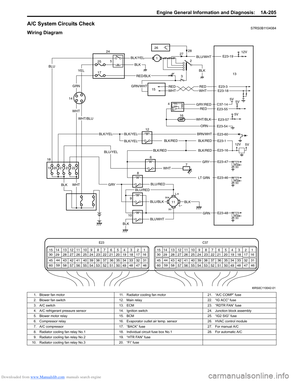
A/C System Circuits CheckS7RS0B1104084
Wiring Diagram
E23C37
34
1819
567
1011
17
20
47 46
495051
2122
52 16
25 9
24
14
29
55
57 54 53
59
60 58 2
262728
15
30
56 4832 31
34353637
40
42 39 38
44
45 43 41 331
1213
238
34
1819
567
1011
17
20
47 46
495051
2122
52 16
25 9
24
14
29
55
57 54 53
59
60 58 2
262728
15
30
56 4832 31
34353637
40
42 39 38
44
45 43 41 331
1213
238
BLK/REDBLK/RED
BLK/YELBLK/YEL
BLK/YEL
BRN/WHT
12V
5V
12
E23-1
E23-60
BLK/RED
LT GRN
BLK/REDE23-16
E23-46
L+
L–
H–
H
+
BLU/RED
BLK
BLUWHTBLK
BLU/BLK
BLU/RED
GRN
GRY
E23-48
8
11
2
3BLU/WHT
REDWHTREDWHTE23-3E23-18
E23-19
6
BLK
WHT
BLK 12V
E23-47 GRY
WHT
YELBLU
WHT
BLK/YEL
RED/BLK
GRN/WHT
WHT/BLU1
713
14
5V
5V
4
E23-55C37-14GRY/REDRED
E23-54ORN 5V
E23-57WHT/BLK16
9
10
25
17
5
24
15
22
BLU/YEL
23212019
GRN
BLK
18
26
28
27
I6RS0C110042-01
1. Blower fan motor 11. Radiator cooling fan motor 21. “A/C COMP” fuse
2. Blower fan switch 12. Main relay 22. “IG ACC” fuse
3. A/C switch 13. ECM 23. “RDTR FAN” fuse
4. A/C refrigerant pressure sensor 14. Ignition switch 24. Junction block assembly
5. Blower motor relay 15. BCM 25. “IG2 SIG” fuse
6. Compressor relay 16. Evaporator outlet air temp. sensor 26. HVAC control module
7. A/C compressor 17. “BACK” fuse 27. For manual A/C
8. Radiator cooling fan relay No.1 18. Individual circuit fuse box No.1 28. For automatic A/C
9. Radiator cooling fan relay No.2 19. “HTR FAN” fuse
10. Radiator cooling fan relay No.3 20. “FI” fuse
Page 259 of 1496
Downloaded from www.Manualslib.com manuals search engine Engine General Information and Diagnosis: 1A-209
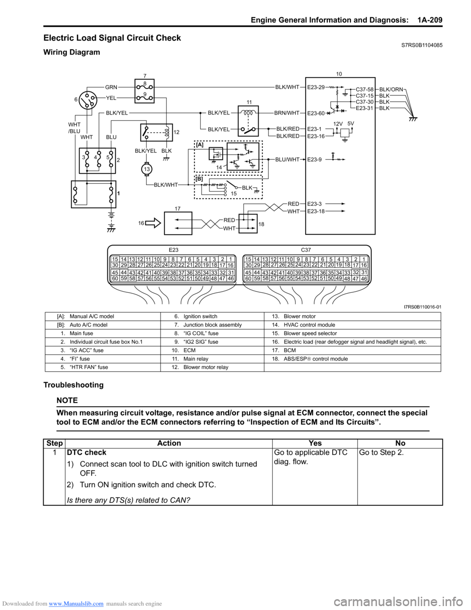
Electric Load Signal Circuit CheckS7RS0B1104085
Wiring Diagram
Troubleshooting
NOTE
When measuring circuit voltage, resistance and/or pulse signal at ECM connector, connect the special
tool to ECM and/or the ECM connectors referri ng to “Inspection of ECM and Its Circuits”.
BLK/WHT
BLK/RED
WHT
BRN/WHT
12V5V
11
BLK/YELBLK/YEL
BLK/YEL
BLKBLKBLK
BLK/ORN
10
18
17
BLU/WHT
15
WHTRED
43
YEL
5
13
BLK/WHT
BLKBLK/YEL
GRN
WHT
/BLU
BLU
16
2
6
7
12
8
9
BLK
WHT
RED
E23-29
E23-60
E23-1E23-16
E23-9
E23-3E23-18
C37-58C37-15
E23-31C37-30
BLK/RED
[A]
[B]
E23 C37
34
1819
567
10
11
17
20
47 46
495051
2122
52 16
25 9
24
14
29
5557 54 53
59
60 58 2
262728
15
30
56 4832 31
34353637
4042 39 38
44
45 43 41 331
1213
238
34
1819
567
10
11
17
20
47 46
495051
2122
52 16
25 9
24
14
29
5557 54 53
59
60 58 2
262728
15
30
56 4832 31
34353637
4042 39 38
44
45 43 41 331
12
13
238
1
14
I7RS0B110016-01
[A]: Manual A/C model
6. Ignition switch13. Blower motor
[B]: Auto A/C model 7. Junction block assembly14. HVAC control module
1. Main fuse 8. “IG COIL” fuse15. Blower speed selector
2. Individual circuit fuse box No.1 9. “IG2 SIG” fuse16. Electric load (rear defogger signal and headlight signal), etc.
3. “IG ACC” fuse 10. ECM17. BCM
4. “FI” fuse 11. Main relay18. ABS/ESP® control module
5. “HTR FAN” fuse 12. Blower motor relay
StepAction YesNo
1 DTC check
1) Connect scan tool to DLC with ignition switch turned
OFF.
2) Turn ON ignition switch and check DTC.
Is there any DTS(s) related to CAN? Go to applicable DTC
diag. flow.
Go to Step 2.
Page 261 of 1496
Downloaded from www.Manualslib.com manuals search engine Engine General Information and Diagnosis: 1A-211
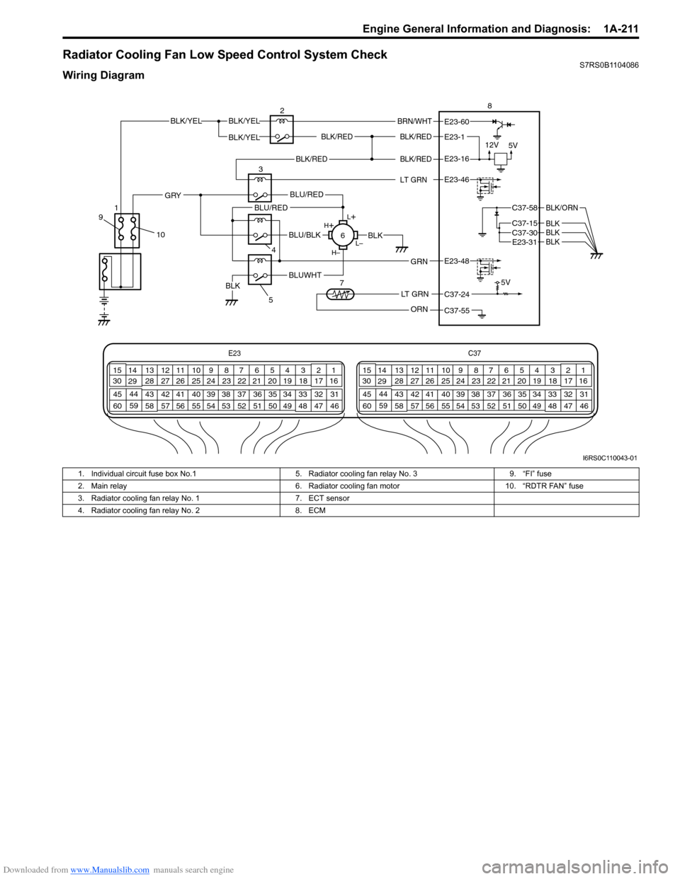
Radiator Cooling Fan Low Speed Control System CheckS7RS0B1104086
Wiring Diagram
E23C37
34
1819
567
1011
17
20
47 46
495051
2122
52 16
25 9
24
14
29
55
57 54 53
59
60 58 2
262728
15
30
56 4832 31
34353637
40
42 39 38
44
45 43 41 331
1213
238
34
1819
567
1011
17
20
47 46
495051
2122
52 16
25 9
24
14
29
55
57 54 53
59
60 58 2
262728
15
30
56 4832 31
34353637
40
42 39 38
44
45 43 41 331
1213
238
BLK/REDBLK/RED
BLK/YELBLK/YEL
BLK/YEL
BRN/WHT
12V
5V5V
2
8
E23-1
E23-60
C37-58
C37-15 C37-30
BLK/ORN
BLKBLKE23-31 BLK
BLK/RED
LT GRN
BLK/REDE23-16
E23-46
L+
L–
H–
H
+
BLU/RED
BLK
BLUWHTBLK
BLU/BLK
BLU/RED
4
GRN
GRY
E23-48
LT GRN
ORN
C37-24
C37-55
35
6
7
10
9
1
I6RS0C110043-01
1. Individual circuit fuse box No.1
5. Radiator cooling fan relay No. 3 9. “FI” fuse
2. Main relay 6. Radiator cooling fan motor10. “RDTR FAN” fuse
3. Radiator cooling fan relay No. 1 7. ECT sensor
4. Radiator cooling fan relay No. 2 8. ECM
Page 263 of 1496
Downloaded from www.Manualslib.com manuals search engine Engine General Information and Diagnosis: 1A-213
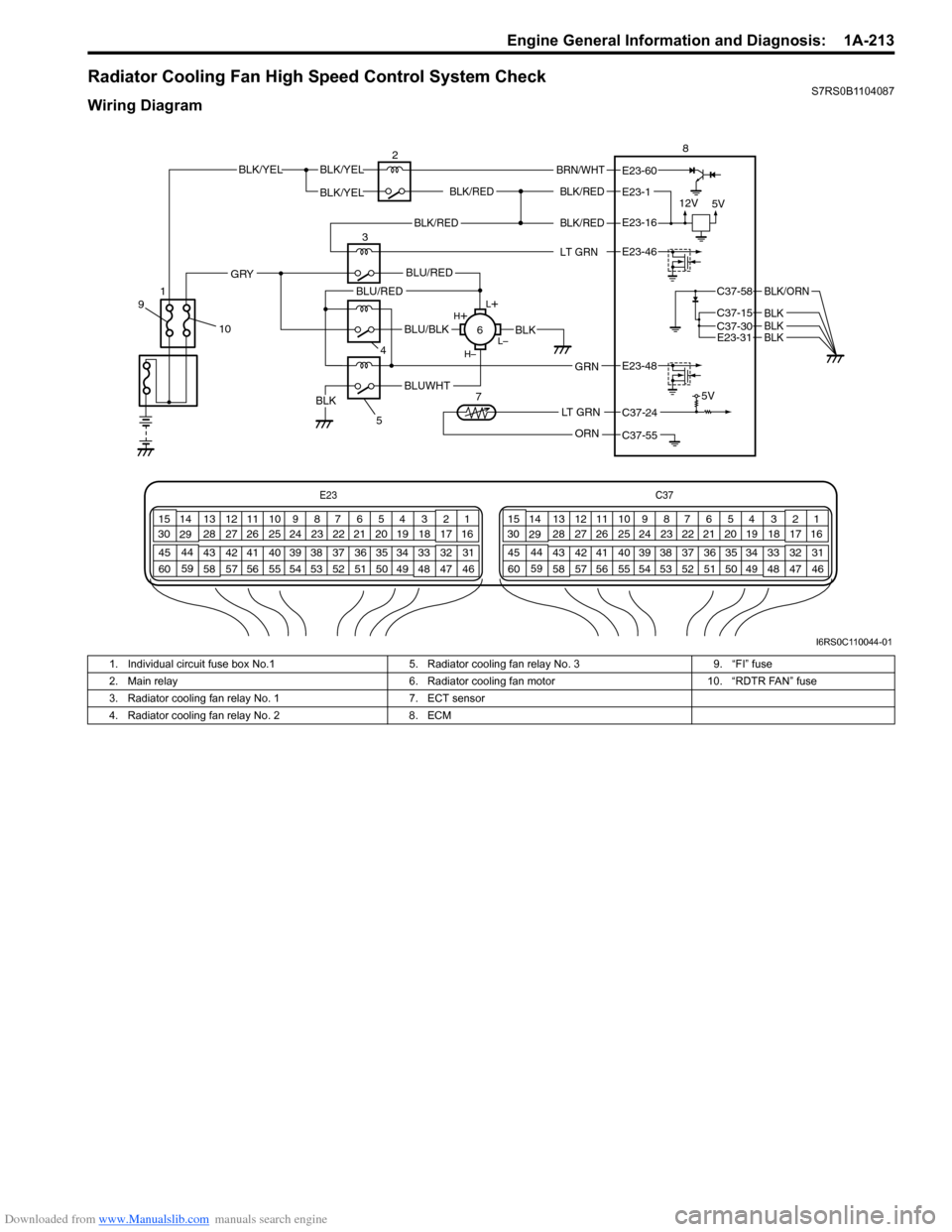
Radiator Cooling Fan High Speed Control System CheckS7RS0B1104087
Wiring Diagram
E23C37
34
1819
567
1011
17
20
47 46
495051
2122
52 16
25 9
24
14
29
55
57 54 53
59
60 58 2
262728
15
30
56 4832 31
34353637
40
42 39 38
44
45 43 41 331
1213
238
34
1819
567
1011
17
20
47 46
495051
2122
52 16
25 9
24
14
29
55
57 54 53
59
60 58 2
262728
15
30
56 4832 31
34353637
40
42 39 38
44
45 43 41 331
1213
238
BLK/REDBLK/RED
BLK/YELBLK/YEL
BLK/YEL
BRN/WHT
12V
5V5V
2
8
E23-1
E23-60
C37-58
C37-15 C37-30
BLK/ORN
BLKBLKE23-31 BLK
BLK/RED
LT GRN
BLK/REDE23-16
E23-46
L+
L–
H–
H
+
BLU/RED
BLK
BLUWHTBLK
BLU/BLK
BLU/RED
4
GRN
GRY
E23-48
LT GRN
ORN
C37-24
C37-55
35
6
7
10
9
1
I6RS0C110044-01
1. Individual circuit fuse box No.1
5. Radiator cooling fan relay No. 3 9. “FI” fuse
2. Main relay 6. Radiator cooling fan motor10. “RDTR FAN” fuse
3. Radiator cooling fan relay No. 1 7. ECT sensor
4. Radiator cooling fan relay No. 2 8. ECM
Page 269 of 1496
Downloaded from www.Manualslib.com manuals search engine Aux. Emission Control Devices: 1B-2
EVAP Canister Purge Valve and Its Circuit
Inspection
S7RS0B1206002
WARNING!
Do not apply vacuum by mouth; otherwise
harmful fuel vapor can be breathed in.
CAUTION!
Do not apply vacuum more than –86 kPa (–
12.47 psi); otherwise EVAP canister purge
valve could be damaged.
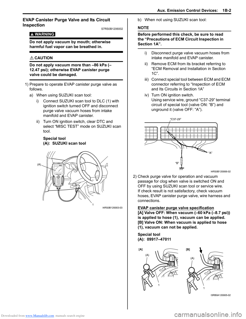
1) Prepare to operate EVAP canister purge valve as follows.
a) When using SUZUKI scan tool:
i) Connect SUZUKI scan tool to DLC (1) with ignition switch turned OFF and disconnect
purge valve vacuum hoses from intake
manifold and EVAP canister.
ii) Turn ON ignition switch, clear DTC and select “MISC TEST” mode on SUZUKI scan
tool.
Special tool
(A): SUZUKI scan tool b) When not using SUZUKI scan tool:
NOTE
Before performed this check, be sure to read
the “Precautions of ECM Circuit Inspection in
Section 1A”.
i) Disconnect purge valve vacuum hoses from
intake manifold and EVAP canister.
ii) Remove ECM from it s bracket referring to
“ECM Removal and Inst allation in Section
1C”.
iii) Connect special tool between ECM and ECM connector referring to “Inspection of ECM
and Its Circuits in Section 1A”
iv) Turn ON ignition switch. Using service wire, ground “C37-29” terminal
circuit of special tool (valve ON: “B”) and
unground it (valve OFF: “A”).
2) Check purge valve for operation and vacuum passage for clog when valve is switched ON and
OFF by using SUZUKI scan tool or service wire.
If check result is not satisfactory, check vacuum
hoses, EVAP canister purge valve, wire harness and
connections.
EVAP canister purge valve specification
[A] Valve OFF: When vacuum (–60 kPa (–8.7 psi))
is applied to hose (1), vacuum can be applied.
[B] Valve ON: When vacuum is applied to hose
(1), vacuum can not be applied.
Special tool
(A): 09917–47011
(A)
1
I4RS0B120003-03
“C37-29”“A”
“B”
I4RS0B120006-02
[A] [B]
1
(A)1
(A)
I3RB0A120005-02
Page 283 of 1496
Downloaded from www.Manualslib.com manuals search engine Engine Electrical Devices: 1C-11
MAF and IAT Sensor On-Vehicle InspectionS7RS0B1306018
NOTE
Before performed this inspection, be sure to
read the “Precautions of ECM Circuit
Inspection in Section 1A”.
1) Disconnect negative (–) cable at battery.
2) Disconnect MAF and IAT sensor connector.
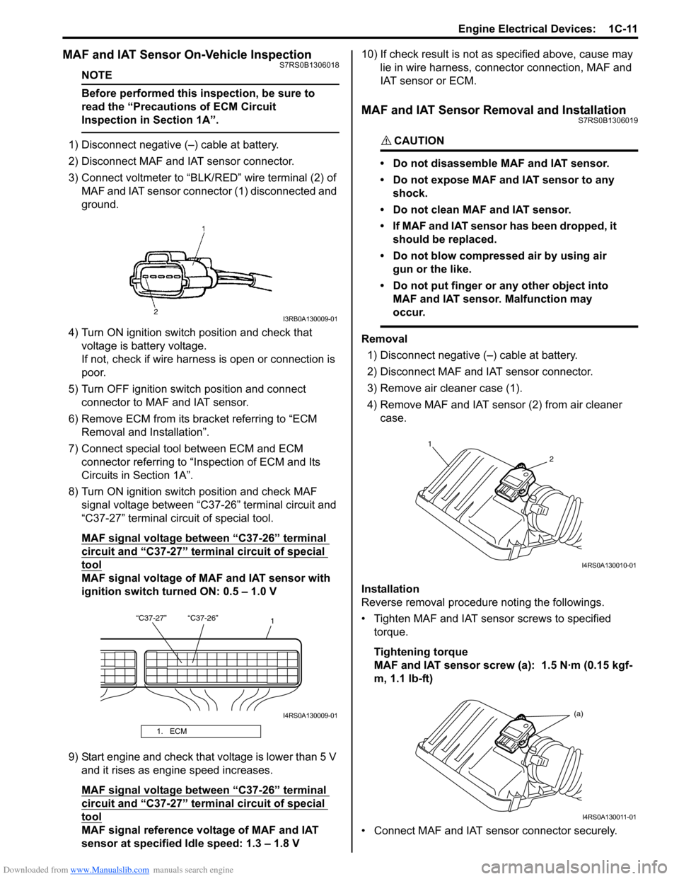
3) Connect voltmeter to “BLK/RED” wire terminal (2) of
MAF and IAT sensor connector (1) disconnected and
ground.
4) Turn ON ignition switch position and check that voltage is battery voltage.
If not, check if wire harness is open or connection is
poor.
5) Turn OFF ignition switch position and connect connector to MAF and IAT sensor.
6) Remove ECM from its bracket referring to “ECM Removal and Installation”.
7) Connect special tool between ECM and ECM connector referring to “Inspection of ECM and Its
Circuits in Section 1A”.
8) Turn ON ignition switch position and check MAF signal voltage between “C37-26” terminal circuit and
“C37-27” terminal circuit of special tool.
MAF signal voltage between “C37-26” terminal
circuit and “C37-27” termi nal circuit of special
tool
MAF signal voltage of MAF and IAT sensor with
ignition switch turned ON: 0.5 – 1.0 V
9) Start engine and check that voltage is lower than 5 V and it rises as engine speed increases.
MAF signal voltage between “C37-26” terminal
circuit and “C37-27” termi nal circuit of special
tool
MAF signal reference voltage of MAF and IAT
sensor at specified Idle speed: 1.3 – 1.8 V 10) If check result is not as
specified above, cause may
lie in wire harness, connec tor connection, MAF and
IAT sensor or ECM.
MAF and IAT Sensor Removal and InstallationS7RS0B1306019
CAUTION!
• Do not disassemble MAF and IAT sensor.
• Do not expose MAF and IAT sensor to any shock.
• Do not clean MAF and IAT sensor.
• If MAF and IAT sensor has been dropped, it should be replaced.
• Do not blow compressed air by using air gun or the like.
• Do not put finger or any other object into MAF and IAT sensor. Malfunction may
occur.
Removal
1) Disconnect negative (–) cable at battery.
2) Disconnect MAF and IAT sensor connector.
3) Remove air cleaner case (1).
4) Remove MAF and IAT sensor (2) from air cleaner case.
Installation
Reverse removal procedure noting the followings.
• Tighten MAF and IAT sensor screws to specified torque.
Tightening torque
MAF and IAT sensor screw (a): 1.5 N·m (0.15 kgf-
m, 1.1 lb-ft)
• Connect MAF and IAT sensor connector securely.
1. ECM
I3RB0A130009-01
“C37-27” “C37-26” 1
I4RS0A130009-01
1
2
I4RS0A130010-01
(a)
I4RS0A130011-01