C37 SUZUKI SWIFT 2007 2.G Service Workshop Manual
[x] Cancel search | Manufacturer: SUZUKI, Model Year: 2007, Model line: SWIFT, Model: SUZUKI SWIFT 2007 2.GPages: 1496, PDF Size: 34.44 MB
Page 1424 of 1496

Downloaded from www.Manualslib.com manuals search engine 10B-21 Body Electrical Control System:
DTC B1170 (No. 1170): EEPROM Access ErrorS7RS0BA204012
DTC Detecting Condition and Possible Cause
DTC Troubleshooting
NOTE
Before performing steps below, be sure to perform “Body Electrical Control System Check”.
1) Ignition switch OFF.
2) Replace BCM.
3) Repeat BCM Check Flow Table.
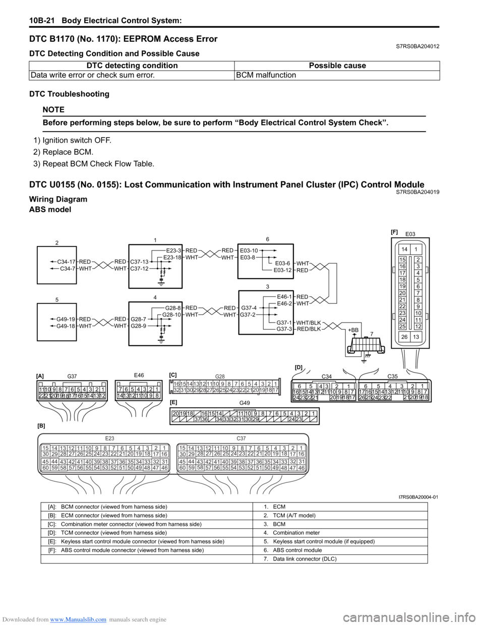
DTC U0155 (No. 0155): Lost Communication with Instrument Panel Cluster (IPC) Control ModuleS7RS0BA204019
Wiring Diagram
ABS model DTC detecting condition Possible cause
Data write error or check sum error. BCM malfunction
REDWHTE03-6E03-12
6
3
7
REDWHT
1
[B]
[A]
G37E46
1234567
1234567
8910
11
8910
11
121314 121314
151617
18
19202122 [D]65
1615 141312 11 43
2423 2122 10 9 8 7
21
1920 1817
C3417 16
26 2515 14
65 3
42
13 12
23 2224 1110 9
212019 87
18
1
C35
[E]
REDWHTC37-13C37-12REDWHTC34-17C34-7
2
12345678910
11
141516
36 34 33 32 31 30 29 24 23
37
181920
[C] [F]
G49
E23-3E23-18
4
REDWHTG28-7G28-9REDWHTG49-19G49-18
5
REDWHTE03-10E03-8
G37-4G37-2
REDWHTE46-1E46-2REDWHTREDWHTG28-8G28-10
E03
15
16
17
18
19
20
21
22
23
24
25 2
3
4
5
6
7
8
9
10
11
12
1
13
14
26
E23C37
34
1819
567
1011
17
20
47 46
495051
2122
52 16
25 9
24
14
29
5557 54 53
59
60 58 2
262728
15
30
56 4832 31
34353637
4042 39 38
44
45 43 41 33 1
1213
238
34
1819
567
1011
17
20
47 46
495051
2122
52 16
25 9
24
14
29
5557 54 53
59
60 58 2
262728
15
30
56 4832 31
34353637
4042 39 38
44
45 43 41 331
1213
238
G281234567
8
910111213141516
1718
19
20
212223242526272829303132
RED/BLKWHT/BLKG37-3G37-1+BB
I7RS0BA20004-01
[A]: BCM connector (viewed from harness side) 1. ECM
[B]: ECM connector (viewed from harness side) 2. TCM (A/T model)
[C]: Combination meter connector (viewed from harness side) 3. BCM
[D]: TCM connector (viewed from harness side) 4. Combination meter
[E]: Keyless start control module connector (viewed from harness side) 5. Keyless start control module (if equipped)
[F]: ABS control module connector (viewed from harness side) 6. ABS control module
7. Data link connector (DLC)
Page 1425 of 1496

Downloaded from www.Manualslib.com manuals search engine Body Electrical Control System: 10B-22
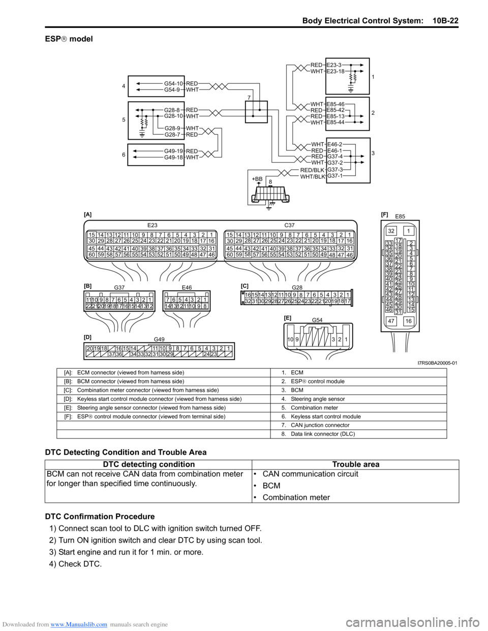
ESP® model
DTC Detecting Condition and Trouble Area
DTC Confirmation Procedure 1) Connect scan tool to DLC with ignition switch turned OFF.
2) Turn ON ignition switch and clear DTC by using scan tool.
3) Start engine and run it for 1 min. or more.
4) Check DTC.
[F] E85
161
15
2
3
4
5
6
7
8
9
10
11
12
13
14
17
18
19
20
21
22
23
24
25
26
27
28
29
30
31
3233
34
35
36
37
38
39
40
41
42
43
44
45
46
47
[D] 12345678910
11
141516
36 34 33 32 31 30 29 24 23
37
181920
G49
[A]
E23
C37
34
1819
567
10
11
17
20
47 46
495051
2122
52 16
25 9
24
14
29
5557 54 53
59
60 58 2
262728
15
30
56 4832 31
34353637
4042 39 38
44
45 43 41 331
1213
238
34
1819
567
10
11
17
20
47 46
495051
2122
52 16
25 9
24
14
29
5557 54 53
59
60 58 2
262728
15
30
56 4832 31
34353637
4042 39 38
44
45 43 41 331
12
13
238
[C]G28
1234567
8
910
11
1213141516
1718
19
20
212223242526272829303132
[E] G54
109 321
[B]
G37E46
1234567 1234567
8910
11
8910
11
121314 121314
1516171819202122
4
6 1
2
3
REDWHT
REDWHT
REDWHT
REDWHT
E23-3E23-18
E85-42E85-46
E85-13E85-44
G37-4G37-2
REDWHT
REDWHTG49-19G49-18
5
7
WHTG54-9REDG54-10
G28-8G28-10
G28-7REDG28-9WHT
RED/BLKWHT/BLK
REDWHTE46-1E46-2
G37-1G37-3
+BB8
I7RS0BA20005-01
[A]: ECM connector (viewed from harness side)
1. ECM
[B]: BCM connector (viewed from harness side) 2. ESP® control module
[C]: Combination meter connector (viewed from harness side) 3. BCM
[D]: Keyless start control module connector (viewed from harness side) 4. Steering angle sensor
[E]: Steering angle sensor connector (viewed from harness side) 5. Combination meter
[F]: ESP ® control module connector (viewed from terminal side) 6. Keyless start control module
7. CAN junction connector
8. Data link connector (DLC)
DTC detecting condition Trouble area
BCM can not receive CAN data from combination meter
for longer than specif ied time continuously. • CAN communication circuit
•BCM
• Combination meter
Page 1487 of 1496

Downloaded from www.Manualslib.com manuals search engine Keyless Start System: 10E-25
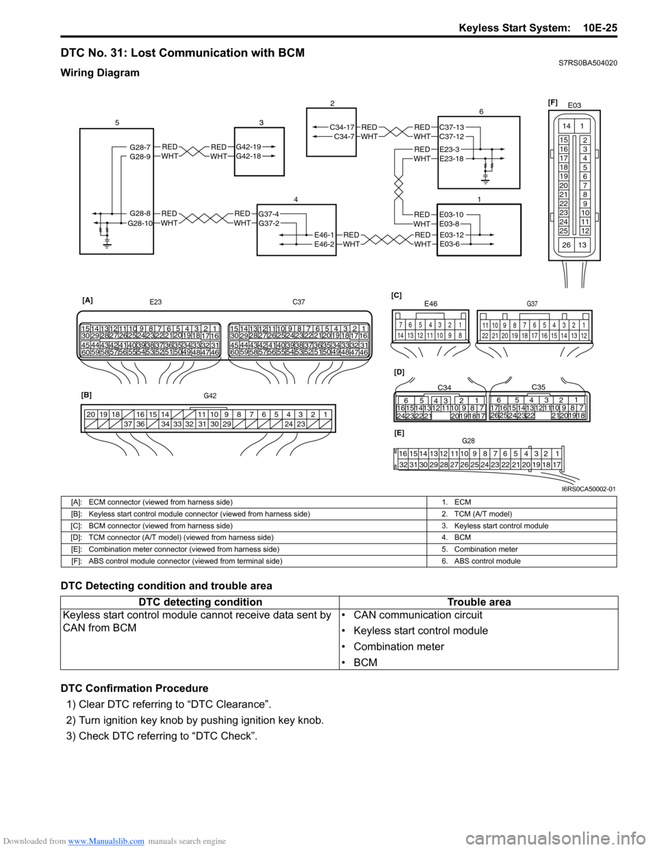
DTC No. 31: Lost Communication with BCMS7RS0BA504020
Wiring Diagram
DTC Detecting condition and trouble area
DTC Confirmation Procedure1) Clear DTC referring to “DTC Clearance”.
2) Turn ignition key knob by pushing ignition key knob.
3) Check DTC referring to “DTC Check”.
REDWHTE03-12E03-6
REDWHTE03-10E03-8
REDWHTREDWHTG42-19G42-18 3REDWHTREDWHT
REDWHTREDWHT
REDWHTE46-1
G37-4
G42-19G42-18
G28-8G28-10G37-2
C34-7
E46-2
C34-17
1
2
4
53
21
[A]
E23
G42 C37
34
1819
5671011
17
20
47 46
495051
2122
52 16
25 9
24
14
29
5557 54 53
59
60 58 2
262728
15
30
56 4832 31343536374042 39 38
44
45 43 41 331
1213
238
34
1819
5671011
17
20
47 46
495051
2122
52 16
25 9
24
14
29
5557 54 53
59
60 5826
27
28
15
30
56 4832 31343536374042 39 38
44
45 43 41 33
1213
238
[B] [D]
[C]
65
16 15141312 11 43
24 23 2122 10 9 8 7
21
1920 18 17
C34
17 16
26 25 15 14
65 3
42
13 12
23 2224 1110 9
212019 87
18
1
C35
[E]G28
12345678910111213141516
17181920212223242526272829303132
124
53
67
891011
1213141516171819202122
G37
E46
124
53
67
891011121314
1234567891011
141516
36 34 33 32 31 30 29 24 23
37
181920
G28-9G28-7REDWHTE23-3E23-18
REDWHTC37-13C37-12 6
[F]
E03
15
16
17
18
19
20
21
22
23
24
25 2
3
4
5
6
7
8
9
10
11
12
1
13
14
26
I6RS0CA50002-01
[A]: ECM connector (viewed from harness side)
1. ECM
[B]: Keyless start control module connector (v iewed from harness side) 2. TCM (A/T model)
[C]: BCM connector (viewed from harness side) 3. Keyless start control module
[D]: TCM connector (A/T model) (viewed from harness side) 4. BCM
[E]: Combination meter connector (viewed from harness side) 5. Combination meter
[F]: ABS control module connector (viewed from terminal side) 6. ABS control module
DTC detecting conditionTrouble area
Keyless start control module cannot receive data sent by
CAN from BCM • CAN communication circuit
• Keyless start control module
• Combination meter
•BCM