Fuse connector SUZUKI SWIFT 2007 2.G Service Workshop Manual
[x] Cancel search | Manufacturer: SUZUKI, Model Year: 2007, Model line: SWIFT, Model: SUZUKI SWIFT 2007 2.GPages: 1496, PDF Size: 34.44 MB
Page 1208 of 1496
Downloaded from www.Manualslib.com manuals search engine 9A-37 Wiring Systems:
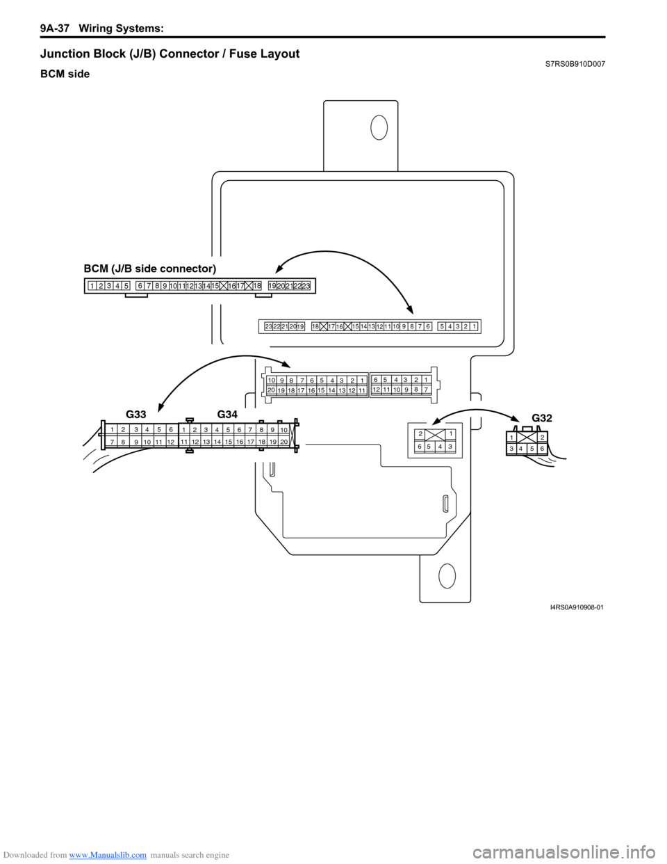
Junction Block (J/B) Connector / Fuse LayoutS7RS0B910D007
BCM side
21
65 3
4
43 2
121
11
14
13
15 598 7
176
16
19 18
20 1065 43 28
1
7
10 912
11
34 6 5
2
110
11 12 13 14 15 16 17 18 19 123456789
20
G34
G33
G32
BCM (J/B side connector)
34
1
2 5
15
14
12
13
10
11
9
8
6
7
17
161821 22
19
20
23
23
2221
20
19 18
1716 15 1413
1211
10
98 76
54
3 2
1
5
11 6
12
9108
7 2
1 4
3
I4RS0A910908-01
Page 1211 of 1496
Downloaded from www.Manualslib.com manuals search engine Wiring Systems: 9A-40
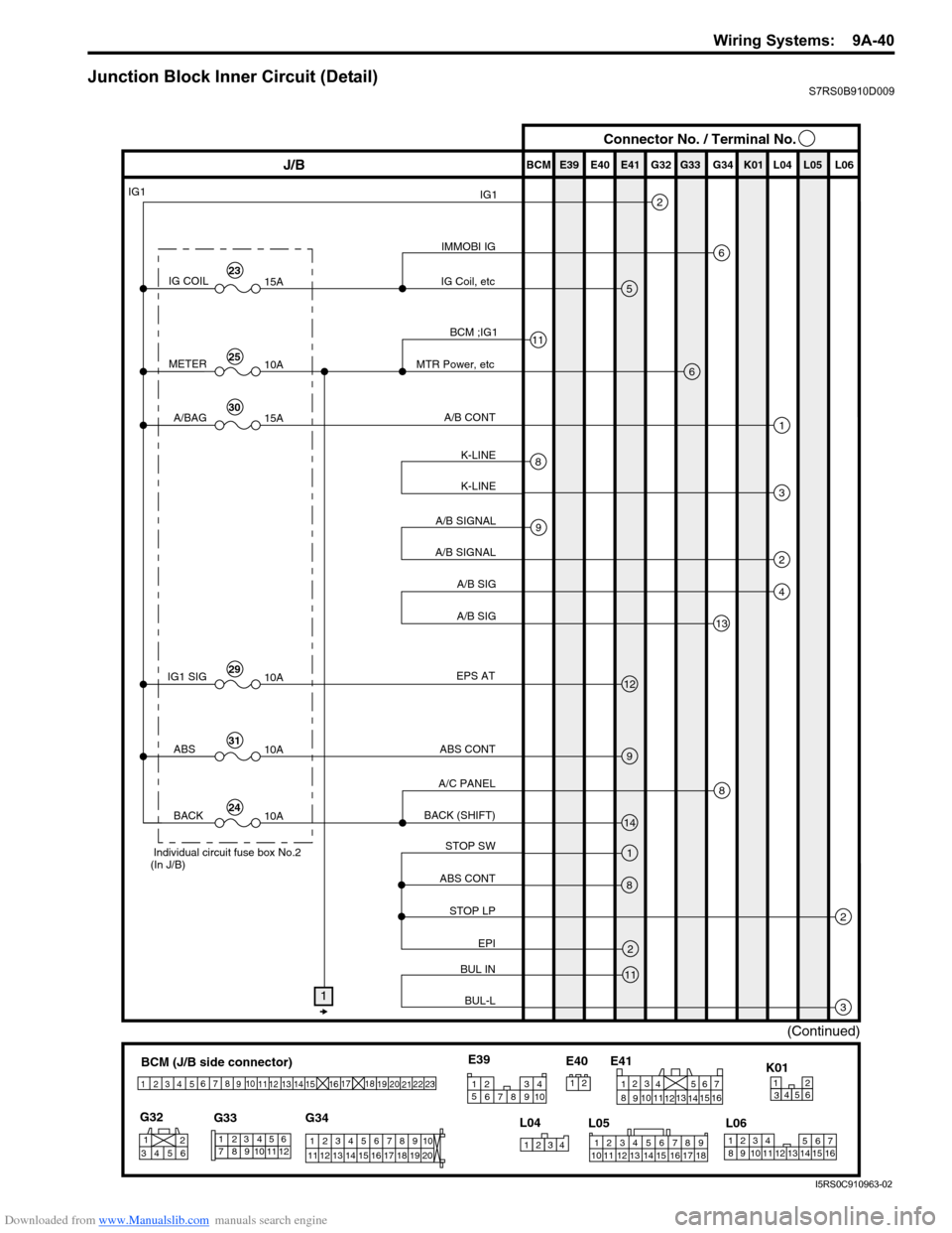
Junction Block Inner Circuit (Detail)S7RS0B910D009
BCM (J/B side connector)
34
1
2 5
15
14
12
13
10
11
9
8
6
7
17
161821 22
19
20
23
1234578 11 6
12
91034 6 52
1
G33
G32
G34
10
11 12 13 14 15 16 17 18 19 123456789
20
345612K01
23414
3
561214
11
10 157
2113 16
98
6
5
4
3
2
1
7
11
10
9
8
15
14
13
12 16
L04
L06
E41
21
123456789
15 16 17 18
1110 12 13 14
1
234
5 678 910
E39
L05
E40
IMMOBI IG
IG1
IG Coil, etc E39 E41E40
BCM G34G33G32 K01 L04 L05 L06
IG COIL
IG1
15A
METER10A
A/BAG15A
2
6
5
13
J/B Connector No. / Terminal No.
BCM ;IG1
MTR Power, etc
A/B CONT
K-LINE K-LINE
A/B SIGNAL
A/B SIGNAL
A/B SIG
A/B SIG
IG1 SIG 10AEPS AT
ABS CONT
STOP SW
ABS CONT
STOP LP EPI
BUL IN
BUL-L
BACK (SHIFT)
A/C PANEL
6
1
3
2
4
8
11
9
12
9
14
1
2
3
8
2
11
8
ABS
10A
BACK10A
1
(Continued)
Individual circuit fuse box No.2
(In J/B)
23
25
30
29
31
24
I5RS0C910963-02
Page 1212 of 1496
Downloaded from www.Manualslib.com manuals search engine 9A-41 Wiring Systems:
BCM (J/B side connector)
34
1
2 5
15
14
12
13
10
11
9
8
6
7
17
161821 22
19
20
23
1234578 11 6
12
91034 6 52
1
G33
G32
G34
10
11 12 13 14 15 16 17 18 19 123456789
20
345612K01
23414
3
561214
11
10 157
2113 16
98
6
5
4
3
2
1
7
11
10
9
8
15
14
13
12 16
L04
L06
E41
21
12 34 5 6 78 9
15 16 17 18
1110 12 13 14
1
234
5 678 910
E39
L05
E40
E39 E41E40
BCM G34G33G32K01 L04 L05 L06
11
J/B
Flasher Relay 78
2
5
1463
6
12
3
6
9
3
12
1
5
1
19
14
3
18
7
16
2
15
1
10
1Serial OUT
Serial INF DISP
HORN SW
HORN RELAY
GND SW-L SW-R
LP-LLP-R
IG
+B
HAZ HORN
SECURITY IN
ANSWER BACK HAZARD SW
METER (R)
FR TURN (R)
METER (L)
RR-TURN (R)
FR TURN (L) R-TURN (L)
TURN-R
TAIL SW
(HAZ, ASH,ILL) TURN-L
POSI LP TAIL LP,
LICENSE
TAIL BCM, WNG, etc
Lamp FL (FL BOX)
TAIL SW (Upper)
TAIL 10A
+B
D/L 20A
P/WT 20A D/L (+B)
32
(Continued)
Individual circuit fuse box No.2
(In J/B)
32
34
44
(Continued)
1
2
3
4
5
Connector No. / Terminal No.
2
18
I5RS0C910964-02
Page 1213 of 1496
Downloaded from www.Manualslib.com manuals search engine Wiring Systems: 9A-42
E39 E41E40
BCM G34G33G32 K01 L04 L05 L06J/B
7
17
8
5
4
14
2
23
1
6
3
(Continued)
DEF LP
RR DEF
RR DEF
CONTROL
RR-DEF RLY
EPI
A/C PANEL
LUGGAGE LAMP
BCM
DOME LP POWER
RR FOG SW
DEICER LP
DEICER
DEICER
CONTROL
DEICER
RLY
D/SL
D/SL-IN
RR DEF
DEICER/
RR FOG
MTA/HID R
RADIO
DIESEL/HID L 20A
15A 2
41
3
10A
15A
15A
IMMOBI 10A
2
41
39
43
40
42
35
(Continued)
Individual circuit fuse box No.2 (In J/B)
1
2
3
4
Connector No. / Terminal No.
BCM (J/B side connector)
3 4
1
2 5
15
14
12
13
10
11
9
8
6
7
17
161821 22
19
20
23
1234578 11 6
12
91034 6 52
1
G33
G32
G34
10
11 12 13 14 15 16 17 18 19 123456789
20
345612K01
23414
3
561214
11
10 157
2113 16
98
6
5
4
3
2
1
7
11
10
9
8
15
14
13
12 16
L04
L06
E41
21
123456789
15 16 17 18
1110 12 13 14
1
234
5 678 910
E39
L05
E40
Except Oceania
15
7
18
10
I5RS0C910904-03
Page 1214 of 1496
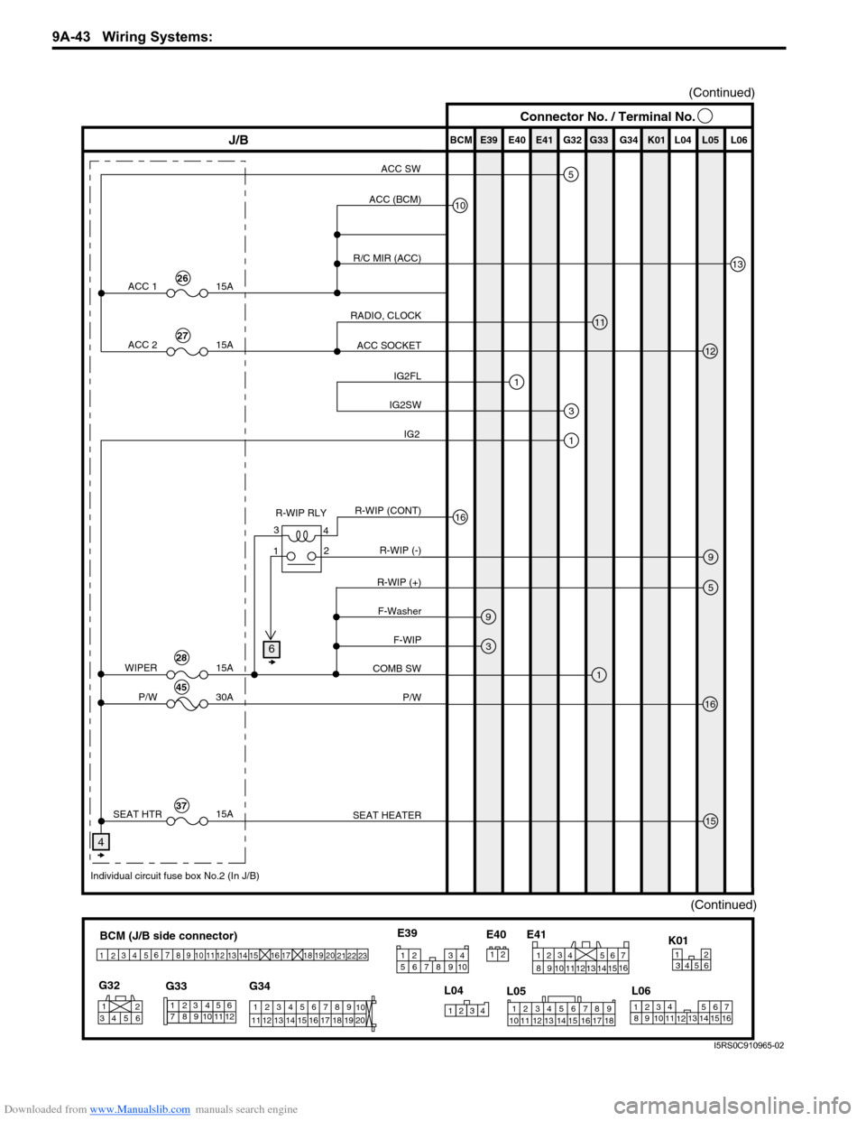
Downloaded from www.Manualslib.com manuals search engine 9A-43 Wiring Systems:
(Continued)
BCM (J/B side connector)
34
1
2 5
15
14
12
13
10
11
9
8
6
7
17
161821 22
19
20
23
1234578 11 6
12
91034 6 52
1
G33
G32
G34
10
11 12 13 14 15 16 17 18 19 123456789
20
345612K01
23414
3
561214
11
10 157
2113 16
98
6
5
4
3
2
1
7
11
10
9
8
15
14
13
12 16
L04
L06
E41
21
123456789
15 16 17 18
1110 12 13 14
1
234
5 678 910
E39
L05
E40
E39 E41E40
BCM G34G33G32K01 L04 L05 L06
9
J/B
10
11
13
12
3
1
16
1
9
1
3
16
15
5
ACC (BCM)
R/C MIR (ACC)
RADIO, CLOCK ACC SOCKET
IG2FL
R-WIP RLY R-WIP (+)F-Washer
F-WIP
COMB SW
P/W
SEAT HEATER
IG2SW
R-WIP (CONT) R-WIP (-)
ACC 1
P/W
SEAT HTR 15A
ACC 2
15A
30A
WIPER 15A
15A
(Continued)
26
27
28
45
Individual circuit fuse box No.2 (In J/B)
37
5ACC SW
4
4
3
2
1
Connector No. / Terminal No.
6
IG2
I5RS0C910965-02
Page 1215 of 1496
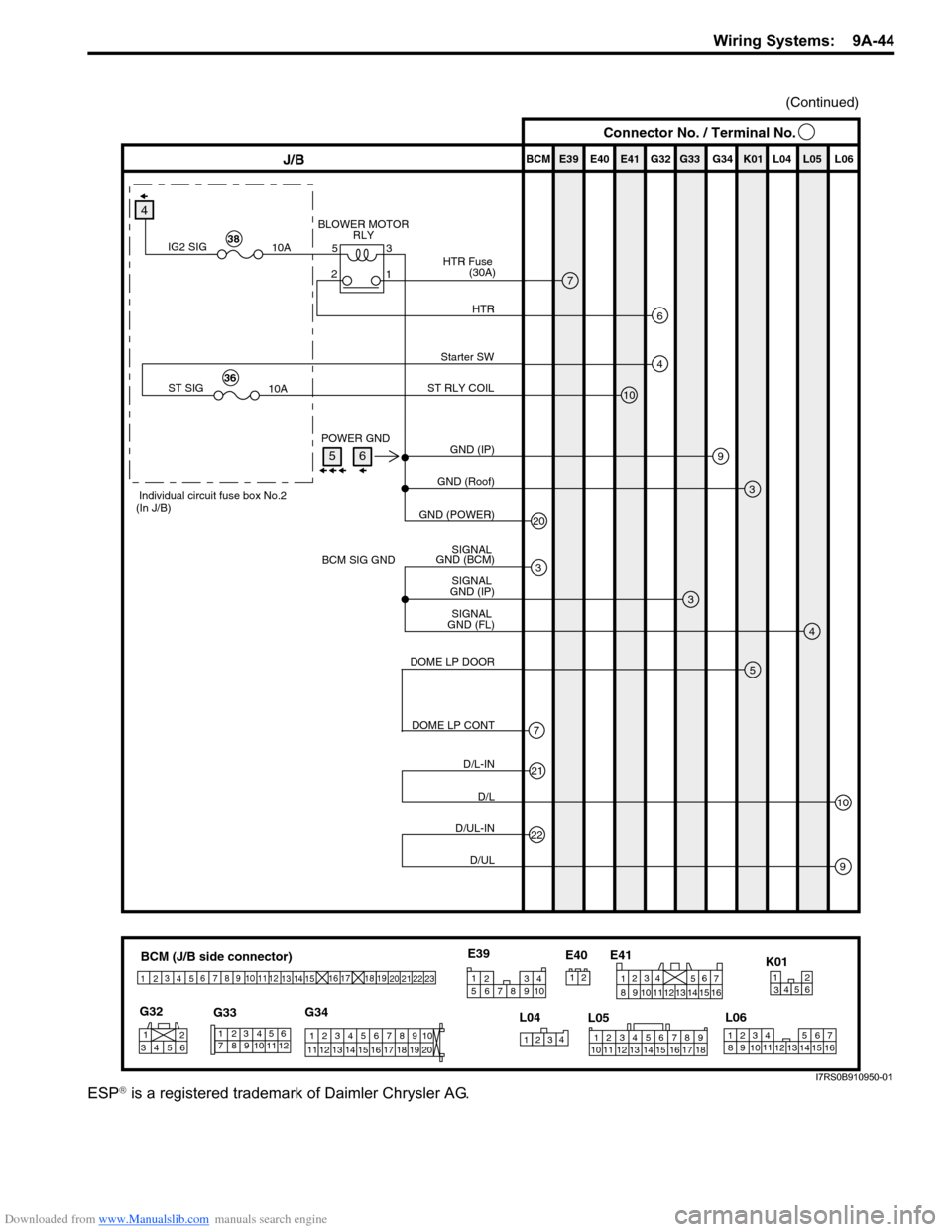
Downloaded from www.Manualslib.com manuals search engine Wiring Systems: 9A-44
ESP® is a registered trademark of Daimler Chrysler AG.
BCM (J/B side connector)
34
1
2 5
15
14
12
13
10
11
9
8
6
7
17
161821 22
19
20
23
1234578 11 6
12
91034 6 52
1
G33
G32
G34
10
11 12 13 14 15 16 17 18 19 123456789
20
345612K01
23414
3
561214
11
10 157
2113 16
98
6
5
4
3
2
1
7
11
10
9
8
15
14
13
12 16
L04
L06
E41
21
12 34 5 6 78 9
15 16 17 18
1110 12 13 14
1
234
5 678 910
E39
L05
E40
E39 E41E40
BCM G34G33G32 K01 L04 L05 L06J/B
9
3
3
20
3
4
(Continued)
GND (IP)
POWER GND
BCM SIG GND GND (Roof)
GND (POWER)
SIGNAL
GND (FL) SIGNAL
GND (IP) SIGNAL
GND (BCM)
4
4
10
Starter SW
ST RLY COIL
ST SIG 10A36
Individual circuit fuse box No.2
(In J/B)
7
6
BLOWER MOTOR RLY
HTR
HTR Fuse
(30A)
IG2 SIG 10A38
5
7
DOME LP DOOR
DOME LP CONT
21
22
10
9
D/L-IN D/L
D/UL-IND/UL
3
5
2 1
Connector No. / Terminal No.
56
I7RS0B910950-01
Page 1232 of 1496
Downloaded from www.Manualslib.com manuals search engine 9A-61 Wiring Systems:
50A
3
J/B
15ARADIO
40
2
15A
ACC 1
26
10
1
20AD/L
34
11
10A
METER
25
Main fuse box
WHT
E402
20
Blower motor relay
"Junction Block Inner circuit"
Relay
J/B (BCM- 20 )J/B (BCM- 17 )
17
2L04
9
3
83
B BG33
3
4L05
10
J/C
G15
BLK/ORN
BLK/ORN
16
BLK/ORN
"F-1"
YELPPL/WHT
A/B
SDM
14
316E417G34
Front
position light
"D-2"
"D-2, D-4, G-1"
J/B
RED/YELRED/YEL
J/C
L74D
DD
Licence plate light
"D-2"
YPW
"A-2"
Generator
E464
WHT/BLU
WB
RYRY
RYRYRY
Tail light
(R)
Tail light
(L)
"D-2"
RED/YEL
RED/YEL
RED/YEL
811
C CG37
J/C
G16
YEL
GRYYEL
GY
C
YEL
Y
"G-2"
Multi information
display Auto
unit
"E-2"
A
A
J/C
2E26
+B1
LOCK
ACC
ON
ST ACC IG1 IG2
STOUT
IN
+B2
BLUGRN
G3252
56G21
J/B side connector (BCM)
A
BCM
I7RS0B910919-01
Page 1251 of 1496
Downloaded from www.Manualslib.com manuals search engine Wiring Systems: 9A-80
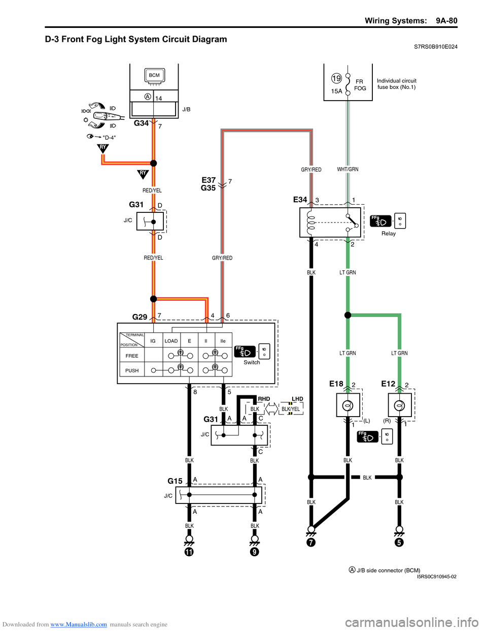
D-3 Front Fog Light System Circuit DiagramS7RS0B910E024
FR
FOG
(R)
(L)
1
E182
A
A
1
E122
15A
19
Relay
Switch
2
E343
4 1
WHT/GRNGRY/RED
GRY/RED
LT GRN
BLK
BLKBLKBLK
LT GRNLT GRN
7
D
DE37
G35
FREE IG LOAD E Il Ile
TERMINAL
POSITION
PUSH
6
7
4
8
G15
G31
G29
RED/YEL
RED/YEL
11
A
A
C
BLK
BLK
5
J/C
75
J/C
AC
J/C
G31
BLK
BLKBLK
BLK
RY
RY
"D-4"
BCM
14A
7G34
J/B
A
BLK
9
Individual circuit fuse box (No.1)
J/B side connector (BCM)
A
BLK
RHD
BLK/YEL
LHD
I5RS0C910945-02
Page 1307 of 1496
Downloaded from www.Manualslib.com manuals search engine Instrumentation / Driver Info. / Horn: 9C-12
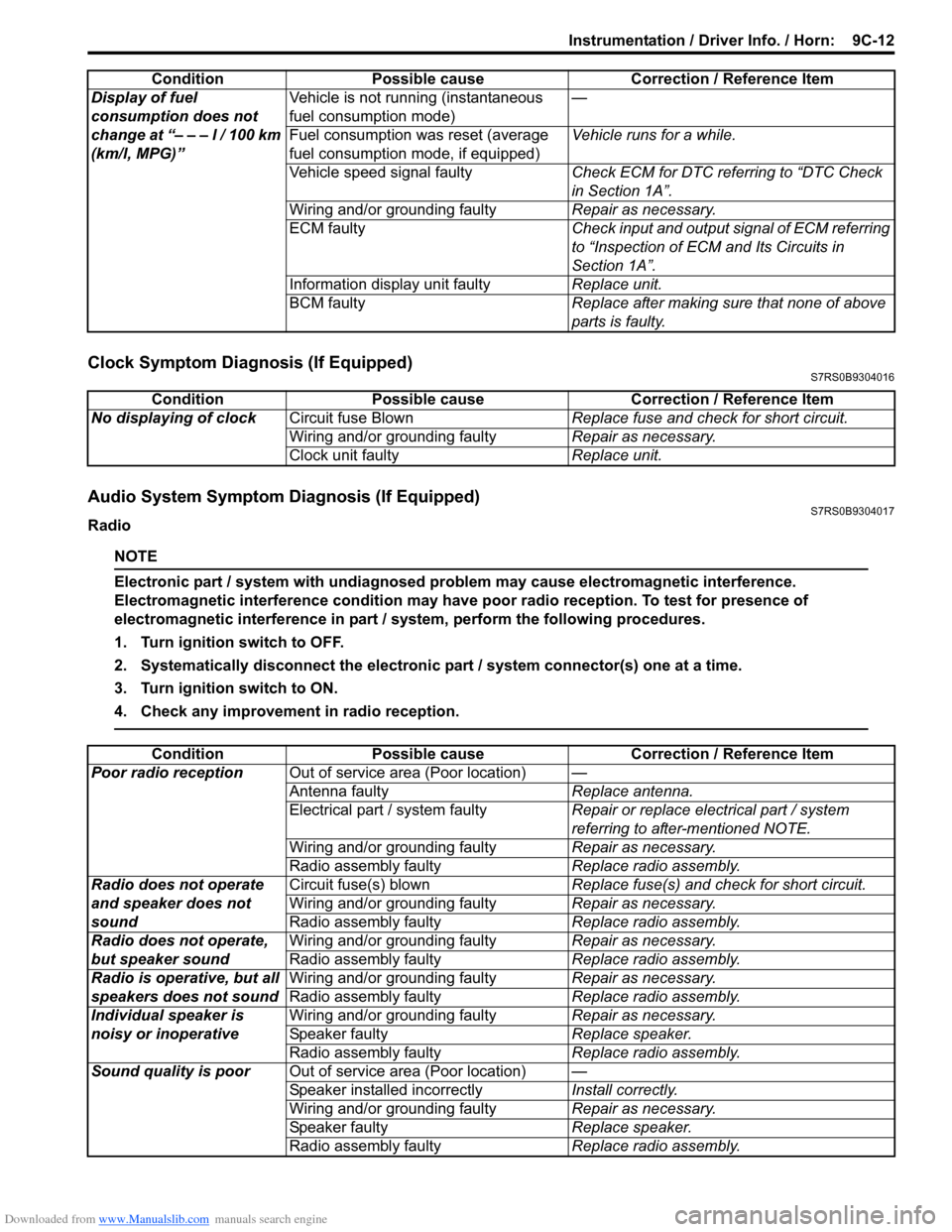
Clock Symptom Diagnosis (If Equipped)S7RS0B9304016
Audio System Symptom Diagnosis (If Equipped)S7RS0B9304017
Radio
NOTE
Electronic part / system with undiagnosed pr oblem may cause electromagnetic interference.
Electromagnetic interference condition may have poor radio reception. To test for presence of
electromagnetic interference in part / system, perform the following procedures.
1. Turn ignition switch to OFF.
2. Systematically disconnect the electronic part / system connector(s) one at a time.
3. Turn ignition switch to ON.
4. Check any improvement in radio reception.
Display of fuel
consumption does not
change at “– – – l / 100 km
(km/l, MPG)” Vehicle is not running (instantaneous
fuel consumption mode)
—
Fuel consumption was reset (average
fuel consumption mo de, if equipped)Vehicle runs for a while.
Vehicle speed signal faulty Check ECM for DTC referring to “DTC Check
in Section 1A”.
Wiring and/or grounding faulty Repair as necessary.
ECM faulty Check input and output signal of ECM referring
to “Inspection of ECM and Its Circuits in
Section 1A”.
Information display unit faulty Replace unit.
BCM faulty Replace after making sure that none of above
parts is faulty.
Condition Possible cause Correction / Reference Item
Condition
Possible cause Correction / Reference Item
No displaying of clock Circuit fuse Blown Replace fuse and check for short circuit.
Wiring and/or grounding faulty Repair as necessary.
Clock unit faulty Replace unit.
ConditionPossible cause Correction / Reference Item
Poor radio reception Out of service area (Poor location) —
Antenna faulty Replace antenna.
Electrical part / system faulty Repair or replace electrical part / system
referring to after-mentioned NOTE.
Wiring and/or grounding faulty Repair as necessary.
Radio assembly faulty Replace radio assembly.
Radio does not operate
and speaker does not
sound Circuit fuse(s) blown
Replace fuse(s) and check for short circuit.
Wiring and/or grounding faulty Repair as necessary.
Radio assembly faulty Replace radio assembly.
Radio does not operate,
but speaker sound Wiring and/or grounding faulty
Repair as necessary.
Radio assembly faulty Replace radio assembly.
Radio is operative, but all
speakers does not sound Wiring and/or grounding faulty
Repair as necessary.
Radio assembly faulty Replace radio assembly.
Individual speaker is
noisy or inoperative Wiring and/or grounding faulty
Repair as necessary.
Speaker faulty Replace speaker.
Radio assembly faulty Replace radio assembly.
Sound quality is poor Out of service area (Poor location) —
Speaker installed incorrectly Install correctly.
Wiring and/or grounding faulty Repair as necessary.
Speaker faulty Replace speaker.
Radio assembly faulty Replace radio assembly.
Page 1419 of 1496
Downloaded from www.Manualslib.com manuals search engine Body Electrical Control System: 10B-16
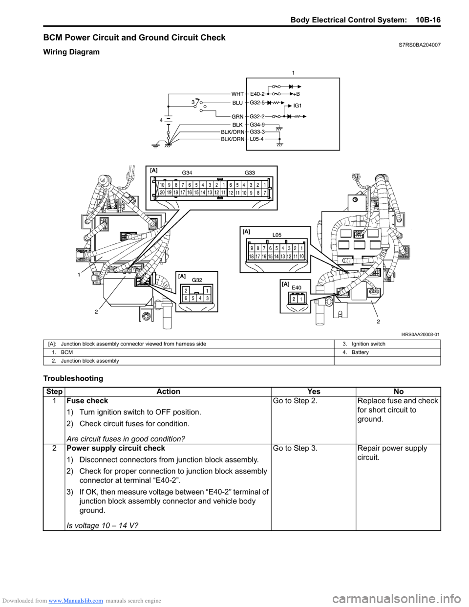
BCM Power Circuit and Ground Circuit CheckS7RS0BA204007
Wiring Diagram
Troubleshooting
I4RS0AA20008-01
[A]: Junction block assembly connector viewed from harness side3. Ignition switch
1. BCM 4. Battery
2. Junction block assembly
Step Action YesNo
1 Fuse check
1) Turn ignition switch to OFF position.
2) Check circuit fuses for condition.
Are circuit fuses in good condition? Go to Step 2.
Replace fuse and check
for short circuit to
ground.
2 Power supply circuit check
1) Disconnect connectors from junction block assembly.
2) Check for proper connection to junction block assembly
connector at terminal “E40-2”.
3) If OK, then measure voltage between “E40-2” terminal of junction block assembly connector and vehicle body
ground.
Is voltage 10 – 14 V? Go to Step 3.
Repair power supply
circuit.