1J- SUZUKI SWIFT 2007 2.G Service User Guide
[x] Cancel search | Manufacturer: SUZUKI, Model Year: 2007, Model line: SWIFT, Model: SUZUKI SWIFT 2007 2.GPages: 1496, PDF Size: 34.44 MB
Page 419 of 1496
Downloaded from www.Manualslib.com manuals search engine Charging System: 1J-9
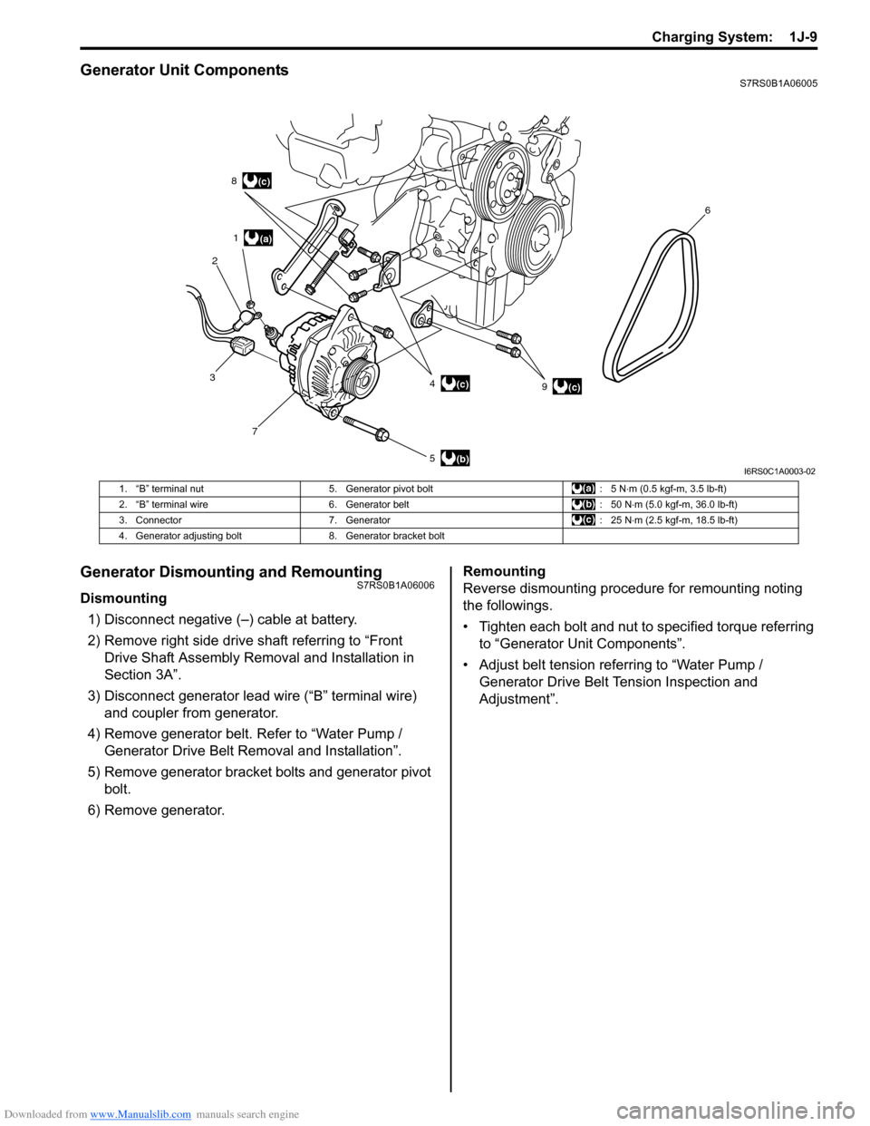
Generator Unit ComponentsS7RS0B1A06005
Generator Dismounting and RemountingS7RS0B1A06006
Dismounting1) Disconnect negative (–) cable at battery.
2) Remove right side drive shaft referring to “Front Drive Shaft Assembly Removal and Installation in
Section 3A”.
3) Disconnect generator lead wire (“B” terminal wire) and coupler from generator.
4) Remove generator belt. Refer to “Water Pump / Generator Drive Belt Re moval and Installation”.
5) Remove generator bracket bolts and generator pivot bolt.
6) Remove generator. Remounting
Reverse dismounting procedure for remounting noting
the followings.
• Tighten each bolt and nut to specified torque referring
to “Generator Unit Components”.
• Adjust belt tension referring to “Water Pump / Generator Drive Belt Tension Inspection and
Adjustment”.
(a)
(b)
(c)
1
2 8
3 7 5 49 6(c)
(c)
I6RS0C1A0003-02
1. “B” terminal nut
5. Generator pivot bolt : 5 N⋅m (0.5 kgf-m, 3.5 lb-ft)
2. “B” terminal wire 6. Generator belt : 50 N⋅m (5.0 kgf-m, 36.0 lb-ft)
3. Connector 7. Generator : 25 N⋅m (2.5 kgf-m, 18.5 lb-ft)
4. Generator adjusting bolt 8. Generator bracket bolt
Page 420 of 1496
Downloaded from www.Manualslib.com manuals search engine 1J-10 Charging System:
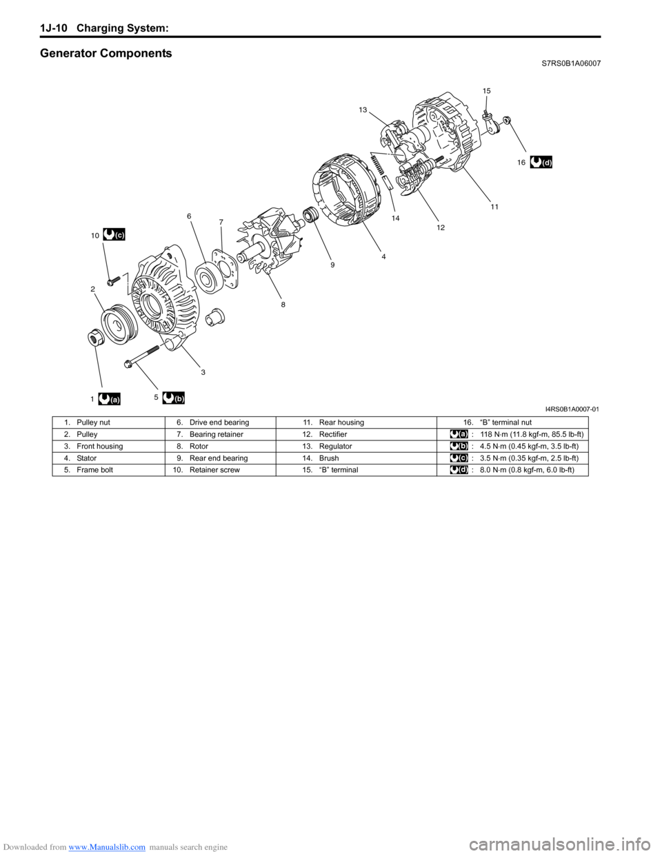
Generator ComponentsS7RS0B1A06007
1211
13
14
(a)(b)
(c)
(d)
1 2
3 4
56
7
89
10 15
16
I4RS0B1A0007-01
1. Pulley nut 6. Drive end bearing 11. Rear housing 16. “B” terminal nut
2. Pulley 7. Bearing retainer 12. Rectifier : 118 N⋅m (11.8 kgf-m, 85.5 lb-ft)
3. Front housing 8. Rotor 13. Regulator : 4.5 N⋅m (0.45 kgf-m, 3.5 lb-ft)
4. Stator 9. Rear end bearing 14. Brush : 3.5 N⋅m (0.35 kgf-m, 2.5 lb-ft)
5. Frame bolt 10. Retainer screw 15. “B” terminal : 8.0 N⋅m (0.8 kgf-m, 6.0 lb-ft)
Page 421 of 1496
Downloaded from www.Manualslib.com manuals search engine Charging System: 1J-11
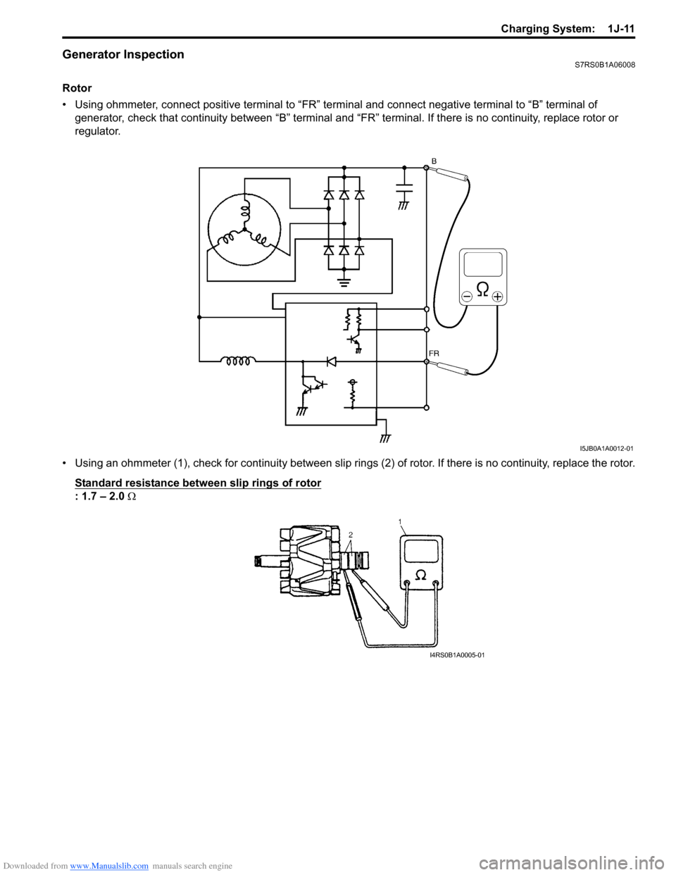
Generator InspectionS7RS0B1A06008
Rotor
• Using ohmmeter, connect positive terminal to “FR” terminal and connect negative terminal to “B” terminal of generator, check that continuity between “B” terminal and “FR” terminal. If there is no continuity, replace rotor or
regulator.
• Using an ohmmeter (1), check for continuity between slip ring s (2) of rotor. If there is no continuity, replace the rotor.
Standard resistance between slip rings of rotor
: 1.7 – 2.0 Ω
I5JB0A1A0012-01
I4RS0B1A0005-01
Page 422 of 1496
Downloaded from www.Manualslib.com manuals search engine 1J-12 Charging System:
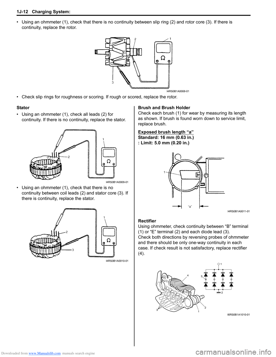
• Using an ohmmeter (1), check that there is no continuity between slip ring (2) and rotor core (3). If there is
continuity, replace the rotor.
• Check slip rings for roughness or scoring. If rough or scored, replace the rotor.
Stator
• Using an ohmmeter (1), check all leads (2) for continuity. If there is no co ntinuity, replace the stator.
• Using an ohmmeter (1), check that there is no continuity between coil leads (2) and stator core (3). If
there is continuity, replace the stator. Brush and Brush Holder
Check each brush (1) for wear by measuring its length
as shown. If brush is found worn down to service limit,
replace brush.
Exposed brush length “a”
Standard: 16 mm (0.63 in.)
: Limit: 5.0 mm (0.20 in.)
Rectifier
Using ohmmeter, check continuity between “B” terminal
(1) or “E” terminal (2) and each diode lead (3).
Check both directions by reversing probes of ohmmeter
and there should be only one-way continuity in each
case. If check result is not satisfactory, replace rectifier
(4).
I4RS0B1A0008-01
I4RS0B1A0009-01
I4RS0B1A0010-01
I4RS0B1A0011-01
1
1
3 3
2
2
4
I6RS0B1A1010-01
Page 423 of 1496
Downloaded from www.Manualslib.com manuals search engine Charging System: 1J-13
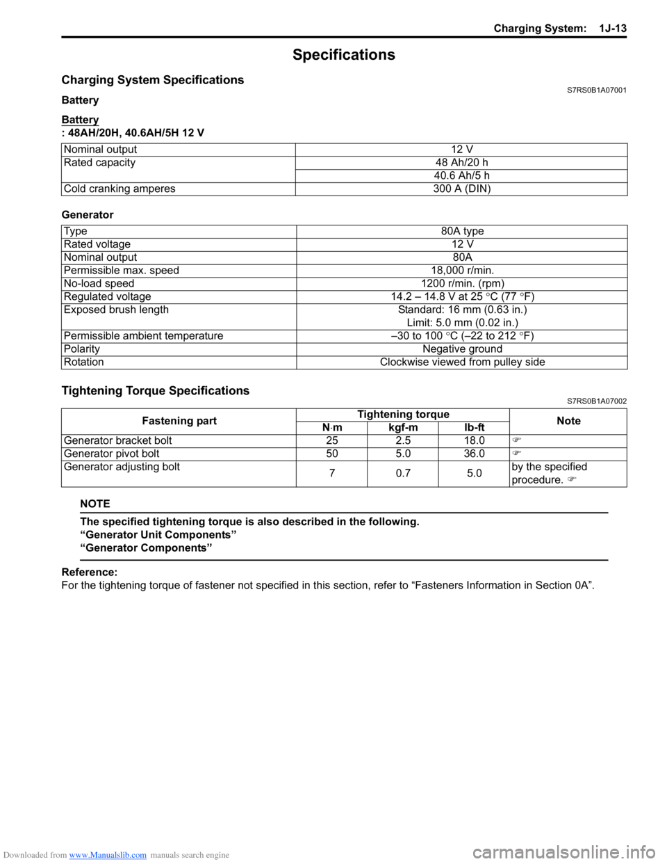
Specifications
Charging System SpecificationsS7RS0B1A07001
Battery
Battery
: 48AH/20H, 40.6AH/5H 12 V
Generator
Tightening Torque SpecificationsS7RS0B1A07002
NOTE
The specified tightening torque is also described in the following.
“Generator Unit Components”
“Generator Components”
Reference:
For the tightening torque of fastener not specified in this section, refer to “Fasteners Information in Section 0A”.
Nominal output
12 V
Rated capacity 48 Ah/20 h
40.6 Ah/5 h
Cold cranking amperes 300 A (DIN)
Ty p e 80A type
Rated voltage 12 V
Nominal output 80A
Permissible max. speed 18,000 r/min.
No-load speed 1200 r/min. (rpm)
Regulated voltage 14.2 – 14.8 V at 25 ° C (77 °F)
Exposed brush length Standard: 16 mm (0.63 in.)
Limit: 5.0 mm (0.02 in.)
Permissible ambient temperature –30 to 100 °C (–22 to 212 °F)
Polarity Negative ground
Rotation Clockwise viewed from pulley side
Fastening partTightening torque
Note
N ⋅mkgf-mlb-ft
Generator bracket bolt 25 2.5 18.0 �)
Generator pivot bolt 50 5.0 36.0 �)
Generator adjusting bolt 70.7 5.0by the specified
procedure.
�)