valve clearance SUZUKI SWIFT 2007 2.G Service User Guide
[x] Cancel search | Manufacturer: SUZUKI, Model Year: 2007, Model line: SWIFT, Model: SUZUKI SWIFT 2007 2.GPages: 1496, PDF Size: 34.44 MB
Page 291 of 1496
Downloaded from www.Manualslib.com manuals search engine Engine Mechanical: 1D-6
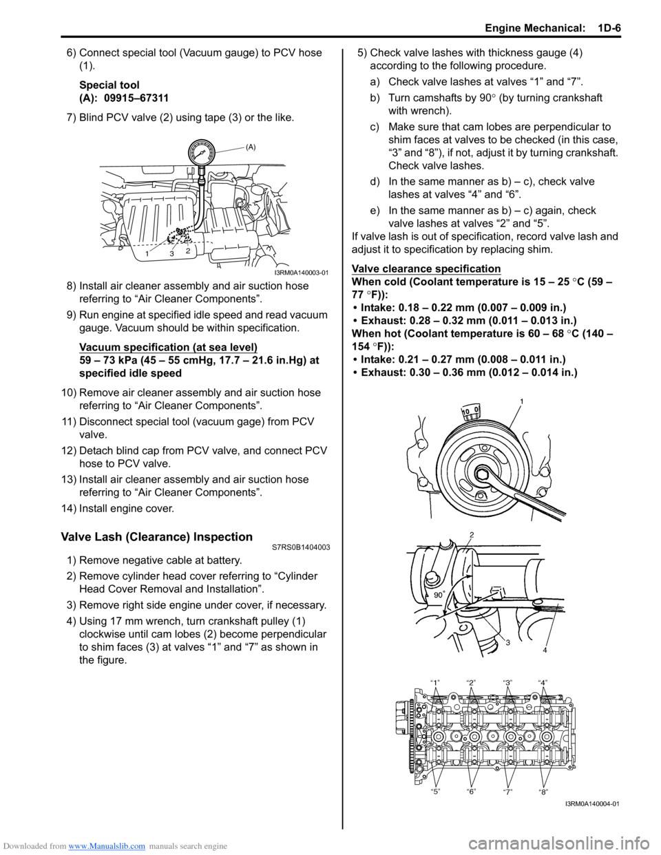
6) Connect special tool (Vacuum gauge) to PCV hose (1).
Special tool
(A): 09915–67311
7) Blind PCV valve (2) using tape (3) or the like.
8) Install air cleaner assembly and air suction hose referring to “Air Cleaner Components”.
9) Run engine at specified idle speed and read vacuum gauge. Vacuum should be within specification.
Vacuum specification (at sea level)
59 – 73 kPa (45 – 55 cmHg, 17.7 – 21.6 in.Hg) at
specified idle speed
10) Remove air cleaner assembly and air suction hose referring to “Air Cleaner Components”.
11) Disconnect special tool (vacuum gage) from PCV valve.
12) Detach blind cap from PCV valve, and connect PCV hose to PCV valve.
13) Install air cleaner assembly and air suction hose referring to “Air Cleaner Components”.
14) Install engine cover.
Valve Lash (Clearance) InspectionS7RS0B1404003
1) Remove negative cable at battery.
2) Remove cylinder head cover referring to “Cylinder Head Cover Removal and Installation”.
3) Remove right side engine under cover, if necessary.
4) Using 17 mm wrench, turn crankshaft pulley (1) clockwise until cam lobes (2) become perpendicular
to shim faces (3) at valves “1” and “7” as shown in
the figure. 5) Check valve lashes with thickness gauge (4)
according to the following procedure.
a) Check valve lashes at valves “1” and “7”.
b) Turn camshafts by 90 ° (by turning crankshaft
with wrench).
c) Make sure that cam lobes are perpendicular to shim faces at valves to be checked (in this case,
“3” and “8”), if not, adjust it by turning crankshaft.
Check valve lashes.
d) In the same manner as b) – c), check valve
lashes at valves “4” and “6”.
e) In the same manner as b) – c) again, check valve lashes at valves “2” and “5”.
If valve lash is out of specification, record valve lash and
adjust it to specification by replacing shim.
Valve clearance specification
When cold (Coolant te mperature is 15 – 25 °C (59 –
77 °F)):
• Intake: 0.18 – 0.22 mm (0.007 – 0.009 in.)
• Exhaust: 0.28 – 0.32 mm (0.011 – 0.013 in.)
When hot (Coolant temperature is 60 – 68 °C (140 –
154 °F)):
• Intake: 0.21 – 0.27 mm (0.008 – 0.011 in.)
• Exhaust: 0.30 – 0.36 mm (0.012 – 0.014 in.)
(A)
13 2
I3RM0A140003-01
I3RM0A140004-01
Page 292 of 1496
Downloaded from www.Manualslib.com manuals search engine 1D-7 Engine Mechanical:
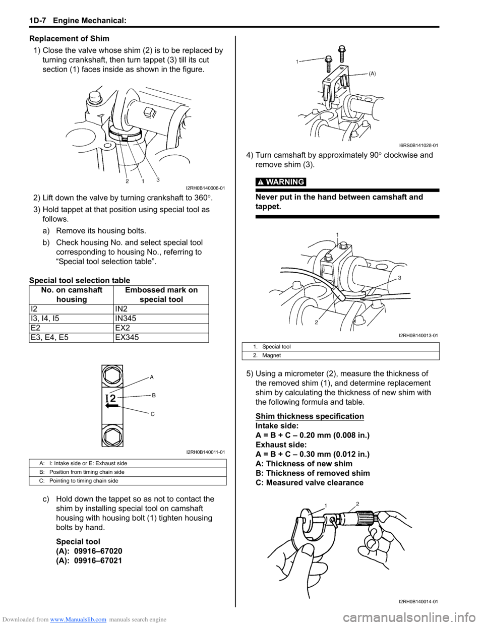
Replacement of Shim1) Close the valve whose shim (2) is to be replaced by turning crankshaft, then tu rn tappet (3) till its cut
section (1) faces inside as shown in the figure.
2) Lift down the valve by turning crankshaft to 360° .
3) Hold tappet at that position using special tool as follows.
a) Remove its housing bolts.
b) Check housing No. and select special tool corresponding to housing No., referring to
“Special tool selection table”.
Special tool selection table
c) Hold down the tappet so as not to contact the shim by installing special tool on camshaft
housing with housing bolt (1) tighten housing
bolts by hand.
Special tool
(A): 09916–67020
(A): 09916–67021 4) Turn camshaft by approximately 90
° clockwise and
remove shim (3).
WARNING!
Never put in the hand between camshaft and
tappet.
5) Using a micrometer (2), measure the thickness of the removed shim (1), and determine replacement
shim by calculating the thickness of new shim with
the following formula and table.
Shim thickness specification
Intake side:
A = B + C – 0.20 mm (0.008 in.)
Exhaust side:
A = B + C – 0.30 mm (0.012 in.)
A: Thickness of new shim
B: Thickness of removed shim
C: Measured valve clearance
No. on camshaft
housing Embossed mark on
special tool
I2 IN2
I3, I4, I5 IN345
E2 EX2
E3, E4, E5 EX345
A: I: Intake side or E: Exhaust side
B: Position from timing chain side
C: Pointing to timing chain side
I2RH0B140006-01
I2RH0B140011-01
1. Special tool
2. Magnet
I6RS0B141028-01
I2RH0B140013-01
I2RH0B140014-01
Page 293 of 1496
Downloaded from www.Manualslib.com manuals search engine Engine Mechanical: 1D-8
For example of intake side:
When thickness of removed shim is 2.40 mm (0.094
in.), and measured valve clearance is 0.45 mm
(0.018 in.).
A = 2.40 mm (0.094 in.) + 0.45 mm (0.018 in.) – 0.20
mm (0.008 in.) = 2.65 mm (0.104 in.)
Calculated thickness of new shim = 2.65 mm (0.104
in.)
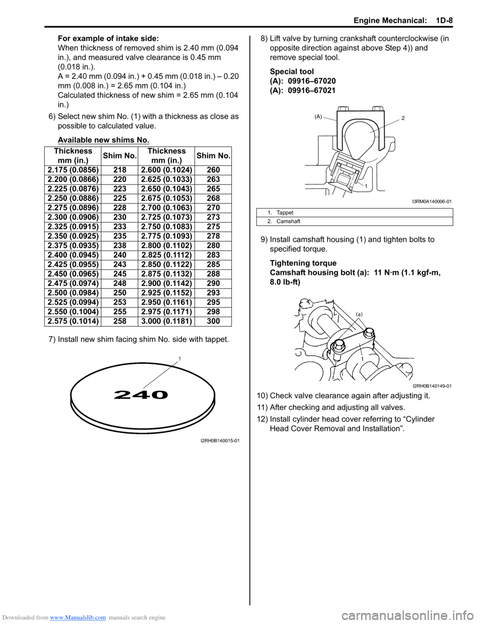
6) Select new shim No. (1) with a thickness as close as possible to calculated value.
Available new shims No.
7) Install new shim facing shim No. side with tappet. 8) Lift valve by turning crankshaft counterclockwise (in
opposite direction against above Step 4)) and
remove special tool.
Special tool
(A): 09916–67020
(A): 09916–67021
9) Install camshaft housing (1) and tighten bolts to specified torque.
Tightening torque
Camshaft housing bolt (a ): 11 N·m (1.1 kgf-m,
8.0 lb-ft)
10) Check valve clearance again after adjusting it. 11) After checking and adjusting all valves.
12) Install cylinder head cover referring to “Cylinder Head Cover Removal and Installation”.
Thickness
mm (in.) Shim No.Thickness
mm (in.) Shim No.
2.175 (0.0856) 218 2.600 (0.1024) 260
2.200 (0.0866) 220 2.625 (0.1033) 263
2.225 (0.0876) 223 2.650 (0.1043) 265
2.250 (0.0886) 225 2.675 (0.1053) 268
2.275 (0.0896) 228 2.700 (0.1063) 270
2.300 (0.0906) 230 2.725 (0.1073) 273
2.325 (0.0915) 233 2.750 (0.1083) 275
2.350 (0.0925) 235 2.775 (0.1093) 278
2.375 (0.0935) 238 2.800 (0.1102) 280
2.400 (0.0945) 240 2.825 (0.1112) 283
2.425 (0.0955) 243 2.850 (0.1122) 285
2.450 (0.0965) 245 2.875 (0.1132) 288
2.475 (0.0974) 248 2.900 (0.1142) 290
2.500 (0.0984) 250 2.925 (0.1152) 293
2.525 (0.0994) 253 2.950 (0.1161) 295
2.550 (0.1004) 255 2.975 (0.1171) 298
2.575 (0.1014) 258 3.000 (0.1181) 300
I2RH0B140015-01
1. Tappet
2. Camshaft
(A)2
1
I3RM0A140006-01
I2RH0B140149-01
Page 316 of 1496
Downloaded from www.Manualslib.com manuals search engine 1D-31 Engine Mechanical:
7) Install camshaft housing.
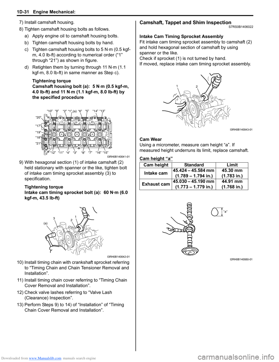
8) Tighten camshaft housing bolts as follows.a) Apply engine oil to camshaft housing bolts.
b) Tighten camshaft housing bolts by hand.
c) Tighten camshaft housing bolts to 5 N ⋅m (0.5 kgf-
m, 4.0 lb-ft) according to numerical order (“1”
through “21”) as shown in figure.
d) Retighten them by turning through 11 N⋅ m (1.1
kgf-m, 8.0 lb-ft) in same manner as Step c).
Tightening torque
Camshaft housing bolt (a): 5 N ⋅m (0.5 kgf-m,
4.0 lb-ft) and 11 N ⋅m (1.1 kgf-m, 8.0 lb-ft) by
the specified procedure
9) With hexagonal section (1) of intake camshaft (2) held stationary with spanner or the like, tighten bolt
of intake cam timing sp rocket assembly (3) to
specification.
Tightening torque
Intake cam timing sprocket bolt (a): 60 N·m (6.0
kgf-m, 43.5 lb-ft)
10) Install timing chain with cr ankshaft sprocket referring
to “Timing Chain and Chain Tensioner Removal and
Installation”.
11) Install timing chain cover referring to “Timing Chain Cover Removal and Installation”.
12) Check valve lashes referring to “Valve Lash (Clearance) Inspection”.
13) Perform Steps 9) to 14) of “Installation” of “Timing Chain Cover Removal and Installation”.Camshaft, Tappet and Shim InspectionS7RS0B1406022
Intake Cam Timing Sprocket Assembly
Fit intake cam timing sprocket assembly to camshaft (2)
and hold hexagonal section of camshaft by using
spanner or the like.
Check if sprocket (1) is not turned by hand.
If moved, replace intake ca m timing sprocket assembly.
Cam Wear
Using a micrometer, measure cam height “a”. If
measured height underruns its limit, replace camshaft.
Cam height “a”
“10”“9” “2” “1”,(a) “6” “5” “14” “13”
“20”
“17” “19”
“18”
“21”
“12”“11”
“4” “3” “8” “7” “16” “15”
I3RH0B140041-01
1
2
3
(a)
I3RH0B140042-01
Cam height Standard Limit
Intake cam 45.424 – 45.584 mm
(1.789 – 1.794 in.) 45.30 mm
(1.783 in.)
Exhaust cam 45.030 – 45.190 mm
(1.773 – 1.779 in.) 44.91 mm
(1.768 in.)
2
1
I3RH0B140043-01
I2RH0B140080-01
Page 325 of 1496
Downloaded from www.Manualslib.com manuals search engine Engine Mechanical: 1D-40
Valves and Valve Guides InspectionS7RS0B1406026
Valve Guide
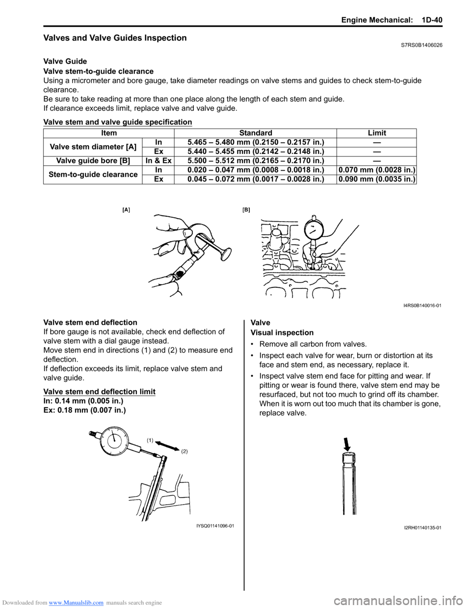
Valve stem-to-guide clearance
Using a micrometer and bore gauge, take diameter readings on valve stems and guides to check stem-to-guide
clearance.
Be sure to take reading at more than one place along the length of each stem and guide.
If clearance exceeds limit, replace valve and valve guide.
Valve stem and valve guide specification
Valve stem end deflection
If bore gauge is not available, check end deflection of
valve stem with a dial gauge instead.
Move stem end in directions (1) and (2) to measure end
deflection.
If deflection exceeds its limit, replace valve stem and
valve guide.
Valve stem end deflection limit
In: 0.14 mm (0.005 in.)
Ex: 0.18 mm (0.007 in.) Va l v e
Visual inspection
• Remove all carbon from valves.
• Inspect each valve for wear, burn or distortion at its
face and stem end, as necessary, replace it.
• Inspect valve stem end face for pitting and wear. If pitting or wear is found there, valve stem end may be
resurfaced, but not too much to grind off its chamber.
When it is worn out too much that its chamber is gone,
replace valve.
Item Standard Limit
Valve stem diameter [A] In 5.465 – 5.480 mm (0.2150 – 0.2157 in.) —
Ex 5.440 – 5.455 mm (0.2142 – 0.2148 in.) —
Valve guide bore [B] In & Ex 5.500 – 5.512 mm (0.2165 – 0.2170 in.) —
Stem-to-guide clearance In 0.020 – 0.047 mm (0.0008 – 0.
0018 in.) 0.070 mm (0.0028 in.)
Ex 0.045 – 0.072 mm (0.0017 – 0. 0028 in.) 0.090 mm (0.0035 in.)
I4RS0B140016-01
IYSQ01141096-01I2RH01140135-01
Page 328 of 1496
Downloaded from www.Manualslib.com manuals search engine 1D-43 Engine Mechanical:
Valve Spring InspectionS7RS0B1406028
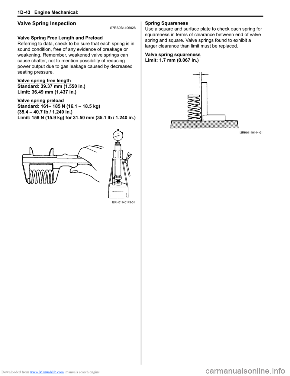
Valve Spring Free Length and Preload
Referring to data, check to be sure that each spring is in
sound condition, free of any evidence of breakage or
weakening. Remember, weakened valve springs can
cause chatter, not to mention possibility of reducing
power output due to gas leakage caused by decreased
seating pressure.
Valve spring free length
Standard: 39.37 mm (1.550 in.)
Limit: 36.49 mm (1.437 in.)
Valve spring preload
Standard: 161– 185 N (16.1 – 18.5 kg)
(35.4 – 40.7 lb / 1.240 in.)
Limit: 159 N (15.9 kg) for 31.50 mm (35.1 lb / 1.240 in.) Spring Squareness
Use a square and surface plate to check each spring for
squareness in terms of clearance between end of valve
spring and square. Valve springs found to exhibit a
larger clearance than limit must be replaced.
Valve spring squareness
Limit: 1.7 mm (0.067 in.)
I2RH01140143-01
I2RH01140144-01
Page 349 of 1496
Downloaded from www.Manualslib.com manuals search engine Engine Mechanical: 1D-64
Honing or Reboring Cylinders1) When any cylinder needs reboring, all other cylinders must also be rebored at the same time.
2) Select oversized piston according to amount of cylinder wear.
Oversize piston specification
Oversize 0.50: 78.453 – 78.468 mm (3.0887 –
3.0893 in.)
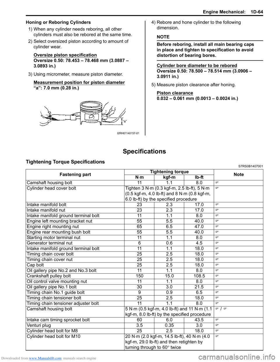
3) Using micrometer, measure piston diameter. Measurement position for piston diameter
“a”: 7.0 mm (0.28 in.) 4) Rebore and hone cylinder to the following
dimension.
NOTE
Before reboring, install all main bearing caps
in place and tighten to specification to avoid
distortion of bearing bores.
Cylinder bore diameter to be rebored
Oversize 0.50: 78.500 – 78.514 mm (3.0906 –
3.0911 in.)
5) Measure piston clearance after honing. Piston clearance
0.032 – 0.061 mm (0.0013 – 0.0024 in.)
Specifications
Tightening Torque SpecificationsS7RS0B1407001
I2RH01140157-01
Fastening part Tightening torque
Note
N ⋅mkgf-mlb-ft
Camshaft housing bolt 11 1.1 8.0 �)
Cylinder head cover bolt Tighten 3 N ⋅m (0.3 kgf-m, 2.5 lb-ft), 5 N ⋅m
(0.5 kgf-m, 4.0 lb-ft) and 8 N ⋅m (0.8 kgf-m,
6.0 lb-ft) by the specified procedure �)
Intake manifold bolt 23 2.3 17.0 �)
Intake manifold nut 23 2.3 17.0 �)
Intake manifold ground terminal bolt 11 1.1 8.0 �)
Engine left mounting bracket nut 55 5.5 40.0 �)
Engine right mounting nut 65 6.5 47.0 �)
Engine rear mounting bush bolt 55 5.5 40.0 �)
Starting motor terminal nut 11 1.1 8.0 �)
Generator terminal nut 6 0.6 4.5 �)
Intake manifold ground terminal bolt 11 1.1 18.0 �)
Timing chain cover bolt 25 2.5 18.0 �)
Timing chain cover nut 25 2.5 18.0 �)
Cap bolt 25 2.5 18.0 �)
Oil gallery pipe No.2 and No.3 bolt 11 1.1 8.0 �)
Crankshaft pulley bolt 150 15.0 108.5 �)
Oil control valve mounting nut 11 1.1 8.0 �)
Oil gallery pipe No.1 bolt 30 3.0 21.5 �)
Timing chain No.1 guide bolt 9 0.9 6.5 �)
Timing chain tensioner bolt 25 2.5 18.0 �)
Timing chain tensioner adjuster bolt 11 1.1 8.0 �)
Camshaft housing bolt 5 N ⋅m (0.5 kgf-m, 4.0 lb-ft) and 11 N ⋅m (1.1
kgf-m, 8.0 lb-ft) by the specified procedure �)
/ �)
Intake cam timing sprocket bolt 60 6.0 43.5 �)
Venturi plug 3.5 0.35 3.0 �)
Cylinder head bolt for M8 25 2.5 18.0 �)
Cylinder head bolt for M10 20 N ⋅m (2.0 kgf-m, 14.5 lb-ft), 40 N ⋅m (4.0
kgf-m, 29.0 lb-ft) and then retighten by
turning through to 60 ° twice �)
Page 362 of 1496
Downloaded from www.Manualslib.com manuals search engine 1E-10 Engine Lubrication System:
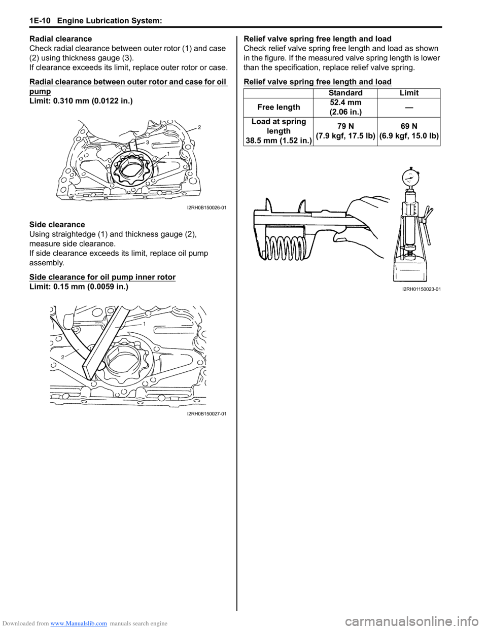
Radial clearance
Check radial clearance between outer rotor (1) and case
(2) using thickness gauge (3).
If clearance exceeds its limit, replace outer rotor or case.
Radial clearance between outer rotor and case for oil
pump
Limit: 0.310 mm (0.0122 in.)
Side clearance
Using straightedge (1) and thickness gauge (2),
measure side clearance.
If side clearance exceeds its limit, replace oil pump
assembly.
Side clearance for oil pump inner rotor
Limit: 0.15 mm (0.0059 in.)Relief valve spring free length and load
Check relief valve spring free length and load as shown
in the figure. If the measured valve spring length is lower
than the specification, replace relief valve spring.
Relief valve spring free length and load
I2RH0B150026-01
I2RH0B150027-01
Standard Limit
Free length 52.4 mm
(2.06 in.) —
Load at spring length
38.5 mm (1.52 in.) 79 N
(7.9 kgf, 17.5 lb) 69 N
(6.9 kgf, 15.0 lb)
I2RH01150023-01
Page 475 of 1496
Downloaded from www.Manualslib.com manuals search engine Wheels and Tires: 2D-8
Tire Mounting and DismountingS7RS0B2406004
CAUTION!
When installing tire which has arrow
indicating tire rotation direction to wheel,
make sure that this tire rotation direction is
same as actual tire rotation direction when
vehicle is moving forward. Otherwise, it is
not possible to install wheel with tire to
vehicle in specified direction.
Use a tire changing machine to mount or dismount tires.
Follow equipment manufacturer’s instructions. Do not
use hand tools or tire irons al one to change tires as they
may damage tire beads or wheel rim.
Rim bead seats should be cleaned with a wire brush or
coarse steel wool to remove lubricants, old rubber and
light rust. Before mounting or dismounting a tire, bead
area should be well lubricated with approved tire
lubricant.
After mounting, inflate to specified pressure shown on
tire placard so that beads are completely seated.
WARNING!
Do not stand over tire when inflating. Bead
may break when bead snaps over rim’s safety
hump and cause serious personal injury.
Do not exceed 330 kpa (47.9 psi) pressure
when inflating. If 330 kpa (47.9 psi) pressure
will not seat beads, deflate, re-lubricate and
reinflate.
Over inflation may cause bead to break and
cause serious personal injury.
Install valve core and inflate to proper pressure.
Tire RepairS7RS0B2406005
There are many different materials and techniques on
the market to repair tires. As not all of these work on all
types of tires, tire manufacturers have published detailed
instructions on how and when to repair tires. These
instructions can be obtained from each tire
manufacturer.
Tire Repair for Emergency Repaired-Tire with
Sealant
S7RS0B2406006
WARNING!
Be sure to observe “Precaution for
Emergency Flat Tire Repair Kit”. Otherwise,
your health may be ruined.
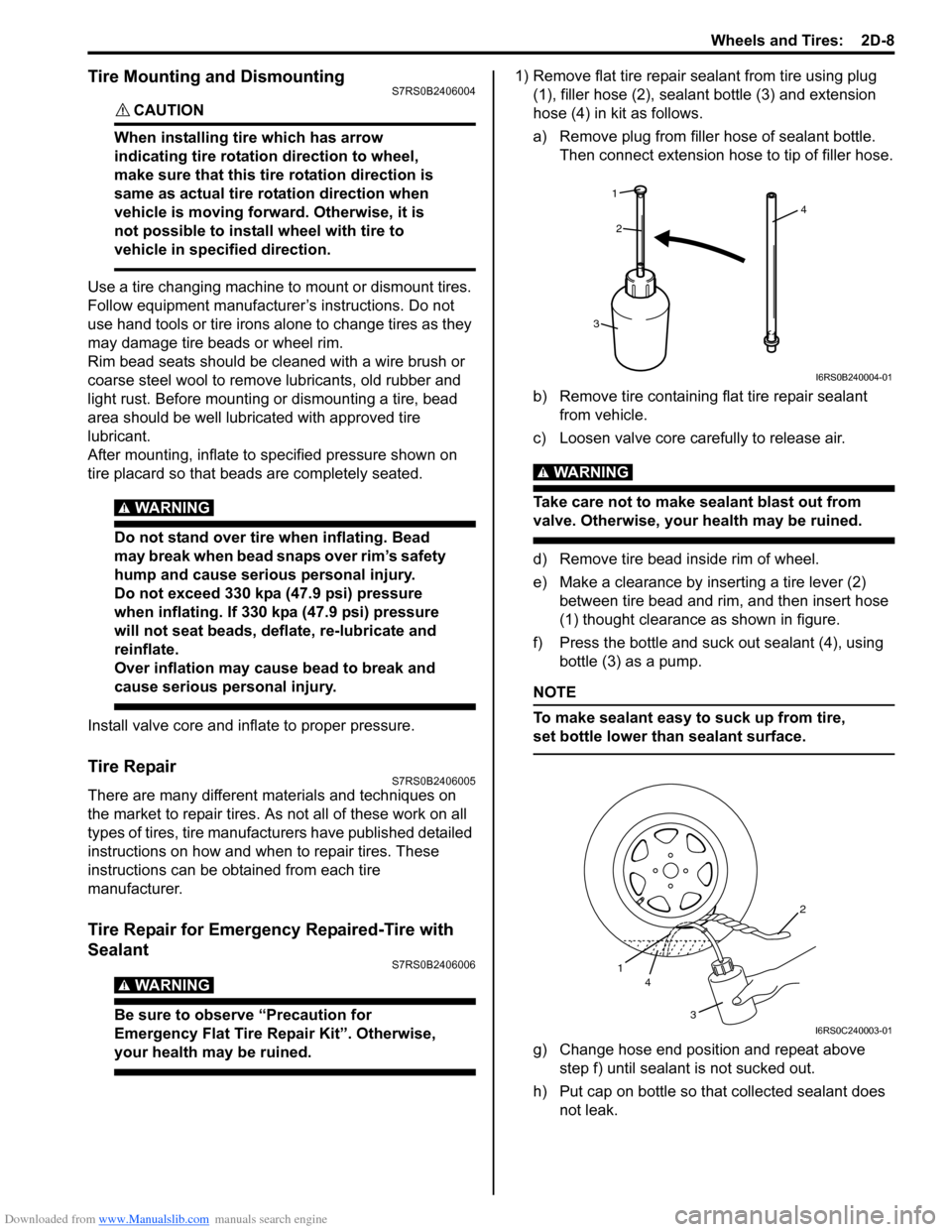
1) Remove flat tire repair sealant from tire using plug (1), filler hose (2), sealant bottle (3) and extension
hose (4) in kit as follows.
a) Remove plug from fille r hose of sealant bottle.
Then connect ext ension hose to tip of filler hose.
b) Remove tire containing flat tire repair sealant from vehicle.
c) Loosen valve core carefully to release air.
WARNING!
Take care not to make sealant blast out from
valve. Otherwise, your health may be ruined.
d) Remove tire bead inside rim of wheel.
e) Make a clearance by inserting a tire lever (2) between tire bead and rim, and then insert hose
(1) thought clearance as shown in figure.
f) Press the bottle and suck out sealant (4), using bottle (3) as a pump.
NOTE
To make sealant easy to suck up from tire,
set bottle lower than sealant surface.
g) Change hose end position and repeat above step f) until sealant is not sucked out.
h) Put cap on bottle so that collected sealant does not leak.
4
1
2
3
I6RS0B240004-01
1 4
3 2
I6RS0C240003-01
Page 496 of 1496

Downloaded from www.Manualslib.com manuals search engine 4-ii Table of Contents
Repair Instructions ..............................................4D-2Parking Brake Inspection and Adjustment ..........4D-2
Parking Brake Cable Removal and Installation ......................................................... 4D-3
Parking Brake Lever Removal and Installation ....4D-3
Specifications .... ...................................................4D-4
Tightening Torque Specifications ........................4D-4
ABS ........................................... .................4E-1
Precautions........................................................... 4E-1
Precautions in Diagnosing Troubles ................... 4E-1
Precautions in On-Vehicle Service...................... 4E-1
Precautions in Hydraulic Unit Operation Check ................................................................ 4E-1
General Description ............................................. 4E-2 ABS Description .................................................. 4E-2
ABS Hydraulic Unit / Control Module Assembly Description ....................................... 4E-2
CAN Communication System Description........... 4E-3
Schematic and Routing Diagram ........................ 4E-4 ABS Schematic ................................................... 4E-4
ABS Wiring Circuit Diagram ................................ 4E-5
Component Location ........... ................................ 4E-7
ABS Components Location ................................. 4E-7
Front Wheel Speed Sensor Components Location ............................................................ 4E-7
Rear Wheel Speed Sensor Components Location ............................................................ 4E-8
Diagnostic Information and Procedures ............ 4E-8 ABS Check .......................................................... 4E-8
ABS Warning Light Check................................. 4E-10
EBD Warning Light (Brake Warning Light) Check .............................................................. 4E-10
DTC Check........................................................ 4E-11
DTC Table ......................................................... 4E-11
DTC Clearance ................................................. 4E-12
Scan Tool Data ................................................. 4E-12
ABS Warning Light Does Not Come ON at Ignition Switch ON .......................................... 4E-13
ABS Warning Light Comes ON Steady ............. 4E-14
EBD Warning Light (Brake Warning Light) Comes ON Steady .......................................... 4E-15
Serial Data Link Circuit Check .......................... 4E-16
DTC C1021, C1022 / C1025, C1026 / C1031, C1032 / C1035, C1036: Right-Front / Left-
Front / Right-Rear / Left-Rear Wheel Speed
Sensor Circuit or Sensor Ring ........................ 4E-18
DTC C1041 / C1045 / C1051 / C1055, DTC C1042 / C1046 / C1052 / C1056: Right-Front
/ Left-Front / Right-Rear / Left-Rear Inlet
Solenoid Circuit, Right-Front / Left-Front /
Right-Rear / Left-Rear Outlet Solenoid
Circuit .............................................................. 4E-20
DTC C1057: Power Source Circuit ................... 4E-21
DTC C1061: ABS Pump Motor and/or Motor Driver Circuit ................................................... 4E-22
DTC C1063: Solenoid Valve Power Supply Driver Circuit ................................................... 4E-23
DTC C1071: ABS Control Module..................... 4E-24 DTC U1073: Control Module Communication
Bus Off ............................................................ 4E-25
DTC U1100: Lost Communication with ECM (Reception Error)............................................. 4E-27
Repair Instructions ............ ................................ 4E-28
ABS Hydraulic Unit Operati on Check................ 4E-28
ABS Hydraulic Unit / Control Module
Assembly Components ...... ............................. 4E-29
ABS Hydraulic Unit / Control Module
Assembly On-Vehicle Inspection .................... 4E-29
ABS Hydraulic Unit / Control Module
Assembly Removal and Inst allation ................ 4E-29
Front / Rear Wheel Speed Sensor On-Vehicle Inspection ........................................................ 4E-31
Front Wheel Speed Sensor Removal and Installation ....................................................... 4E-32
Front Wheel Speed Sensor Inspection ............. 4E-32
Rear Wheel Speed Sensor Removal and Installation ....................................................... 4E-33
Rear Wheel Speed Sensor Inspection .............. 4E-34
Front Wheel Encoder On-Veh icle Inspection .... 4E-34
Front wheel Enco der Removal and
Installation ....................................................... 4E-34
Rear Wheel Encoder On-Veh icle Inspection..... 4E-34
Rear Wheel Encoder Removal and Installation ....................................................... 4E-34
Specifications ..................... ................................ 4E-35
Tightening Torque Specifications ...................... 4E-35
Special Tools and Equipmen t ........................... 4E-35
Special Tool ...................................................... 4E-35
Electronic Stability Prog ram ...................4F-1
Precautions ........................................................... 4F-1
Precautions in Diagnosing Troubles ................... 4F-1
Precautions in On-Vehicle Service...................... 4F-1
Precautions in Hydraulic Unit Operation Check ................................................................ 4F-1
Precautions in Sensor Calibration ....................... 4F-1
Precautions in Speedometer Test or Other Tests ................................................................. 4F-2
General Description ............................................. 4F-2 Electronic Stability Program Description ............. 4F-2
Electronic Stability Program Construction ........... 4F-3
ESP® Hydraulic Unit / Control Module
Assembly Description........................................ 4F-5
Warning Lamp, Indicator Lamp Description ........ 4F-6
CAN Communication System Description........... 4F-6
CAN Communication System For Electronic Stability Program Description ............................ 4F-7
Schematic and Routing Diagram ........................ 4F-8 Electronic Stability Program Schematic .............. 4F-8
Electronic Stability Program Wiring Circuit Diagram............................................................. 4F-9
Component Location ............ ............................. 4F-11
Electronic Stability Program Component
Location........................................................... 4F-11
Diagnostic Information and Procedures .......... 4F-12 Electronic Stability Program System Check ...... 4F-12
ESP® Warning lamp Check .............................. 4F-14