valve clearance SUZUKI SWIFT 2007 2.G Service Owner's Manual
[x] Cancel search | Manufacturer: SUZUKI, Model Year: 2007, Model line: SWIFT, Model: SUZUKI SWIFT 2007 2.GPages: 1496, PDF Size: 34.44 MB
Page 497 of 1496

Downloaded from www.Manualslib.com manuals search engine Table of Contents 4-iii
ABS Warning Lamp Check ............................... 4F-14
EBD Warning Lamp (Brake Warning Lamp) Check .............................................................. 4F-15
DTC Check ....................................................... 4F-15
DTC Table ......................................................... 4F-15
DTC Clearance ................................................. 4F-18
Fail-Safe Table ................ .................................. 4F-19
Scan Tool Data ................................................. 4F-20
Visual Inspection ............................................... 4F-21
ESP ® Warning Lamp Does Not Come ON at
Ignition Switch ON .......................................... 4F-21
ESP ® Warning Lamp Comes ON Steady......... 4F-22
ABS Warning Lamp Does Not Come ON at Ignition Switch ON .......................................... 4F-23
ABS Warning Lamp Comes ON Steady............ 4F-24
EBD Warning Lamp (Brake Warning Lamp) Comes ON Steady .......................................... 4F-24
Serial Data Link Circuit Check .......................... 4F-26
DTC C1016: Stop Lamp Swit ch Circuit Failure .. 4F-28
DTC C1017 / C1023: Yaw Rate / G Sensor Assembly Failure ............................................ 4F-29
DTC C1018: Brake Fluid Le vel Switch Failure .. 4F-30
DTC 1020: Master Cylinder Pressure Sensor Power Supply Failure ...................................... 4F-31
DTC C1021, C1022 / C1025, C1026 / C1031, C1032 / C1035, C1036: Wheel Speed
Sensor Circuit or Encode r Failure ................... 4F-32
DTC C1024: Steering Angle Sensor Circuit
Failure ............................................................. 4F-34
DTC C1027: ESP ® OFF Switch Circuit
Failure ............................................................. 4F-34
DTC C1028: Master Cylinder Pressure Sensor Circuit Failure ....... .............................. 4F-35
DTC C1034: Yaw Rate / G Sensor Assembly Power Supply Failure ...................................... 4F-36
DTC C1037: Steering Angle Sensor Power Supply Failure ................................................. 4F-37
DTC C1038: Steering Angle Sensor Detect Rolling Counter Fa ilure from ESP® Control
Module ............................................................ 4F-38
DTC C1039: Yaw Rate / G Sensor Assembly Internal Failure .............. .................................. 4F-39
DTC C1040: Stability Control System Function Failure .............................................. 4F-39
DTC C1041 / C1042 / C1043 / C1044 / C1045 / C1046 / C1051 / C1052 / C1053 / C1054 /
C1055 / C1056: Solenoid Circuit Failure ......... 4F-40
DTC C1057: ESP ® Control Module Power
Supply Circuit Failure .... .................................. 4F-41
DTC C1061: Pump Motor and/or Motor Driver Circuit Failure .................................................. 4F-42
DTC C1063: Solenoid Valve Power Supply Driver Circuit Failure ....................................... 4F-43
DTC 1071: ESP ® Control Module Internal
Defect.............................................................. 4F-44 DTC C1073: Lost Communication With Yaw
Rate / G Sensor Assembly .............................. 4F-45
DTC C1075 / 1076 / 1078: Sensor Calibration Incomplete.......................... ............................. 4F-46
DTC C1090: Invalid Communication with
ECM ................................................................ 4F-47
DTC C1091 / C1094: ECM Data in CAN Line Failure / Invalid Torque Control
Communication with ECM .. ............................. 4F-48
DTC U1073: Control Module Communication Bus Off ............................................................ 4F-49
DTC U1100: Lost Communication with ECM (Reception Error)............................................. 4F-50
DTC U1126: Lost Communication with Steering Angle Sensor (Reception Error)........ 4F-51
DTC U1140: Lost Communication with BCM (Reception Error)............................................. 4F-52
Repair Instructions ........... ................................. 4F-54
ESP® Hydraulic Unit Operation Check ............. 4F-54
Sensor Calibration............................................. 4F-54
ESP® Hydraulic Unit / Control Module
Assembly On-Vehicle Inspection .................... 4F-55
ESP ® Hydraulic
Unit / Control Module
Assembly Removal and Inst allation ................ 4F-56
Front / Rear Wheel Speed Sensor On-Vehicle Inspection ........................................................ 4F-57
Front Wheel Speed Sensor Removal and Installation ....................................................... 4F-58
Front Wheel Speed Sensor Inspection ............. 4F-59
Rear Wheel Speed Sensor Removal and Installation ....................................................... 4F-59
Rear Wheel Speed Sensor Inspection .............. 4F-60
Front Wheel Encode r On-Vehicle Inspection .... 4F-61
Front Wheel Encoder Removal and Installation ....................................................... 4F-61
Rear Wheel Encoder On-Veh icle Inspection..... 4F-61
Rear Wheel Encoder Removal and Installation ....................................................... 4F-61
Master Cylinder Pressure Sensor On-Vehicle
Inspection ........................................................ 4F-61
Yaw Rate / G Sensor Assembly On-Vehicle Inspection ........................................................ 4F-62
Yaw Rate / G Sensor Assembly Removal and Installation ....................................................... 4F-63
Yaw Rate / G Sensor Inspection ....................... 4F-64
Steering Angle Sensor On-Vehicle Inspection .. 4F-64
Steering Angle Sensor Removal and Installation ....................................................... 4F-65
Steering Angle Sensor Inspection ..................... 4F-65
ESP® OFF Switch Removal an d Installation .... 4F-65
ESP® OFF Switch Inspection ........................... 4F-65
Specifications .................... ................................. 4F-66
Tightening Torque Specifications ...................... 4F-66
Special Tools and Equipmen t ........................... 4F-66
Special Tool ...................................................... 4F-66
Page 664 of 1496

Downloaded from www.Manualslib.com manuals search engine 5A-20 Automatic Transmission/Transaxle:
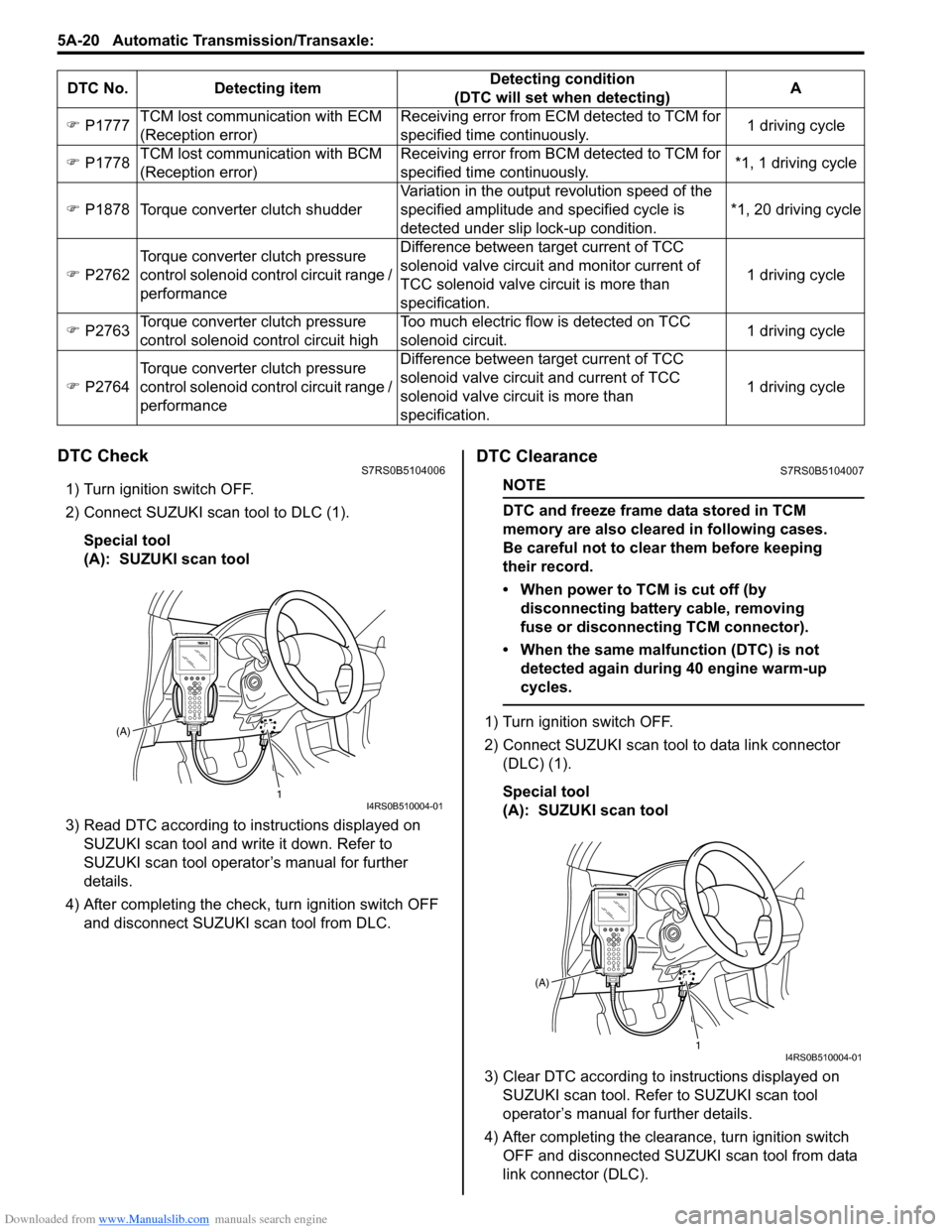
DTC CheckS7RS0B5104006
1) Turn ignition switch OFF.
2) Connect SUZUKI scan tool to DLC (1).
Special tool
(A): SUZUKI scan tool
3) Read DTC according to instructions displayed on SUZUKI scan tool and wr ite it down. Refer to
SUZUKI scan tool operator’s manual for further
details.
4) After completing the check, turn ignition switch OFF
and disconnect SUZUKI scan tool from DLC.
DTC ClearanceS7RS0B5104007
NOTE
DTC and freeze frame data stored in TCM
memory are also cleared in following cases.
Be careful not to clear them before keeping
their record.
• When power to TCM is cut off (by disconnecting battery cable, removing
fuse or disconnecting TCM connector).
• When the same malfunction (DTC) is not detected again during 40 engine warm-up
cycles.
1) Turn ignition switch OFF.
2) Connect SUZUKI scan tool to data link connector (DLC) (1).
Special tool
(A): SUZUKI scan tool
3) Clear DTC according to instructions displayed on SUZUKI scan tool. Refer to SUZUKI scan tool
operator’s manual for further details.
4) After completing the clearance, turn ignition switch OFF and disconnected SUZUKI scan tool from data
link connector (DLC).
�)
P1777 TCM lost communication with ECM
(Reception error) Receiving error from ECM detected to TCM for
specified time continuously.
1 driving cycle
�) P1778 TCM lost communication with BCM
(Reception error) Receiving error from BCM detected to TCM for
specified time continuously.
*1, 1 driving cycle
�) P1878 Torque converter clutch shudder Variation in the output revolution speed of the
specified amplitude and specified cycle is
detected under slip lock-up condition. *1, 20 driving cycle
�) P2762 Torque converter clutch pressure
control solenoid control circuit range /
performance Difference between target current of TCC
solenoid valve circuit and monitor current of
TCC solenoid valve ci
rcuit is more than
specification. 1 driving cycle
�) P2763 Torque converter clutch pressure
control solenoid control circuit high Too much electric flow is detected on TCC
solenoid circuit.
1 driving cycle
�) P2764 Torque converter clutch pressure
control solenoid control circuit range /
performance Difference between target current of TCC
solenoid valve circuit and current of TCC
solenoid valve circuit is more than
specification.
1 driving cycle
DTC No. Detecting item
Detecting condition
(DTC will set when detecting) A
1
(A)I4RS0B510004-01
1
(A)I4RS0B510004-01
Page 934 of 1496

Downloaded from www.Manualslib.com manuals search engine 7-ii Table of Contents
Recommended Service Material ....................... 7B-33
Special Tool ...................................................... 7B-33
Automatic Type .................... .................................7B-34
Precautions.........................................................7B-34 A/C System Caution .......................................... 7B-34
Precautions in Diagnosing Trouble ................... 7B-34
Precautions on Servicing A/C System .............. 7B-34
General Description .......... .................................7B-34
Auto A/C System Descript ion ............................ 7B-34
HVAC Control Module Operation Description ... 7B-36
Refrigerant Type Identifica tion .......................... 7B-36
Sub-Cool A/C System Description .................... 7B-36
A/C Operation Description ................................ 7B-36
On-Board Diagnostic System Description ......... 7B-37
Schematic and Routing Diagram ......................7B-37 Major Components of A/C System .................... 7B-37
A/C System Wiring Diagra m ............................. 7B-38
Diagnostic Information and Procedures ..........7B-39 A/C System Symptom Diagnosis ...................... 7B-39
Abnormal Noise Sympto m Diagnosis of A/C
System ............................................................ 7B-42
DTC Check........................................................ 7B-42
DTC Clearance ................................................. 7B-43
DTC Table ......................................................... 7B-44
Fail-Safe Table ................. ................................. 7B-45
Scan Tool Data ................................................. 7B-46
Air Conditioning System Check......................... 7B-47
Visual Inspection ............................................... 7B-49
DTC B1502: Inside Air Temperature Sensor and/or Its Circuit Malfunction .......................... 7B-49
DTC B1503: A/C Evaporator Air Temperature Sensor and/or Its Circuit Malfunction .............. 7B-50
DTC B1504: Sunload Sensor and/or Its Circuit Malfunction ......... ................................. 7B-52
DTC B1511: Temperature Control Actuator (Position Sensor) and/or Its Circuit
Malfunction ...................................................... 7B-53
DTC B1512: Air flow Control Actuator (Position Sensor) and/or Its Circuit
Malfunction ...................................................... 7B-55
DTC B1513: Temperature Control Actuator and/or Its Circuit Malfunction .......................... 7B-57
DTC B1514: Air Flow Co ntrol Actuator and/or
Its Circuit Malfunction ...................................... 7B-60
DTC B1541: HVAC Control Module Back-Up Power Supply Malfunction .............................. 7B-62
DTC B1546: A/C Refrigerant Pressure Malfunction ...................................................... 7B-63
DTC B1551: Serial Communication Circuit Malfunction ...................................................... 7B-63
DTC B1552: Serial Communication Signal Malfunction ...................................................... 7B-64
DTC B1553: CAN Communication Signal Malfunction ...................................................... 7B-65
DTC B1557: Vehicle Speed Sensor Signal Malfunction ...................................................... 7B-65
DTC B1561: Engine Coolant Temperature Sensor Signal Malfunctio n .............................. 7B-66 DTC B1562: Outside Air Temperature Sensor
Signal Malfunction ........................................... 7B-66
DTC B1563: A/C Refr igerant Pressure
Sensor Signal Malfunction .............................. 7B-66
Inspection of HVAC Control Module and Its Circuit .............................................................. 7B-67
A/C System Performance Inspection ................ 7B-70
A/C System Inspection at ECM ......................... 7B-70
Repair Instructions ............ ................................7B-71
Operation Procedure for Refrigerant Charge .... 7B-71
HVAC Unit Components ................................... 7B-72
HVAC Unit Removal and In stallation ................ 7B-73
Temperature Control Actuator Removal and Installation ....................................................... 7B-73
Temperature Control Actuat or Inspection ......... 7B-73
Air Flow Control Actuator Removal and Installation ....................................................... 7B-74
Air Flow Control Actuator Inspection ................. 7B-74
Air Intake Control Actuator Removal and Installation ....................................................... 7B-75
Air Intake Control Actuator Inspection............... 7B-75
Actuator Linkage Inspection .............................. 7B-76
Blower Motor Controller Removal and Installation ....................................................... 7B-76
Blower Motor Controller Inspection ................... 7B-76
HVAC Control Module Removal and Installation ....................................................... 7B-77
Sunload Sensor Removal and Installation ........ 7B-77
Sunload Sensor Inspection ............................... 7B-77
Outside Air Temperature Sensor Removal and Installation ................................................ 7B-77
Outside Air Temperature Sensor Inspection ..... 7B-77
Inside Air Temperature Sensor Removal and Installation ....................................................... 7B-78
Inside Air Temperature Sens or Inspection ........ 7B-78
Condenser Assembly On-Vehicle Inspection .... 7B-78
Condenser Assembly Removal and Installation ....................................................... 7B-78
Receiver/Dryer Removal and Installation .......... 7B-78
Evaporator Inspection ....................................... 7B-78
Evaporator Temperature Sensor Removal and Installation ................................................ 7B-78
Evaporator Temperature Se nsor Inspection ..... 7B-78
Expansion Valve Removal an d Installation ....... 7B-78
Expansion Valve Inspection .............................. 7B-78
A/C Refrigerant Pressure Sensor and Its Circuit Inspection............................................. 7B-78
A/C Refrigerant Pressu re Sensor Removal
and Installation ................................................ 7B-78
Compressor Relay Inspection .
.......................... 7B-78
Compressor Drive Belt Inspection and Adjustment ...................................................... 7B-78
Compressor Drive Belt Removal and Installation ....................................................... 7B-79
Compressor Assembly Removal and Installation ....................................................... 7B-79
Compressor Assembly Components................. 7B-79
Magnet Clutch Removal and Installation........... 7B-79
Magnet Clutch Inspection.................................. 7B-79
Relief Valve Inspection...................................... 7B-79
Page 968 of 1496

Downloaded from www.Manualslib.com manuals search engine 7B-20 Air Conditioning System: Manual Type
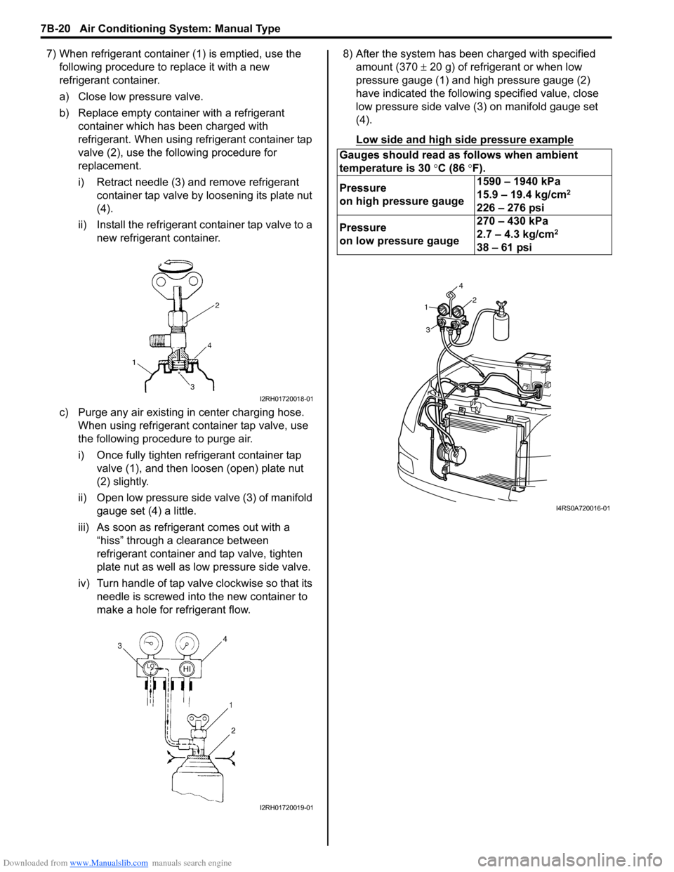
7) When refrigerant container (1) is emptied, use the following procedure to replace it with a new
refrigerant container.
a) Close low pressure valve.
b) Replace empty container with a refrigerant container which has been charged with
refrigerant. When using refrigerant container tap
valve (2), use the following procedure for
replacement.
i) Retract needle (3) and remove refrigerant container tap valve by loosening its plate nut
(4).
ii) Install the refrigerant container tap valve to a new refrigerant container.
c) Purge any air existing in center charging hose. When using refrigerant container tap valve, use
the following procedure to purge air.
i) Once fully tighten refrigerant container tap valve (1), and then loosen (open) plate nut
(2) slightly.
ii) Open low pressure side valve (3) of manifold
gauge set (4) a little.
iii) As soon as refrigerant comes out with a “hiss” through a clearance between
refrigerant container and tap valve, tighten
plate nut as well as low pressure side valve.
iv) Turn handle of tap valve clockwise so that its needle is screwed into the new container to
make a hole for refrigerant flow. 8) After the system has been charged with specified
amount (370 ± 20 g) of refrigerant or when low
pressure gauge (1) and high pressure gauge (2)
have indicated the following specified value, close
low pressure side valve (3) on manifold gauge set
(4).
Low side and high side pressure example
I2RH01720018-01
I2RH01720019-01
Gauges should read as follows when ambient
temperature is 30 °C (86 °F).
Pressure
on high pressure gauge 1590 – 1940 kPa
15.9 – 19.4 kg/cm
2
226 – 276 psi
Pressure
on low pressure gauge 270 – 430 kPa
2.7 – 4.3 kg/cm
2
38 – 61 psi
1
3 42
I4RS0A720016-01
Page 979 of 1496

Downloaded from www.Manualslib.com manuals search engine Air Conditioning System: Manual Type 7B-31
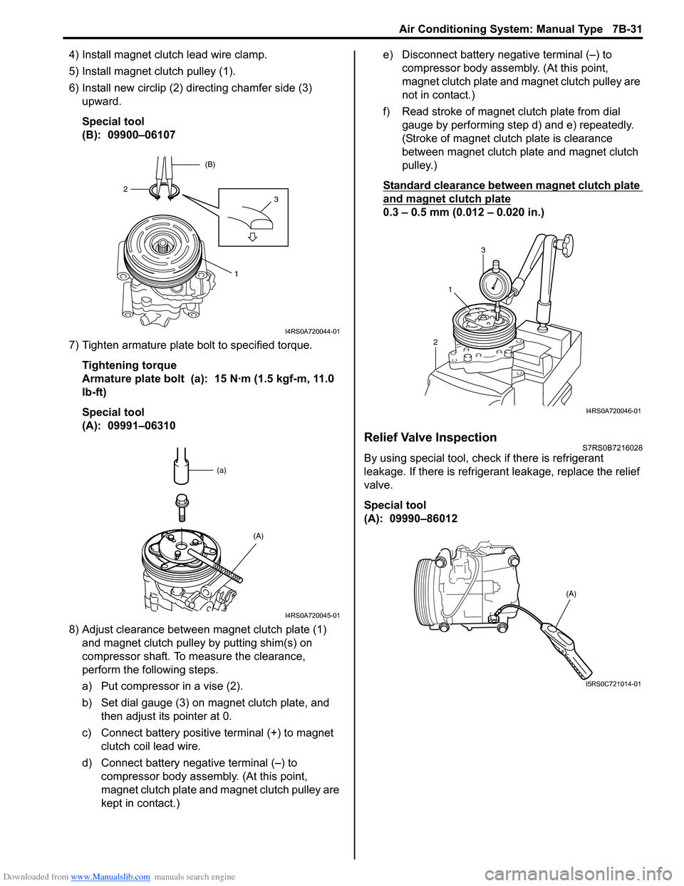
4) Install magnet clutch lead wire clamp.
5) Install magnet clutch pulley (1).
6) Install new circlip (2) directing chamfer side (3) upward.
Special tool
(B): 09900–06107
7) Tighten armature plate bolt to specified torque. Tightening torque
Armature plate bolt (a): 15 N·m (1.5 kgf-m, 11.0
lb-ft)
Special tool
(A): 09991–06310
8) Adjust clearance between magnet clutch plate (1) and magnet clutch pulley by putting shim(s) on
compressor shaft. To measure the clearance,
perform the following steps.
a) Put compressor in a vise (2).
b) Set dial gauge (3) on magnet clutch plate, and then adjust its pointer at 0.
c) Connect battery positive terminal (+) to magnet clutch coil lead wire.
d) Connect battery negative terminal (–) to compressor body assemb ly. (At this point,
magnet clutch plate and magnet clutch pulley are
kept in contact.) e) Disconnect battery negative terminal (–) to
compressor body assembly. (At this point,
magnet clutch plate and magnet clutch pulley are
not in contact.)
f) Read stroke of magnet clutch plate from dial gauge by performing step d) and e) repeatedly.
(Stroke of magnet clutch plate is clearance
between magnet clutch plate and magnet clutch
pulley.)
Standard clearance between magnet clutch plate
and magnet clutch plate
0.3 – 0.5 mm (0.012 – 0.020 in.)
Relief Valve InspectionS7RS0B7216028
By using special tool, chec k if there is refrigerant
leakage. If there is refrigerant leakage, replace the relief
valve.
Special tool
(A): 09990–86012
1
32 (B)
I4RS0A720044-01
(a)
(A)
I4RS0A720045-01
21
3
I4RS0A720046-01
(A)
I5RS0C721014-01