low SUZUKI SWIFT 2007 2.G Service Workshop Manual
[x] Cancel search | Manufacturer: SUZUKI, Model Year: 2007, Model line: SWIFT, Model: SUZUKI SWIFT 2007 2.GPages: 1496, PDF Size: 34.44 MB
Page 347 of 1496
Downloaded from www.Manualslib.com manuals search engine Engine Mechanical: 1D-62
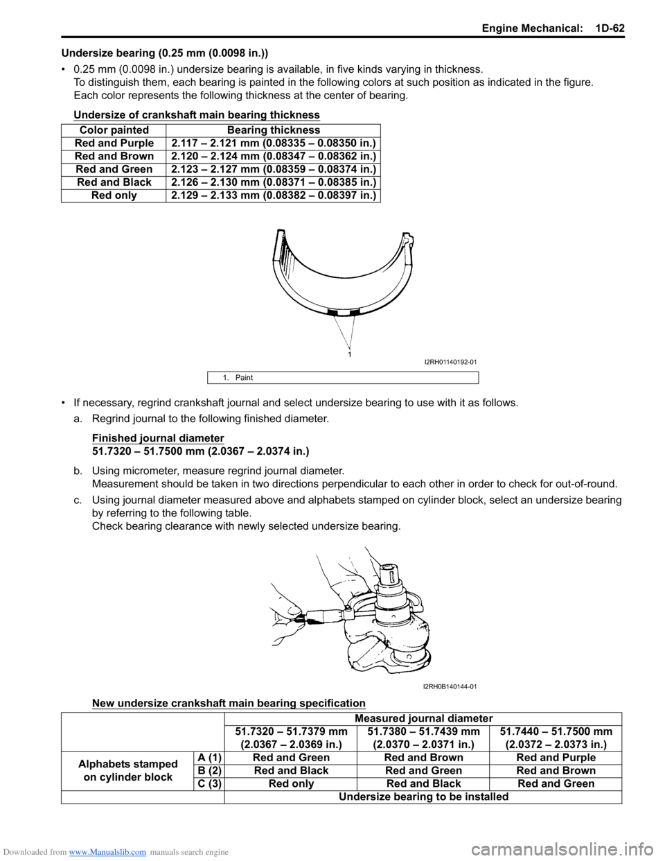
Undersize bearing (0.25 mm (0.0098 in.))
• 0.25 mm (0.0098 in.) undersize bearing is available, in five kinds varying in thickness.
To distinguish them, each bearing is painted in the following colors at such position as indicated in the figure.
Each color represents the following thickness at the center of bearing.
Undersize of crankshaft main bearing thickness
• If necessary, regrind crankshaft journal and sele ct undersize bearing to use with it as follows.
a. Regrind journal to the following finished diameter.
Finished journal diameter
51.7320 – 51.7500 mm (2.0367 – 2.0374 in.)
b. Using micrometer, measure regrind journal diameter. Measurement should be taken in two directions perpendicular to each other in order to check for out-of-round.
c. Using journal diameter measured above and alphabets stamped on cylinder block, select an undersize bearing
by referring to the following table.
Check bearing clearance with ne wly selected undersize bearing.
New undersize crankshaft main bearing specification
Color painted Bearing thickness
Red and Purple 2.117 – 2.121 mm (0.08335 – 0.08350 in.)
Red and Brown 2.120 – 2.124 mm (0.08347 – 0.08362 in.) Red and Green 2.123 – 2.127 mm (0.08359 – 0.08374 in.) Red and Black 2.126 – 2.130 mm (0.08371 – 0.08385 in.) Red only 2.129 – 2.133 mm (0.08382 – 0.08397 in.)
1. Paint
Measured journal diameter
51.7320 – 51.7379 mm (2.0367 – 2.0369 in.) 51.7380 – 51.7439 mm
(2.0370 – 2.0371 in.) 51.7440 – 51.7500 mm
(2.0372 – 2.0373 in.)
Alphabets stamped on cylinder block A (1) Red and Green Red and Brown Red and Purple
B (2) Red and Black Red and Green Red and Brown
C (3) Red only Red and Black Red and Green
Undersize bearing to be installed
I2RH01140192-01
I2RH0B140144-01
Page 349 of 1496
Downloaded from www.Manualslib.com manuals search engine Engine Mechanical: 1D-64
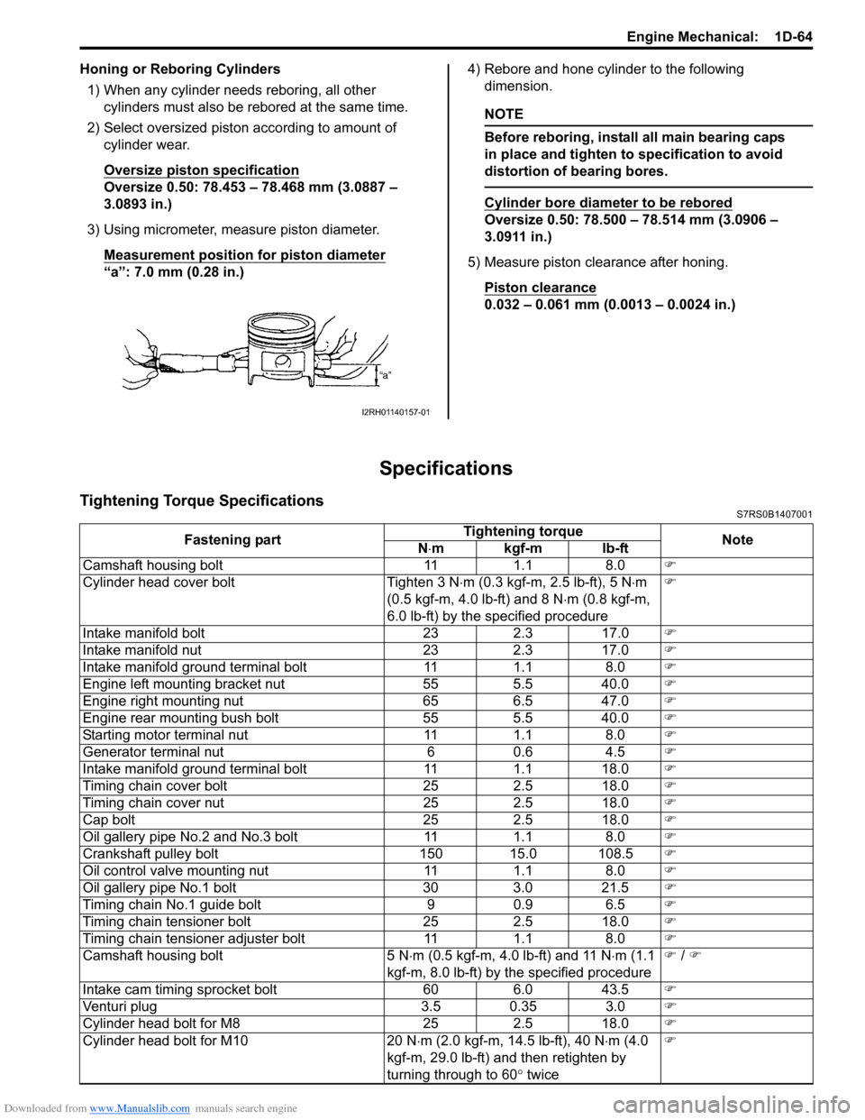
Honing or Reboring Cylinders1) When any cylinder needs reboring, all other cylinders must also be rebored at the same time.
2) Select oversized piston according to amount of cylinder wear.
Oversize piston specification
Oversize 0.50: 78.453 – 78.468 mm (3.0887 –
3.0893 in.)
3) Using micrometer, measure piston diameter. Measurement position for piston diameter
“a”: 7.0 mm (0.28 in.) 4) Rebore and hone cylinder to the following
dimension.
NOTE
Before reboring, install all main bearing caps
in place and tighten to specification to avoid
distortion of bearing bores.
Cylinder bore diameter to be rebored
Oversize 0.50: 78.500 – 78.514 mm (3.0906 –
3.0911 in.)
5) Measure piston clearance after honing. Piston clearance
0.032 – 0.061 mm (0.0013 – 0.0024 in.)
Specifications
Tightening Torque SpecificationsS7RS0B1407001
I2RH01140157-01
Fastening part Tightening torque
Note
N ⋅mkgf-mlb-ft
Camshaft housing bolt 11 1.1 8.0 )
Cylinder head cover bolt Tighten 3 N ⋅m (0.3 kgf-m, 2.5 lb-ft), 5 N ⋅m
(0.5 kgf-m, 4.0 lb-ft) and 8 N ⋅m (0.8 kgf-m,
6.0 lb-ft) by the specified procedure )
Intake manifold bolt 23 2.3 17.0 )
Intake manifold nut 23 2.3 17.0 )
Intake manifold ground terminal bolt 11 1.1 8.0 )
Engine left mounting bracket nut 55 5.5 40.0 )
Engine right mounting nut 65 6.5 47.0 )
Engine rear mounting bush bolt 55 5.5 40.0 )
Starting motor terminal nut 11 1.1 8.0 )
Generator terminal nut 6 0.6 4.5 )
Intake manifold ground terminal bolt 11 1.1 18.0 )
Timing chain cover bolt 25 2.5 18.0 )
Timing chain cover nut 25 2.5 18.0 )
Cap bolt 25 2.5 18.0 )
Oil gallery pipe No.2 and No.3 bolt 11 1.1 8.0 )
Crankshaft pulley bolt 150 15.0 108.5 )
Oil control valve mounting nut 11 1.1 8.0 )
Oil gallery pipe No.1 bolt 30 3.0 21.5 )
Timing chain No.1 guide bolt 9 0.9 6.5 )
Timing chain tensioner bolt 25 2.5 18.0 )
Timing chain tensioner adjuster bolt 11 1.1 8.0 )
Camshaft housing bolt 5 N ⋅m (0.5 kgf-m, 4.0 lb-ft) and 11 N ⋅m (1.1
kgf-m, 8.0 lb-ft) by the specified procedure )
/ )
Intake cam timing sprocket bolt 60 6.0 43.5 )
Venturi plug 3.5 0.35 3.0 )
Cylinder head bolt for M8 25 2.5 18.0 )
Cylinder head bolt for M10 20 N ⋅m (2.0 kgf-m, 14.5 lb-ft), 40 N ⋅m (4.0
kgf-m, 29.0 lb-ft) and then retighten by
turning through to 60 ° twice )
Page 350 of 1496
Downloaded from www.Manualslib.com manuals search engine 1D-65 Engine Mechanical:
NOTE
The specified tightening torque is also described in the following.
“Air Cleaner Components”
“Throttle Body and Intake Manifold Components”
“Engine Mountings Components”
“Timing Chain Cover Components”
“Timing Chain and Chain Tensioner Components”
“Camshaft, Tappet and Shim Components”
“Valves and Cylinder Head Components”
“Pistons, Piston Rings, Connecting Rods and Cylinders Components”
“Main Bearings, Crankshaft and Cylinder Block Components”
Reference:
For the tightening torque of fastener not specified in this section, refer to “Fasteners Information in Section 0A”.
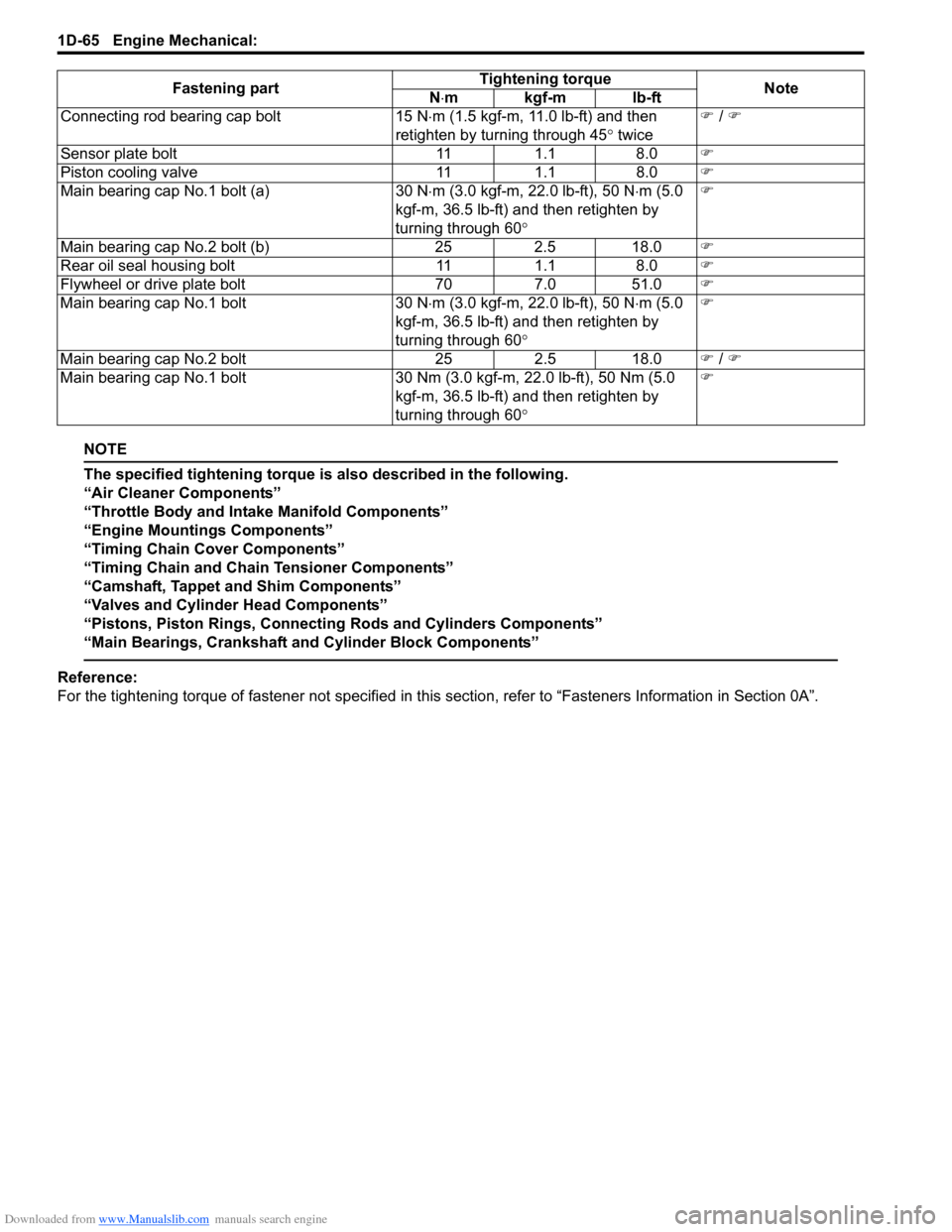
Connecting rod bearing cap bolt
15 N⋅m (1.5 kgf-m, 11.0 lb-ft) and then
retighten by turning through 45 ° twice )
/ )
Sensor plate bolt 111.1 8.0 )
Piston cooling valve 111.1 8.0 )
Main bearing cap No.1 bolt (a) 30 N⋅m (3.0 kgf-m, 22.0 lb-ft), 50 N ⋅m (5.0
kgf-m, 36.5 lb-ft) and then retighten by
turning through 60 ° )
Main bearing cap No.2 bolt (b) 252.5 18.0 )
Rear oil seal housing bolt 111.1 8.0 )
Flywheel or drive plate bolt 707.0 51.0 )
Main bearing cap No.1 bolt 30 N⋅m (3.0 kgf-m, 22.0 lb-ft), 50 N ⋅m (5.0
kgf-m, 36.5 lb-ft) and then retighten by
turning through 60 ° )
Main bearing cap No.2 bolt 252.5 18.0 ) / )
Main bearing cap No.1 bolt 30 Nm (3.0 kgf-m, 22.0 lb-ft), 50 Nm (5.0
kgf-m, 36.5 lb-ft) and then retighten by
turning through 60 ° )
Fastening part
Tightening torque
Note
N ⋅mkgf-mlb-ft
Page 351 of 1496
Downloaded from www.Manualslib.com manuals search engine Engine Mechanical: 1D-66
Special Tools and Equipment
Recommended Service MaterialS7RS0B1408001
NOTE
Required service material is also described in the following.
“Timing Chain Cover Components”
“Timing Chain and Chain Tensioner Components”
“Camshaft, Tappet and Shim Components”
“Valves and Cylinder Head Components”
“Pistons, Piston Rings, Connecting Rods and Cylinders Components”
“Main Bearings, Crankshaft and Cylinder Block Components”
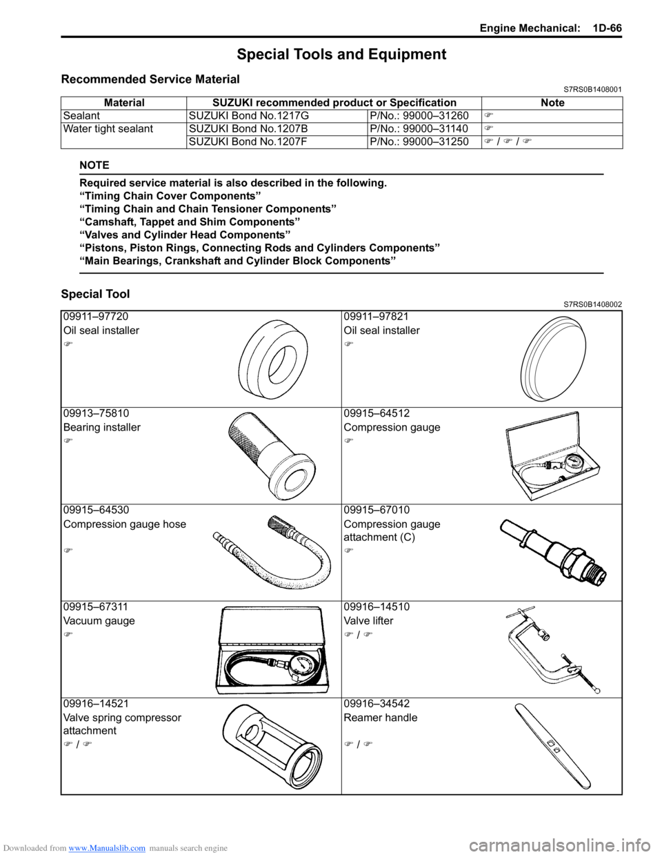
Special ToolS7RS0B1408002
Material SUZUKI recommended product or Specification Note
Sealant SUZUKI Bond No.1217G P/No.: 99000–31260)
Water tight sealant SUZUKI Bond No.1207B P/No.: 99000–31140)
SUZUKI Bond No.1207F P/No.: 99000–31250) / ) / )
09911–97720 09911–97821
Oil seal installer Oil seal installer
))
09913–75810 09915–64512
Bearing installer Compression gauge
))
09915–64530 09915–67010
Compression gauge hose Compression gauge
attachment (C)
))
09915–67311 09916–14510
Vacuum gauge Valve lifter
)) / )
09916–14521 09916–34542
Valve spring compressor
attachment Reamer handle
) / )) / )
Page 353 of 1496
Downloaded from www.Manualslib.com manuals search engine Engine Lubrication System: 1E-1
Engine
Engine Lubrication System
General Description
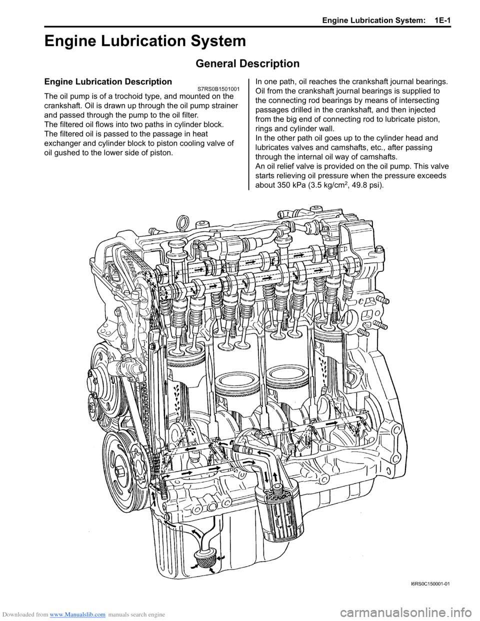
Engine Lubrication DescriptionS7RS0B1501001
The oil pump is of a trochoid type, and mounted on the
crankshaft. Oil is drawn up through the oil pump strainer
and passed through the pump to the oil filter.
The filtered oil flows into two paths in cylinder block.
The filtered oil is passed to the passage in heat
exchanger and cylinder block to piston cooling valve of
oil gushed to the lower side of piston. In one path, oil reaches the crankshaft journal bearings.
Oil from the crankshaft journal bearings is supplied to
the connecting rod bearings by means of intersecting
passages drilled in the cran
kshaft, and then injected
from the big end of connecting rod to lubricate piston,
rings and cylinder wall.
In the other path oil goes up to the cylinder head and
lubricates valves and camshafts, etc., after passing
through the internal oil way of camshafts.
An oil relief valve is provided on the oil pump. This valve
starts relieving oil pressure when the pressure exceeds
about 350 kPa (3.5 kg/cm
2, 49.8 psi).
I6RS0C150001-01
Page 354 of 1496
Downloaded from www.Manualslib.com manuals search engine 1E-2 Engine Lubrication System:
Diagnostic Information and Procedures
Oil Pressure CheckS7RS0B1504001
WARNING!
To avoid danger of being burned, do not
touch exhaust system when it is still hot.
NOTE
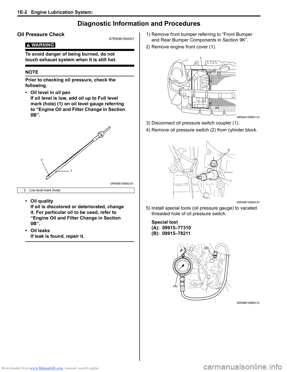
Prior to checking oil pressure, check the
following.
• Oil level in oil pan
If oil level is low, add oil up to Full level
mark (hole) (1) on oil level gauge referring
to “Engine Oil and Filter Change in Section
0B”.
• Oil quality If oil is discolored or deteriorated, change
it. For particular oil to be used, refer to
“Engine Oil and Filter Change in Section
0B”.
• Oil leaks If leak is found, repair it.
1) Remove front bumper referring to “Front Bumper and Rear Bumper Components in Section 9K”.
2) Remove engine front cover (1).
3) Disconnect oil pressure switch coupler (1).
4) Remove oil pressure swit ch (2) from cylinder block.
5) Install special tools (oil pressure gauge) to vacated threaded hole of oil pressure switch.
Special tool
(A): 09915–77310
(B): 09915–78211
2. Low level mark (hole)
I2RH0B150002-01
1
I4RS0A150001-01
I2RH0B150003-01
I2RH0B150004-01
Page 356 of 1496
Downloaded from www.Manualslib.com manuals search engine 1E-4 Engine Lubrication System:
Heat Exchanger On-Vehicle InspectionS7RS0B1506002
• Check heat exchanger for deformation wear or damage.
• Check heat exchanger for coolant leakage and oil leakage.
If any malcondition is found, replace O-ring, stand bolt
gasket and/or heat exchanger.
Heat Exchanger Removal and InstallationS7RS0B1506003
Removal
1) Drain engine oil by removing drain plug.
2) Drain coolant referring to “Cooling System Draining in Section 1F”.
3) Remove exhaust manifold referring to “Exhaust Manifold Removal and Inst allation in Section 1K”.
4) Remove heat exchanger inlet No. 1 hose and outlet No. 1 hose.
5) Remove heat exchanger, O-ring and gasket by removing heat exchanger stand bolt. Installation
Reverse removal procedure for installation noting the
followings.
• Use new stand bolt gasket.
• Apply engine oil to new O-ring and install it to heat
exchanger.
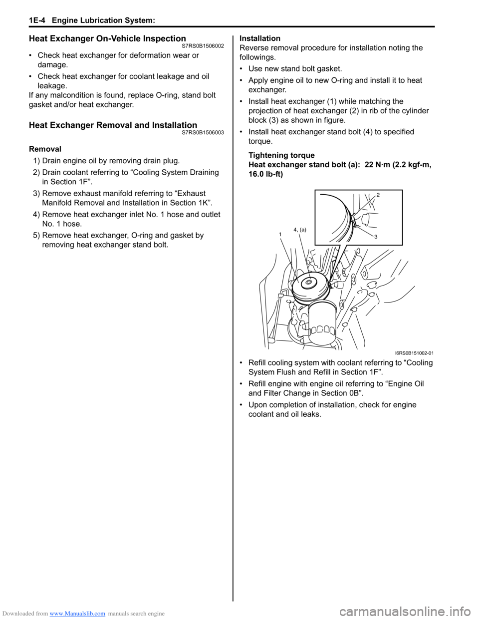
• Install heat exchanger (1) while matching the projection of heat exchanger (2) in rib of the cylinder
block (3) as shown in figure.
• Install heat exchanger stand bolt (4) to specified torque.
Tightening torque
Heat exchanger stand bolt (a): 22 N·m (2.2 kgf-m,
16.0 lb-ft)
• Refill cooling system with co olant referring to “Cooling
System Flush and Refill in Section 1F”.
• Refill engine with engine oil referring to “Engine Oil and Filter Change in Section 0B”.
• Upon completion of installation, check for engine coolant and oil leaks.
2
3
4, (a)
1
I6RS0B151002-01
Page 357 of 1496
Downloaded from www.Manualslib.com manuals search engine Engine Lubrication System: 1E-5
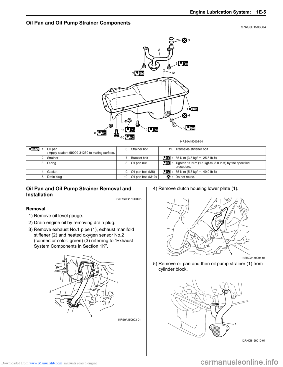
Oil Pan and Oil Pump Strainer ComponentsS7RS0B1506004
Oil Pan and Oil Pump Strainer Removal and
Installation
S7RS0B1506005
Removal1) Remove oil level gauge.
2) Drain engine oil by removing drain plug.
3) Remove exhaust No.1 pipe (1), exhaust manifold stiffener (2) and heated oxygen sensor No.2
(connector color: green) (3) referring to “Exhaust
System Components in Section 1K”. 4) Remove clutch housing lower plate (1).
5) Remove oil pan and then oil pump strainer (1) from
cylinder block.
I4RS0A150002-01
1. Oil pan : Apply sealant 99000-31260 to mating surface. 6. Strainer bolt 11. Transaxle stiffener bolt
2. Strainer 7. Bracket bolt : 35 N ⋅m (3.5 kgf-m, 25.5 lb-ft)
3. O-ring 8. Oil pan nut : Tighten 11 N ⋅m (1.1 kgf-m, 8.0 lb-ft) by the specified
procedure.
4. Gasket 9. Oil pan bolt (M6) : 55 N ⋅m (5.5 kgf-m, 40.0 lb-ft)
5. Drain plug 10. Oil pan bolt (M10) : Do not reuse.
2
1
3
I4RS0A150003-01
1I4RS0A150004-01
I2RH0B150010-01
Page 359 of 1496
Downloaded from www.Manualslib.com manuals search engine Engine Lubrication System: 1E-7
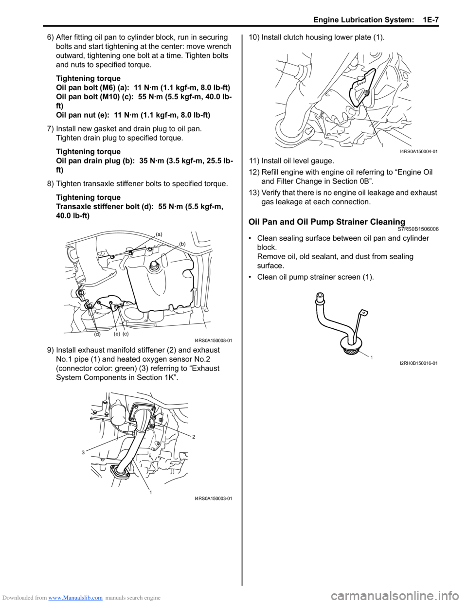
6) After fitting oil pan to cylinder block, run in securing bolts and start tightening at the center: move wrench
outward, tightening one bolt at a time. Tighten bolts
and nuts to specified torque.
Tightening torque
Oil pan bolt (M6) (a): 11 N·m (1.1 kgf-m, 8.0 lb-ft)
Oil pan bolt (M10) (c): 55 N·m (5.5 kgf-m, 40.0 lb-
ft)
Oil pan nut (e): 11 N·m (1.1 kgf-m, 8.0 lb-ft)
7) Install new gasket and drain plug to oil pan. Tighten drain plug to specified torque.
Tightening torque
Oil pan drain plug (b): 35 N·m (3.5 kgf-m, 25.5 lb-
ft)
8) Tighten transaxle stiffener bolts to specified torque. Tightening torque
Transaxle stiffener bolt (d): 55 N·m (5.5 kgf-m,
40.0 lb-ft)
9) Install exhaust manifold stiffener (2) and exhaust No.1 pipe (1) and heated oxygen sensor No.2
(connector color: green) (3) referring to “Exhaust
System Components in Section 1K”. 10) Install clutch housing lower plate (1).
11) Install oil level gauge.
12) Refill engine with engine oil referring to “Engine Oil
and Filter Change in Section 0B”.
13) Verify that there is no en gine oil leakage and exhaust
gas leakage at each connection.
Oil Pan and Oil Pump Strainer CleaningS7RS0B1506006
• Clean sealing surface between oil pan and cylinder block.
Remove oil, old sealant, and dust from sealing
surface.
• Clean oil pump strainer screen (1).(a)
(b)
(c)(e)
(d)I4RS0A150008-01
2
1
3
I4RS0A150003-01
1I4RS0A150004-01
I2RH0B150016-01
Page 361 of 1496
Downloaded from www.Manualslib.com manuals search engine Engine Lubrication System: 1E-9
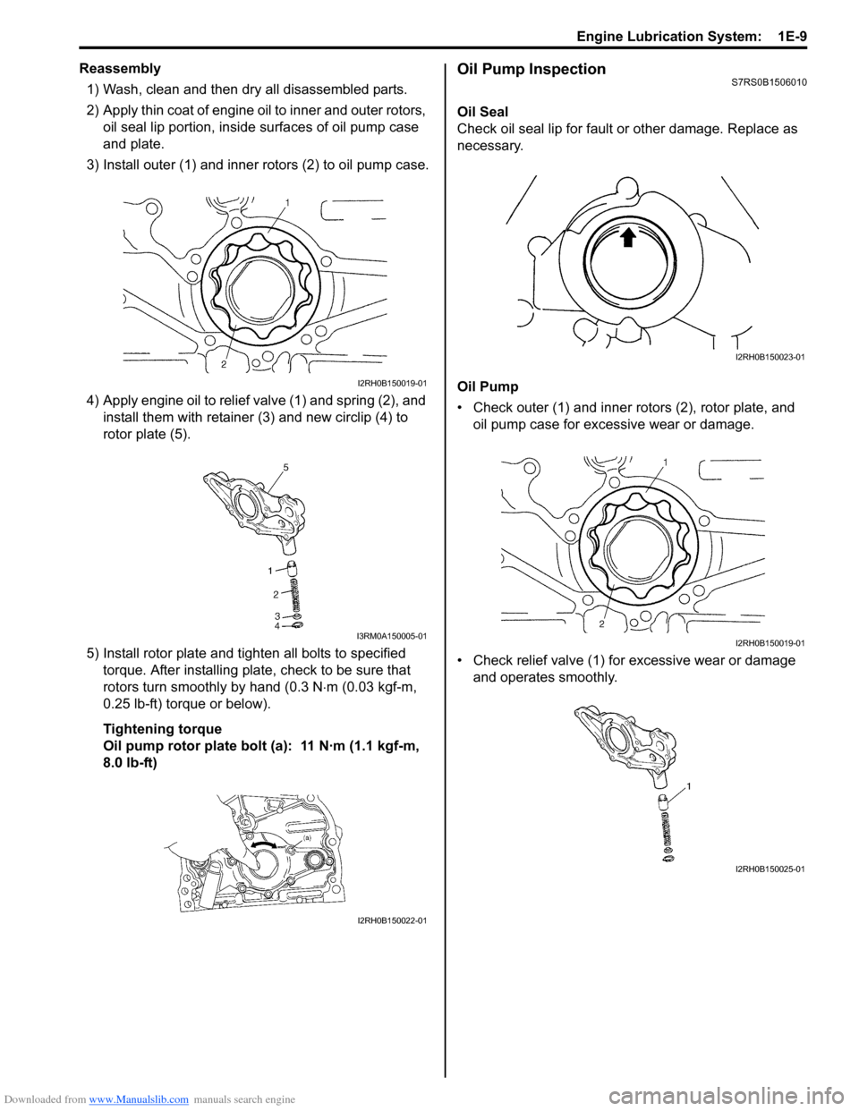
Reassembly1) Wash, clean and then dry all disassembled parts.
2) Apply thin coat of engine oil to inner and outer rotors, oil seal lip portion, inside surfaces of oil pump case
and plate.
3) Install outer (1) and inner rotors (2) to oil pump case.
4) Apply engine oil to relief valve (1) and spring (2), and install them with retainer (3) and new circlip (4) to
rotor plate (5).
5) Install rotor plate and tighten all bolts to specified torque. After installing plate, check to be sure that
rotors turn smoothly by hand (0.3 N ⋅m (0.03 kgf-m,
0.25 lb-ft) torque or below).
Tightening torque
Oil pump rotor plate bolt (a): 11 N·m (1.1 kgf-m,
8.0 lb-ft)Oil Pump InspectionS7RS0B1506010
Oil Seal
Check oil seal lip for fault or other damage. Replace as
necessary.
Oil Pump
• Check outer (1) and inner rotors (2), rotor plate, and oil pump case for excessive wear or damage.
• Check relief valve (1) for excessive wear or damage
and operates smoothly.
I2RH0B150019-01
I3RM0A150005-01
I2RH0B150022-01
I2RH0B150023-01
I2RH0B150019-01
I2RH0B150025-01