low SUZUKI SWIFT 2007 2.G Service Workshop Manual
[x] Cancel search | Manufacturer: SUZUKI, Model Year: 2007, Model line: SWIFT, Model: SUZUKI SWIFT 2007 2.GPages: 1496, PDF Size: 34.44 MB
Page 304 of 1496
Downloaded from www.Manualslib.com manuals search engine 1D-19 Engine Mechanical:
24) Before removing engine with transaxle from engine compartment, recheck to make sure all hoses,
electric wires and cables are disconnected from
engine and transaxle.
25) Lower engine with transaxle from engine compartment.
CAUTION!
Before lowering engine, to avoid damage to
A/C compressor and clutch operating
cylinder, make clearance by rising them. Be
sure not to damage suspended A/C
compressor and clutch operating cylinder.
26) Disconnect transaxle from engine, referring to “Manual Transaxle Unit Dismounting and
Remounting in Section 5B” or “Automatic Transaxle
Unit Dismounting and Re mounting in Section 5A”.
27) For M/T model, remove clutch cover and clutch disk referring to “Clutch Cover, Clutch Disc and Flywheel
Removal and Installa tion in Section 5C”.
Installation 1) For M/T model, install clutch cover and clutch disk referring to “Clutch Cover, Clutch Disc and Flywheel
Removal and Installa tion in Section 5C”.
2) Connect transaxle to engine referring to “Manual Transaxle Unit Dismounting and Remounting in
Section 5B” or “Automatic Transaxle Unit
Dismounting and Remounting in Section 5A”.
3) Lift engine and transaxle into engine compartment with jack.
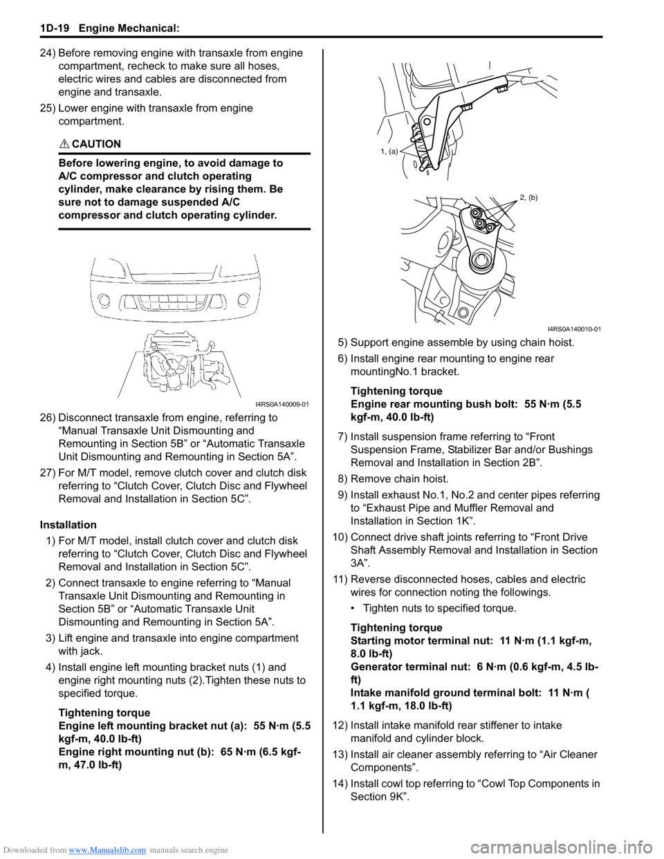
4) Install engine left mounting bracket nuts (1) and engine right mounting nuts (2).Tighten these nuts to
specified torque.
Tightening torque
Engine left mounting bracket nut (a): 55 N·m (5.5
kgf-m, 40.0 lb-ft)
Engine right mounting nut (b): 65 N·m (6.5 kgf-
m, 47.0 lb-ft) 5) Support engine assemble by using chain hoist.
6) Install engine rear mounting to engine rear
mountingNo.1 bracket.
Tightening torque
Engine rear mounting bush bolt: 55 N·m (5.5
kgf-m, 40.0 lb-ft)
7) Install suspension frame referring to “Front Suspension Frame, Stabiliz er Bar and/or Bushings
Removal and Installati on in Section 2B”.
8) Remove chain hoist.
9) Install exhaust No.1, No.2 and center pipes referring to “Exhaust Pipe and Muffler Removal and
Installation in Section 1K”.
10) Connect drive shaft joints referring to “Front Drive Shaft Assembly Removal and Installation in Section
3A”.
11) Reverse disconnected hoses, cables and electric wires for connection noting the followings.
• Tighten nuts to specified torque.
Tightening torque
Starting motor terminal nut: 11 N·m (1.1 kgf-m,
8.0 lb-ft)
Generator terminal nut: 6 N·m (0.6 kgf-m, 4.5 lb-
ft)
Intake manifold ground terminal bolt: 11 N·m (
1.1 kgf-m, 18.0 lb-ft)
12) Install intake manifold rear stiffener to intake
manifold and cylinder block.
13) Install air cleaner assembly referring to “Air Cleaner Components”.
14) Install cowl top referring to “Cowl Top Components in
Section 9K”.
I4RS0A140009-01
1, (a)
2, (b)
I4RS0A140010-01
Page 310 of 1496
Downloaded from www.Manualslib.com manuals search engine 1D-25 Engine Mechanical:
Timing Chain and Chain Tensioner Removal
and Installation
S7RS0B1406018
Removal
CAUTION!
After timing chain is removed, never turn
crankshaft and camshafts independently
more than its allowable turning range
described in “Installation”.
If turned, interferen ce may occur between
piston and valves and valves themselves,
and parts related to piston and valves may be
damaged.
1) Remove timing chain cover referring to “Timing Chain Cover Removal and Installation”.
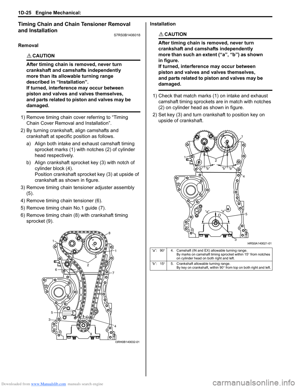
2) By turning crankshaft, align camshafts and crankshaft at specific position as follows.
a) Align both intake and exhaust camshaft timing sprocket marks (1) with notches (2) of cylinder
head respectively.
b) Align crankshaft sprocket key (3) with notch of cylinder block (4).
Position crankshaft sprocke t key (3) at upside of
crankshaft as shown in figure.
3) Remove timing chain tensioner adjuster assembly (5).
4) Remove timing chain tensioner (6).
5) Remove timing chain No.1 guide (7).
6) Remove timing chain (8) with crankshaft timing sprocket (9). Installation
CAUTION!
After timing chain is removed, never turn
crankshaft and camshafts independently
more than such an extent (“a”, “b”) as shown
in figure.
If turned, interferen
ce may occur between
piston and valves and valves themselves,
and parts related to piston and valves may be
damaged.
1) Check that match marks (1) on intake and exhaust camshaft timing sprockets are in match with notches
(2) on cylinder head as shown in figure.
2) Set key (3) and turn crankshaft to position key on upside of crankshaft.
3
4
1
1
2
5
67
8
9
I3RH0B140032-01
“a”: 90 °4. Camshaft (IN and EX) allowable turning range.
By marks on camshaft timing sprocket within 15 ° from notches
on cylinder head on both right and left.
“b”: 15 °5. Crankshaft allowable turning range.
By key on crankshaft, within 90 ° from top on both right and left.
“a”
“b”
“b”“b”
“b”
“a”
1
12
4
3
5
I4RS0A140021-01
Page 312 of 1496
Downloaded from www.Manualslib.com manuals search engine 1D-27 Engine Mechanical:
8) Screw in plunger (1) by turning body (2) in arrow direction and install a reta iner (3) (wire) to hold
plunger in place.
9) Install timing chain tensioner adjuster assembly (1) with a retainer (2).
Tighten adjuster bolts to specified torque and then
remove a retainer from chain tensioner adjuster
assembly.
Tightening torque
Timing chain tensioner adjuster bolt (a): 11 N·m
(1.1 kgf-m, 8.0 lb-ft)
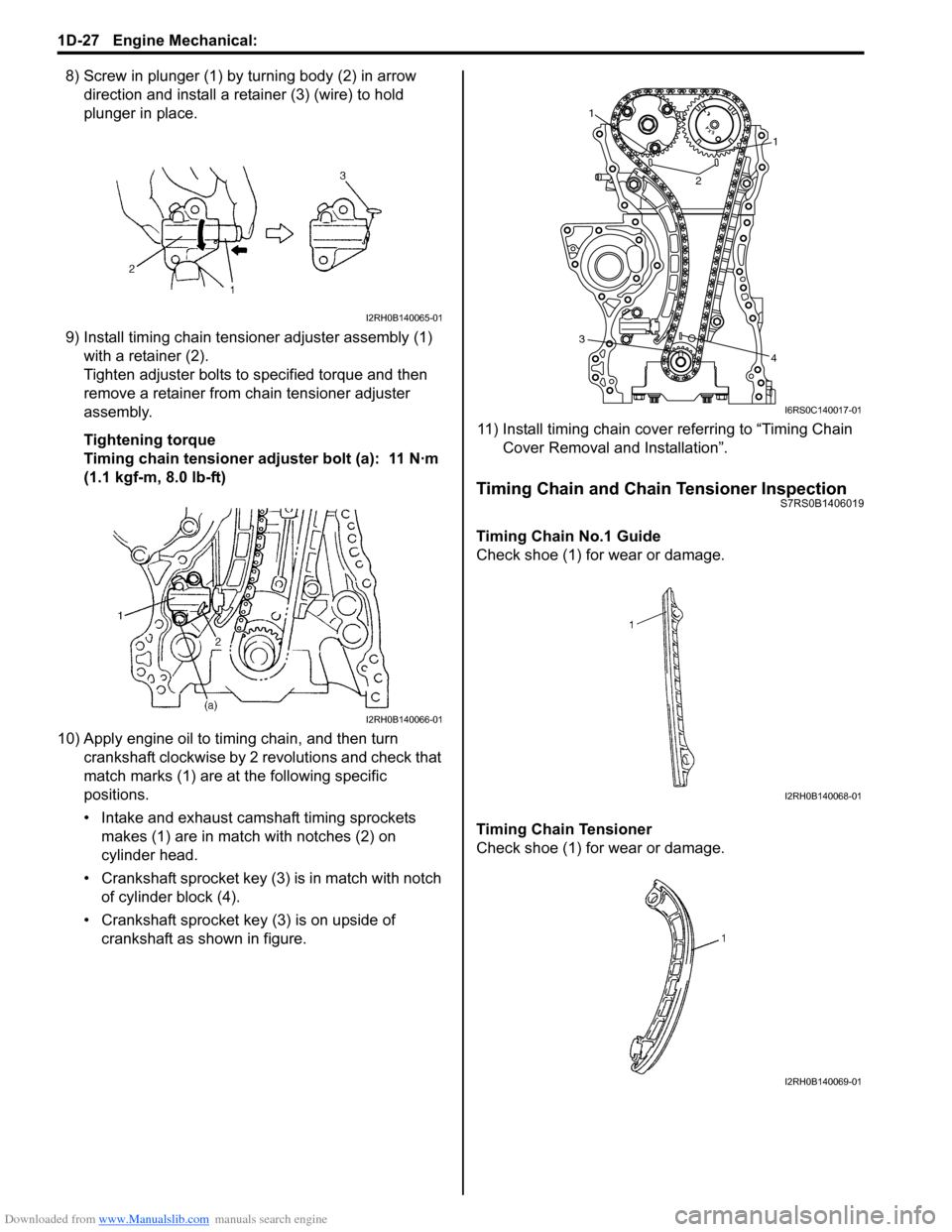
10) Apply engine oil to timing chain, and then turn crankshaft clockwise by 2 revolutions and check that
match marks (1) are at the following specific
positions.
• Intake and exhaust camshaft timing sprockets makes (1) are in match with notches (2) on
cylinder head.
• Crankshaft sprocket key (3) is in match with notch of cylinder block (4).
• Crankshaft sprocket key (3) is on upside of crankshaft as shown in figure. 11) Install timing chain cover referring to “Timing Chain
Cover Removal and Installation”.
Timing Chain and Chain Tensioner InspectionS7RS0B1406019
Timing Chain No.1 Guide
Check shoe (1) for wear or damage.
Timing Chain Tensioner
Check shoe (1) for wear or damage.
I2RH0B140065-01
I2RH0B140066-01
1
1
2
3 4
I6RS0C140017-01
I2RH0B140068-01
I2RH0B140069-01
Page 314 of 1496
Downloaded from www.Manualslib.com manuals search engine 1D-29 Engine Mechanical:
Camshaft, Tappet and Shim Removal and
Installation
S7RS0B1406021
CAUTION!
• Keep working table, tools and hands clean while overhauling.
• Use special care to handle aluminum parts so as not to damage them.
• Do not expose removed parts to dust. Keep them always clean.
Removal
1) Remove timing chain cover referring to “Timing Chain Cover Removal and Installation”.
2) Remove timing chain referring to “Timing Chain and Chain Tensioner Removal and Installation”.
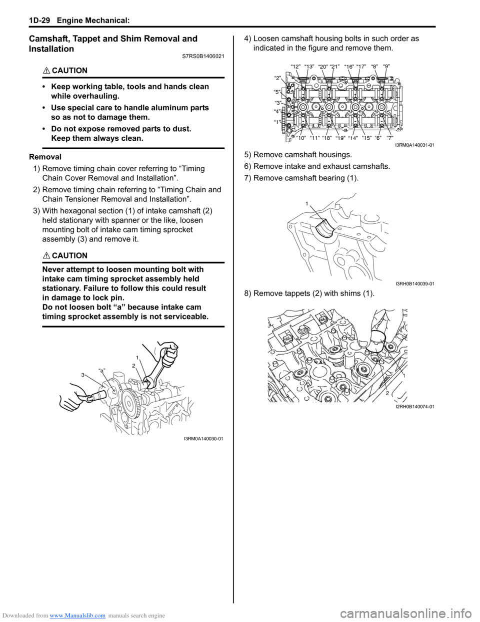
3) With hexagonal section (1) of intake camshaft (2) held stationary with spanner or the like, loosen
mounting bolt of intake cam timing sprocket
assembly (3) and remove it.
CAUTION!
Never attempt to loosen mounting bolt with
intake cam timing sprocket assembly held
stationary. Failure to fo llow this could result
in damage to lock pin.
Do not loosen bolt “a” because intake cam
timing sprocket assembly is not serviceable.
4) Loosen camshaft housing bolts in such order as indicated in the figure and remove them.
5) Remove camshaft housings.
6) Remove intake and exhaust camshafts.
7) Remove camshaft bearing (1).
8) Remove tappets (2) with shims (1).
3“a”
1
2
I3RM0A140030-01
“12”“13” “20”“21”
“16”“17” “8” “9”
“2”
“5” “3”
“4”
“1”
“10”“11”“18”
“19” “14” “15” “6” “7”
I3RM0A140031-01
1
I3RH0B140039-01
I2RH0B140074-01
Page 316 of 1496
Downloaded from www.Manualslib.com manuals search engine 1D-31 Engine Mechanical:
7) Install camshaft housing.
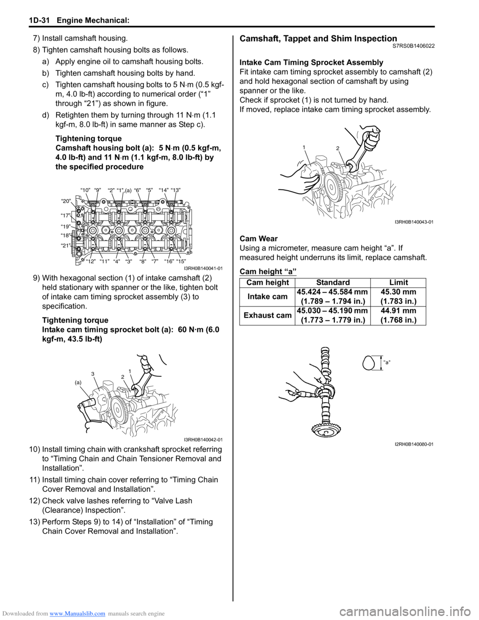
8) Tighten camshaft housing bolts as follows.a) Apply engine oil to camshaft housing bolts.
b) Tighten camshaft housing bolts by hand.
c) Tighten camshaft housing bolts to 5 N ⋅m (0.5 kgf-
m, 4.0 lb-ft) according to numerical order (“1”
through “21”) as shown in figure.
d) Retighten them by turning through 11 N⋅ m (1.1
kgf-m, 8.0 lb-ft) in same manner as Step c).
Tightening torque
Camshaft housing bolt (a): 5 N ⋅m (0.5 kgf-m,
4.0 lb-ft) and 11 N ⋅m (1.1 kgf-m, 8.0 lb-ft) by
the specified procedure
9) With hexagonal section (1) of intake camshaft (2) held stationary with spanner or the like, tighten bolt
of intake cam timing sp rocket assembly (3) to
specification.
Tightening torque
Intake cam timing sprocket bolt (a): 60 N·m (6.0
kgf-m, 43.5 lb-ft)
10) Install timing chain with cr ankshaft sprocket referring
to “Timing Chain and Chain Tensioner Removal and
Installation”.
11) Install timing chain cover referring to “Timing Chain Cover Removal and Installation”.
12) Check valve lashes referring to “Valve Lash (Clearance) Inspection”.
13) Perform Steps 9) to 14) of “Installation” of “Timing Chain Cover Removal and Installation”.Camshaft, Tappet and Shim InspectionS7RS0B1406022
Intake Cam Timing Sprocket Assembly
Fit intake cam timing sprocket assembly to camshaft (2)
and hold hexagonal section of camshaft by using
spanner or the like.
Check if sprocket (1) is not turned by hand.
If moved, replace intake ca m timing sprocket assembly.
Cam Wear
Using a micrometer, measure cam height “a”. If
measured height underruns its limit, replace camshaft.
Cam height “a”
“10”“9” “2” “1”,(a) “6” “5” “14” “13”
“20”
“17” “19”
“18”
“21”
“12”“11”
“4” “3” “8” “7” “16” “15”
I3RH0B140041-01
1
2
3
(a)
I3RH0B140042-01
Cam height Standard Limit
Intake cam 45.424 – 45.584 mm
(1.789 – 1.794 in.) 45.30 mm
(1.783 in.)
Exhaust cam 45.030 – 45.190 mm
(1.773 – 1.779 in.) 44.91 mm
(1.768 in.)
2
1
I3RH0B140043-01
I2RH0B140080-01
Page 317 of 1496
Downloaded from www.Manualslib.com manuals search engine Engine Mechanical: 1D-32
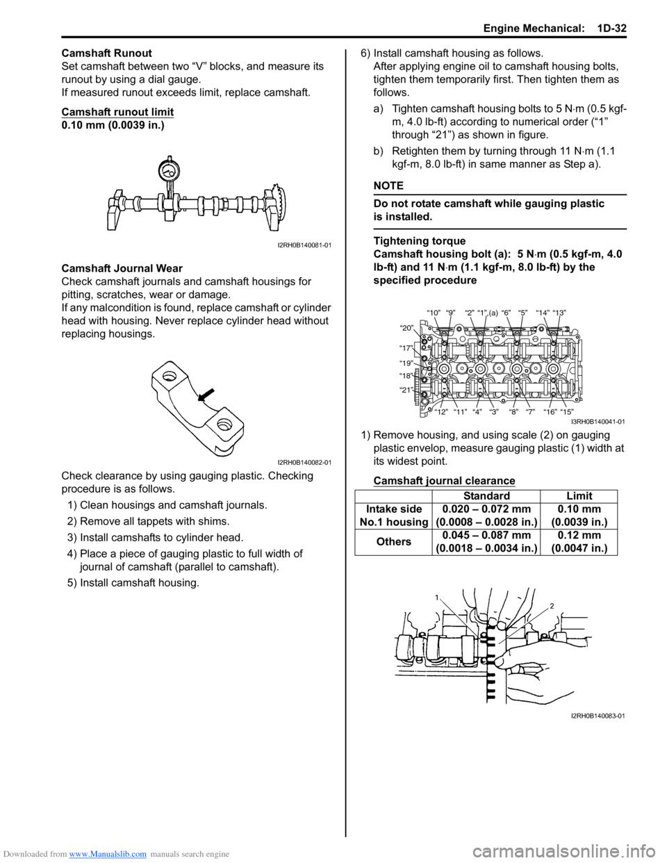
Camshaft Runout
Set camshaft between two “V” blocks, and measure its
runout by using a dial gauge.
If measured runout exceeds limit, replace camshaft.
Camshaft runout limit
0.10 mm (0.0039 in.)
Camshaft Journal Wear
Check camshaft journals and camshaft housings for
pitting, scratches, wear or damage.
If any malcondition is found, replace camshaft or cylinder
head with housing. Never re place cylinder head without
replacing housings.
Check clearance by using ga uging plastic. Checking
procedure is as follows.
1) Clean housings and camshaft journals.
2) Remove all tappets with shims.
3) Install camshafts to cylinder head.
4) Place a piece of gauging plastic to full width of
journal of camshaft (parallel to camshaft).
5) Install camshaft housing. 6) Install camshaft housing as follows.
After applying engine oil to camshaft housing bolts,
tighten them temporarily first. Then tighten them as
follows.
a) Tighten camshaft housing bolts to 5 N ⋅m (0.5 kgf-
m, 4.0 lb-ft) according to numerical order (“1”
through “21”) as shown in figure.
b) Retighten them by turning through 11 N ⋅m (1.1
kgf-m, 8.0 lb-ft) in same manner as Step a).
NOTE
Do not rotate camshaft while gauging plastic
is installed.
Tightening torque
Camshaft housing bolt (a): 5 N ⋅m (0.5 kgf-m, 4.0
lb-ft) and 11 N ⋅m (1.1 kgf-m, 8.0 lb-ft) by the
specified procedure
1) Remove housing, and using scale (2) on gauging plastic envelop, measure gauging plastic (1) width at
its widest point.
Camshaft journal clearanceI2RH0B140081-01
I2RH0B140082-01
Standard Limit
Intake side
No.1 housing 0.020 – 0.072 mm
(0.0008 – 0.0028 in.) 0.10 mm
(0.0039 in.)
Others 0.045 – 0.087 mm
(0.0018 – 0.0034 in.) 0.12 mm
(0.0047 in.)
“10”“9” “2” “1”,(a) “6” “5” “14” “13”
“20”
“17” “19”
“18”
“21”
“12”“11”
“4” “3” “8” “7” “16” “15”
I3RH0B140041-01
I2RH0B140083-01
Page 321 of 1496
Downloaded from www.Manualslib.com manuals search engine Engine Mechanical: 1D-36
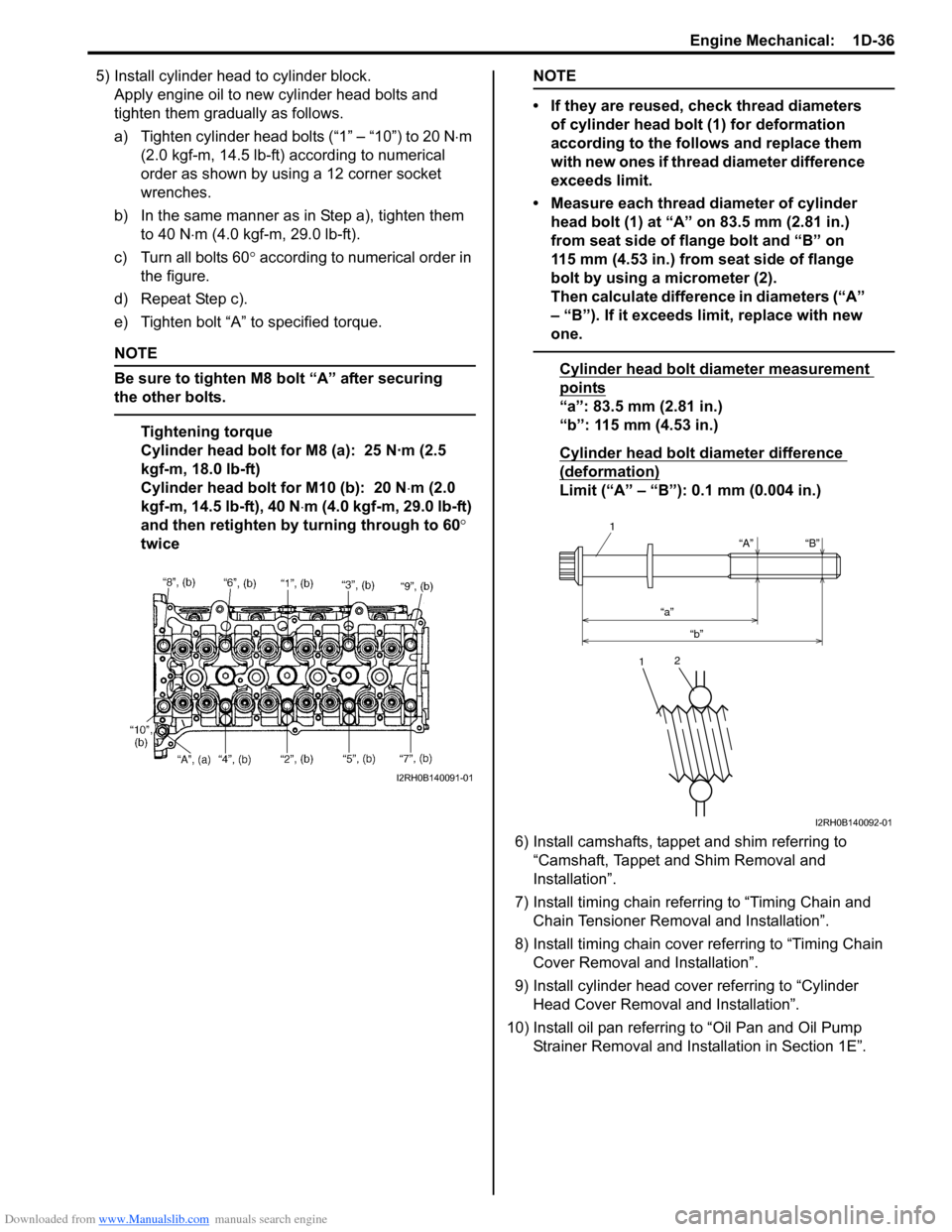
5) Install cylinder head to cylinder block.Apply engine oil to new cylinder head bolts and
tighten them gradually as follows.
a) Tighten cylinder head bolts (“1” – “10”) to 20 N ⋅m
(2.0 kgf-m, 14.5 lb-ft) according to numerical
order as shown by using a 12 corner socket
wrenches.
b) In the same manner as in Step a), tighten them to 40 N ⋅m (4.0 kgf-m, 29.0 lb-ft).
c) Turn all bolts 60 ° according to numerical order in
the figure.
d) Repeat Step c).
e) Tighten bolt “A” to specified torque.
NOTE
Be sure to tighten M8 bolt “A” after securing
the other bolts.
Tightening torque
Cylinder head bolt for M8 (a): 25 N·m (2.5
kgf-m, 18.0 lb-ft)
Cylinder head bolt for M10 (b): 20 N ⋅m (2.0
kgf-m, 14.5 lb-ft), 40 N ⋅m (4.0 kgf-m, 29.0 lb-ft)
and then retighten by turning through to 60 °
twice
NOTE
• If they are reused, check thread diameters of cylinder head bolt (1) for deformation
according to the follows and replace them
with new ones if thread diameter difference
exceeds limit.
• Measure each thread diameter of cylinder head bolt (1) at “A” on 83.5 mm (2.81 in.)
from seat side of flange bolt and “B” on
115 mm (4.53 in.) from seat side of flange
bolt by using a micrometer (2).
Then calculate difference in diameters (“A”
– “B”). If it exceeds limit, replace with new
one.
Cylinder head bolt diameter measurement
points
“a”: 83.5 mm (2.81 in.)
“b”: 115 mm (4.53 in.)
Cylinder head bolt diameter difference
(deformation)
Limit (“A” – “B”): 0.1 mm (0.004 in.)
6) Install camshafts, tappet and shim referring to “Camshaft, Tappet and Shim Removal and
Installation”.
7) Install timing chain referring to “Timing Chain and Chain Tensioner Remova l and Installation”.
8) Install timing chain cover referring to “Timing Chain Cover Removal and Installation”.
9) Install cylinder head cover referring to “Cylinder Head Cover Removal and Installation”.
10) Install oil pan referring to “Oil Pan and Oil Pump
Strainer Removal and Inst allation in Section 1E”.
I2RH0B140091-01
“A”
“a” “b” “B”
1
1
2
I2RH0B140092-01
Page 326 of 1496
Downloaded from www.Manualslib.com manuals search engine 1D-41 Engine Mechanical:
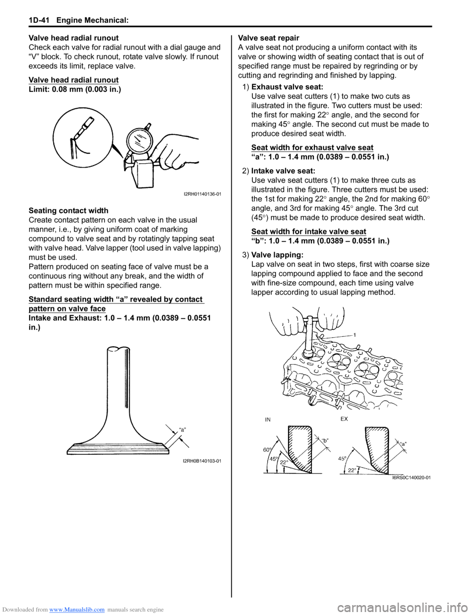
Valve head radial runout
Check each valve for radial runout with a dial gauge and
“V” block. To check runout, rotate valve slowly. If runout
exceeds its limit, replace valve.
Valve head radial runout
Limit: 0.08 mm (0.003 in.)
Seating contact width
Create contact pattern on each valve in the usual
manner, i.e., by giving uniform coat of marking
compound to valve seat and by rotatingly tapping seat
with valve head. Valve lapper (tool used in valve lapping)
must be used.
Pattern produced on seating face of valve must be a
continuous ring without any break, and the width of
pattern must be within specified range.
Standard seating width “a” revealed by contact
pattern on valve face
Intake and Exhaust: 1.0 – 1.4 mm (0.0389 – 0.0551
in.)Valve seat repair
A valve seat not producing
a uniform contact with its
valve or showing width of seating contact that is out of
specified range must be repaired by regrinding or by
cutting and regrinding and finished by lapping.
1) Exhaust valve seat:
Use valve seat cutters (1 ) to make two cuts as
illustrated in the figure. Two cutters must be used:
the first for making 22 ° angle, and the second for
making 45 ° angle. The second cut must be made to
produce desired seat width.
Seat width for exhaust valve seat
“a”: 1.0 – 1.4 mm (0.0389 – 0.0551 in.)
2) Intake valve seat:
Use valve seat cutters (1) to make three cuts as
illustrated in the figure. Th ree cutters must be used:
the 1st for making 22 ° angle, the 2nd for making 60 °
angle, and 3rd for making 45 ° angle. The 3rd cut
(45 °) must be made to produce desired seat width.
Seat width for intake valve seat
“b”: 1.0 – 1.4 mm (0.0389 – 0.0551 in.)
3) Valve lapping:
Lap valve on seat in two steps, first with coarse size
lapping compound applied to face and the second
with fine-size compound, each time using valve
lapper according to usual lapping method.
I2RH01140136-01
I2RH0B140103-01
I6RS0C140020-01
Page 330 of 1496
Downloaded from www.Manualslib.com manuals search engine 1D-45 Engine Mechanical:
Pistons, Piston Rings, Connecting Rods and
Cylinders Removal and Installation
S7RS0B1406030
Removal1) Remove engine assembly from vehicle referring to “Engine Assembly Removal and Installation”.
2) Remove cylinder head referring to “Valves and Cylinder Head Removal and Installation”.
3) Mark cylinder number on all pistons, connecting rods
and connecting rod caps using silver pencil or quick
drying paint.
4) Remove rod bearing caps.
5) Decarbonize top of cylinder bore before removing piston from cylinder.
6) Push piston and connecting rod assembly out through the top of cylinder bore.
Installation 1) Apply engine oil to pistons, rings, cylinder walls, connecting rod bearings and crank pins.
NOTE
Do not apply oil between connecting rod and
bearing or between bearing cap and bearing.
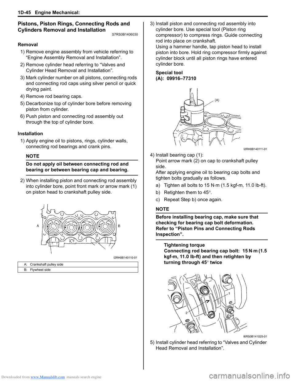
2) When installing piston and connecting rod assembly into cylinder bore, point front mark or arrow mark (1)
on piston head to crankshaft pulley side. 3) Install piston and connecting rod assembly into
cylinder bore. Use special tool (Piston ring
compressor) to compress rings. Guide connecting
rod into place on crankshaft.
Using a hammer handle, tap piston head to install
piston into bore. Hold ring compressor firmly against
cylinder block until all piston rings have entered
cylinder bore.
Special tool
(A): 09916–77310
4) Install bearing cap (1): Point arrow mark (2) on cap to crankshaft pulley
side.
After applying engine oil to bearing cap bolts and
tighten bolts gradually as follows.
a) Tighten all bolts to 15 N ⋅m (1.5 kgf-m, 11.0 lb-ft).
b) Retighten them to 45 °.
c) Repeat Step b) once again.
NOTE
Before installing bearing cap, make sure that
checking for bearing cap bolt deformation.
Refer to “Piston Pins and Connecting Rods
Inspection”.
Tightening torque
Connecting rod bearing cap bolt: 15 N ⋅m (1.5
kgf-m, 11.0 lb-ft) and then retighten by
turning through 45 ° twice
5) Install cylinder head referring to “Valves and Cylinder Head Removal and Installation”.
A: Crankshaft pulley side
B: Flywheel side
I2RH0B140110-01
I2RH0B140111-01
I6RS0B141025-01
Page 331 of 1496
Downloaded from www.Manualslib.com manuals search engine Engine Mechanical: 1D-46
Pistons, Piston Rings, Connecting Rods and
Cylinders Disassembly and Assembly
S7RS0B1406031
Disassembly1) Using piston ring expander, remove two compression rings (Top and 2nd) and oil ring from
piston.
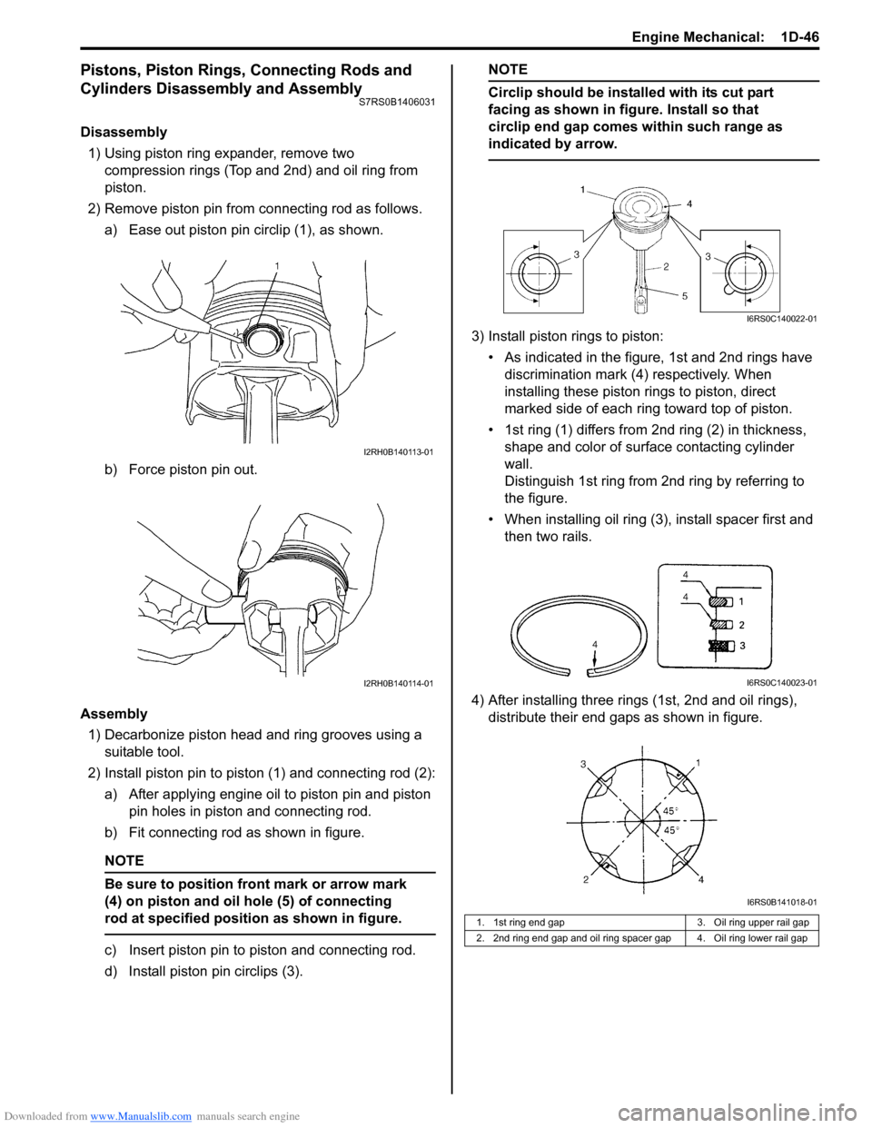
2) Remove piston pin from connecting rod as follows. a) Ease out piston pin circlip (1), as shown.
b) Force piston pin out.
Assembly 1) Decarbonize piston head and ring grooves using a suitable tool.
2) Install piston pin to piston (1) and connecting rod (2): a) After applying engine oil to piston pin and piston pin holes in piston and connecting rod.
b) Fit connecting rod as shown in figure.
NOTE
Be sure to position front mark or arrow mark
(4) on piston and oil hole (5) of connecting
rod at specified position as shown in figure.
c) Insert piston pin to piston and connecting rod.
d) Install piston pin circlips (3).
NOTE
Circlip should be installed with its cut part
facing as shown in figure. Install so that
circlip end gap comes within such range as
indicated by arrow.
3) Install piston rings to piston:
• As indicated in the figure, 1st and 2nd rings have discrimination mark (4) respectively. When
installing these piston rings to piston, direct
marked side of each ring toward top of piston.
• 1st ring (1) differs from 2nd ring (2) in thickness, shape and color of surface contacting cylinder
wall.
Distinguish 1st ring from 2nd ring by referring to
the figure.
• When installing oil ring (3), install spacer first and then two rails.
4) After installing three rings (1st, 2nd and oil rings), distribute their end gaps as shown in figure.
I2RH0B140113-01
I2RH0B140114-01
1. 1st ring end gap 3. Oil ring upper rail gap
2. 2nd ring end gap and oil ring spacer gap 4. Oil ring lower rail gap
I6RS0C140022-01
I6RS0C140023-01
I6RS0B141018-01