Wiring circuit SUZUKI SWIFT 2007 2.G Service Workshop Manual
[x] Cancel search | Manufacturer: SUZUKI, Model Year: 2007, Model line: SWIFT, Model: SUZUKI SWIFT 2007 2.GPages: 1496, PDF Size: 34.44 MB
Page 1262 of 1496
Downloaded from www.Manualslib.com manuals search engine 9A-91 Wiring Systems:
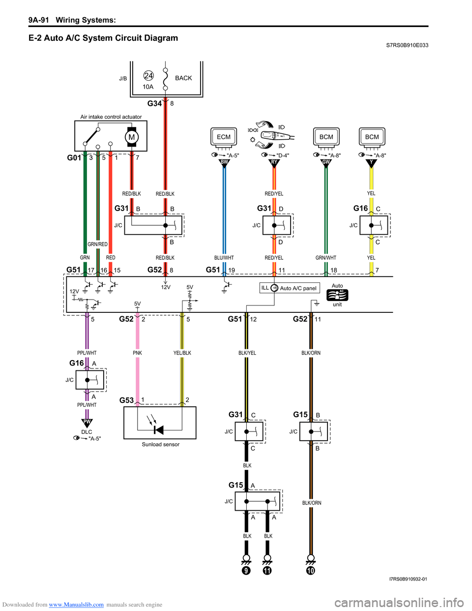
E-2 Auto A/C System Circuit DiagramS7RS0B910E033
12G53
G51
G52
G51
G52 G52 G51
251211
11
15
17
12V
198
REDGRN
RED/BLK
GRN/RED
RED/YEL
RED/YELRED/BLK
RED/BLKBLU/WHT
M
7133G01
8G34
ILL
Auto A/C panel
Sunload sensor
DLC Auto
unit
Air intake control actuator
BACK
10A24
"A-5"
PW
"A-5"BW"D-4"RY
18
GRN/WHT
"A-8"GW
ECMBCMBCM
BLK/ORN
YEL/BLKPNK
5
PPL/WHT
PPL/WHT
BLK/ORNBLK/YEL
5V 5V
12V
J/B
7
YEL
YEL
"A-8"Y
109
G31
J/C
D
D
G15
J/C
B
B
BLK
BLK
G31
J/C
C
C
G16
J/C
C
C
G15
J/C
A A
11
BLK
A
G16
J/C
A
A
J/C
BG31B B
16
5
I7RS0B910932-01
Page 1263 of 1496
Downloaded from www.Manualslib.com manuals search engine Wiring Systems: 9A-92
G091
2
346
1698G52 G51
G52 G52
G51 G51G52
1
3
7
G495
6
M
G48
M
2
31141413
341
M
2G46
5G33
WHT/RED
WHT/RED
BLK/WHT
GRY/REDGRY/BLUWHTWHT/BLUBRN/WHTBRN/YELWHT/BLKGRN
WHTYELWHTWHT/BLU
GRNGRNBLKGRNGRN
BLK/YELBLK/YEL
BLK/WHTGRYBLK/WHTBLU/RED
Blower motor controller
A/C
DiodeAutounit
Blower
motor
15A RADIO
Evaporator
temperature
sensor Air flow control
actuator
Temperature
control actuator
40
635
71 2
G47
G051
2 1
5V5V
5V5V 12V
12V
12V
J/B
J/B
G326
1 2
5
3
30A HTR
FAN
4
10A
38IG2
SIG
Blowermotorrelay
E39
7
G349
G15
J/C
912
A
A
BLK
11
A
BLKBLK
BLU
J/C
B BG16
B
G16
J/C
DDDD
G17
J/C
B
B
Individual circuit fuse box (No.1)
G502
1
PNK/BLK
Inside air
temperature
sensor
5V
I7RS0B910946-02
Page 1264 of 1496
Downloaded from www.Manualslib.com manuals search engine 9A-93 Wiring Systems:
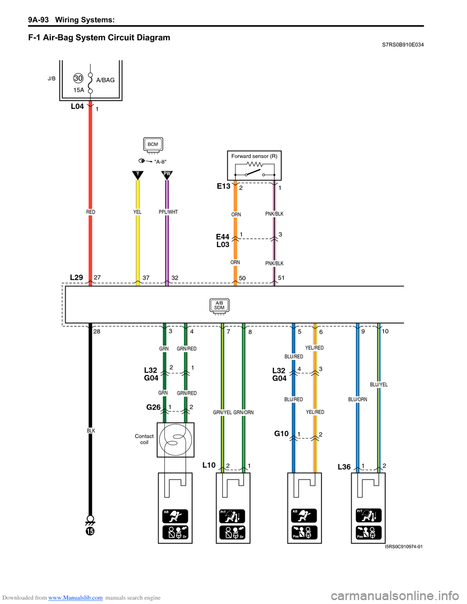
F-1 Air-Bag System Circuit DiagramS7RS0B910E034
3
ORN
YPW
A/B
SDM
L29
J/B
15A A/BAG
30
RED
L04
BCM
15
BLK
1
E44
L031
PNK/BLK
E13
Forward sensor (R)
1
2
Contact
coil
G2612
L32
G0421
L1021
YEL/RED
GRN/RED
G101 2
43
YEL/RED
L3612
3
4 7
856910
28 27
37 32 5051
"A-8"
L32
G04
ORN
PNK/BLKYELPPL/WHT
GRN
GRNGRN/RED
GRN/YELGRN/ORN
BLU/RED
BLU/REDBLU/ORN
BLU/YEL
I5RS0C910974-01
Page 1266 of 1496
Downloaded from www.Manualslib.com manuals search engine 9A-95 Wiring Systems:
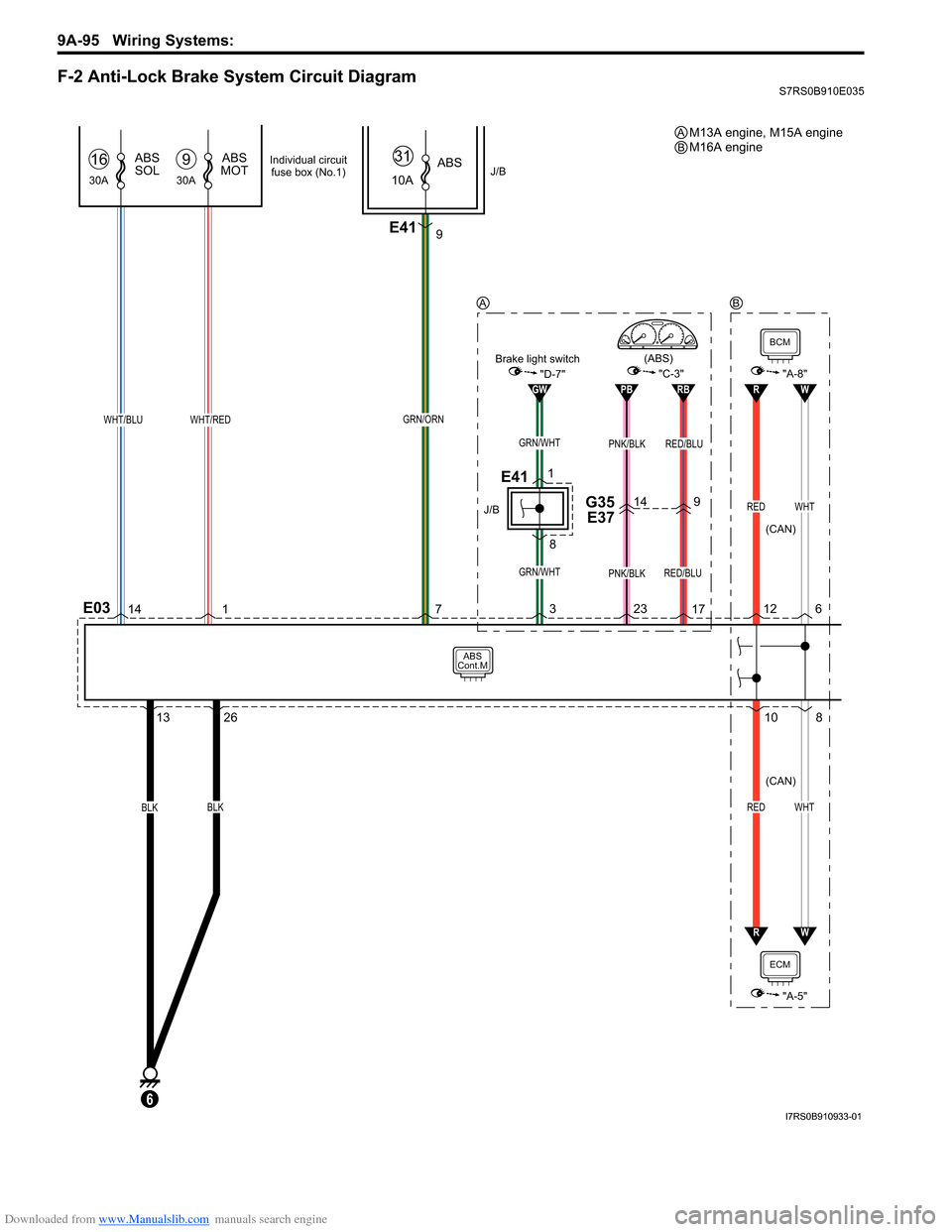
F-2 Anti-Lock Brake System Circuit DiagramS7RS0B910E035
1326
14
1 3
23
17
E03
ABS
Cont.M
BCM
BLK
30A
ABS
SOL16
30A
ABS
MOT9
WHT/REDWHT/BLU
GRN/WHT
6
BLKREDWHT
PNK/BLK
PB
PNK/BLK
RB
RED/BLU
RED/BLU
149G35 E37
"C-3""A-8"
ECM
"A-5"
J/B10A ABS
31
E419
GRN/ORN
7
GW"D-7"Brake light switch
(CAN)
(CAN)
(ABS)
GRN/WHT
J/B
E411
8
Individual circuit fuse box (No.1)
108
12
RED
R
6
WHT
W
RW
M13A engine, M15A engine
M16A engineA
AB
B
I7RS0B910933-01
Page 1268 of 1496
Downloaded from www.Manualslib.com manuals search engine 9A-97 Wiring Systems:
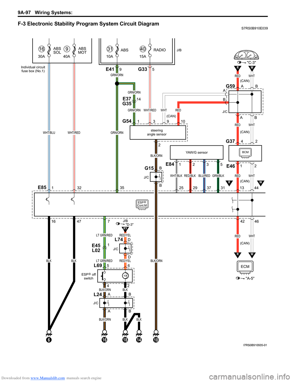
F-3 Electronic Stability Program System Circuit DiagramS7RS0B910E039
1647
132 13
44E85
BLK
ABS
SOLABS
MOT
WHT/REDWHT/BLU
6
BLK
REDWHT
REDWHT
REDWHT
25
BLK/ORN
GRN/ORN
GRN/ORN
GRN/ORN
Individual circuit
fuse box (No.1) J/B
ABS
GRN/ORN
ECM
35
"A-5"
"C-3"
steering
angle sensor
RED
R
4246
WHT
W
RW
1
4G37
E46
2
2
BCM
A
A
A
BG59
B
B
RW
2
1
WHT/REDWHTRED
3910
(CAN) (CAN)
(CAN)
(CAN)
(CAN)
7
ESP
Cont.M
1E45 L02
LT GRN/RED
LT GRN/REDRED/YEL
RED/YEL
BLK/ORN
WHT/BLK
RY
J/C J/C
B
BLKBLK
BLK/ORN
BLK/ORN
16181410
BLK
ESP off
switch
L6956
42
G15
G541
29
RED/BLK
2
37
BLU/RED
3
31
GRN/BLK
5E84B
J/C
D
L74D
R
R
"D-3"J/B
YAW/G sensor
J/C
A
L24A
B
B
30A
16
40A
9
10A
31
15A
RADIO
40
E419G335
E37
G3514
I7RS0B910935-01
Page 1270 of 1496
Downloaded from www.Manualslib.com manuals search engine 9A-99 Wiring Systems:
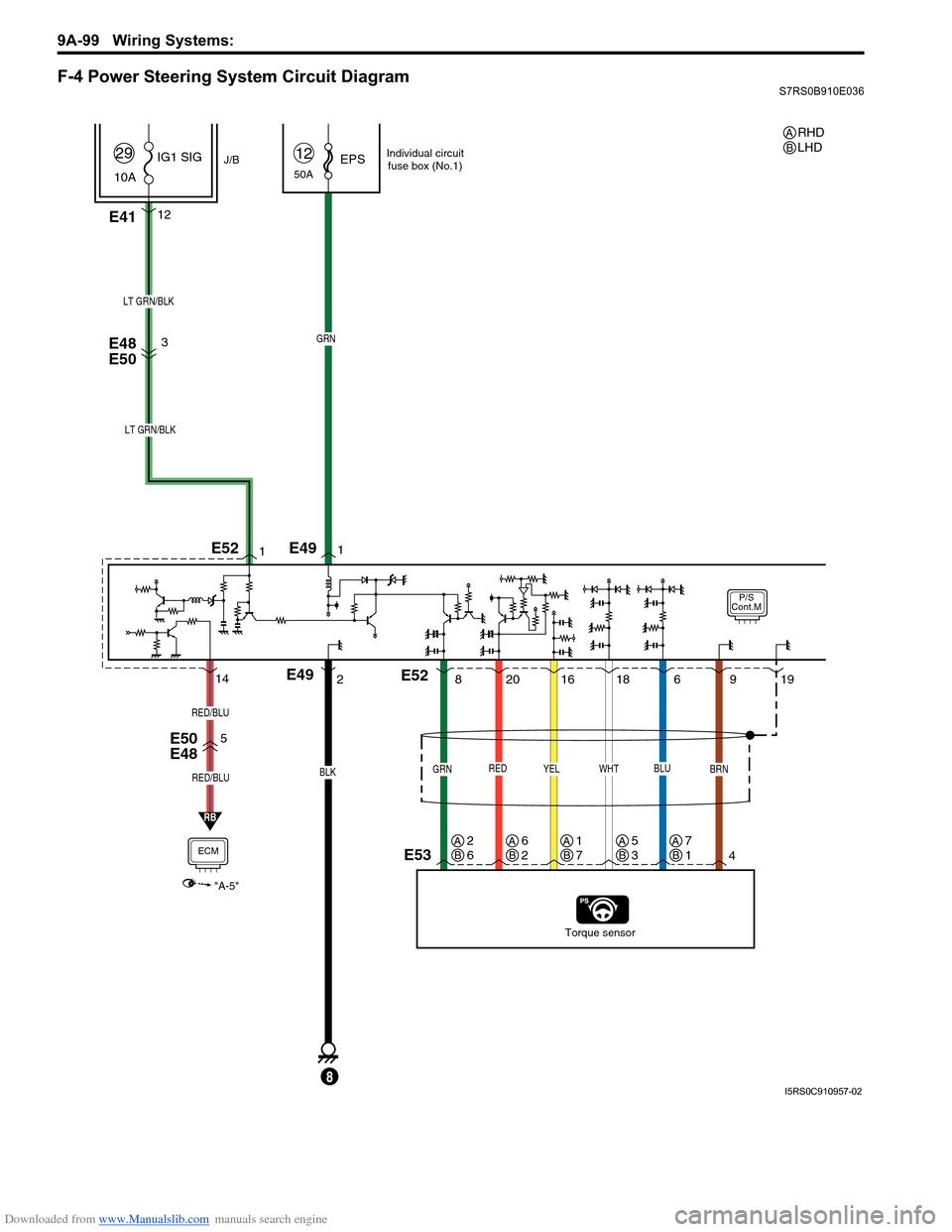
F-4 Power Steering System Circuit DiagramS7RS0B910E036
P/S
Cont.M
50AEPS12
E4112
J/B
10A IG1 SIG
29
RED
20
E48
E50
E50
E48
Torque sensor
BLK
E49
8
GRN
LT GRN/BLK
YEL
16
GRN
8
BRN
49
WHT
18
BLU
619
1
21
LT GRN/BLK
3
E53
E49
E52
E52
RB
5
ECM
"A-5"
RED/BLU
RED/BLU
14
Individual circuit
fuse box (No.1)
RHD
LHDAB
AB2
6AB6
2AB1
7AB5
3AB7
1
I5RS0C910957-02
Page 1272 of 1496
Downloaded from www.Manualslib.com manuals search engine 9A-101 Wiring Systems:
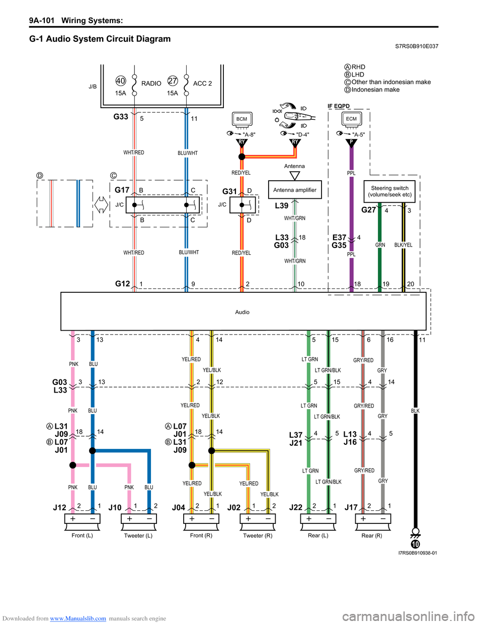
G-1 Audio System Circuit DiagramS7RS0B910E037
PPL
PPL
G335
GRY
18141814L37J21
G03 L333 13 2
515 14
4 5
4
5
11
21 1
2 2
1 1
2 2
1 2
1
3
13 4
14 5
15 6
16 11
RY"D-4"RY
WHT/RED
G121
J/C
G17
WHT/RED
J/B15ARADIO
40
RED/YEL
J/C
G31
BCM
"A-8"
Antenna amplifier
WHT/GRN
L39
L33
G0318E37
G354
WHT/GRN
BLU/WHT
BLU/WHT
15A ACC 2
27
BLK
10
Tweeter (L)Front (L)
PNKBLU
J12
J10
Tweeter (R)Front (R)
J04J02
YEL/BLK
YEL/RED
Rear (R)Rear (L)
LT GRN
LT GRN/BLKPNKBLUPNKBLUYEL/BLK
YEL/RED
YEL/BLK
YEL/REDLT GRN
LT GRN/BLK
GRY/RED
GRY
GRY/RED
PNKBLUYEL/BLK
YEL/REDLT GRN
LT GRN/BLKGRY
GRY/RED
12
Audio
RED/YEL
921 0
J22J17
B
B C
C D
DSteering switch
(volume/seek etc)
G27
GRN
1920
BLK/YEL
4 3
L13
J16
4
P
ECM
"A-5"
18
RHD
LHD
Other than indonesian make
Indonesian make
ABC
DC
D
Antenna
L31
J09
L07 J01A
B
L07 J01
L31 J09A
B
IF EQPD
I7RS0B910938-01
Page 1273 of 1496
Downloaded from www.Manualslib.com manuals search engine Wiring Systems: 9A-102
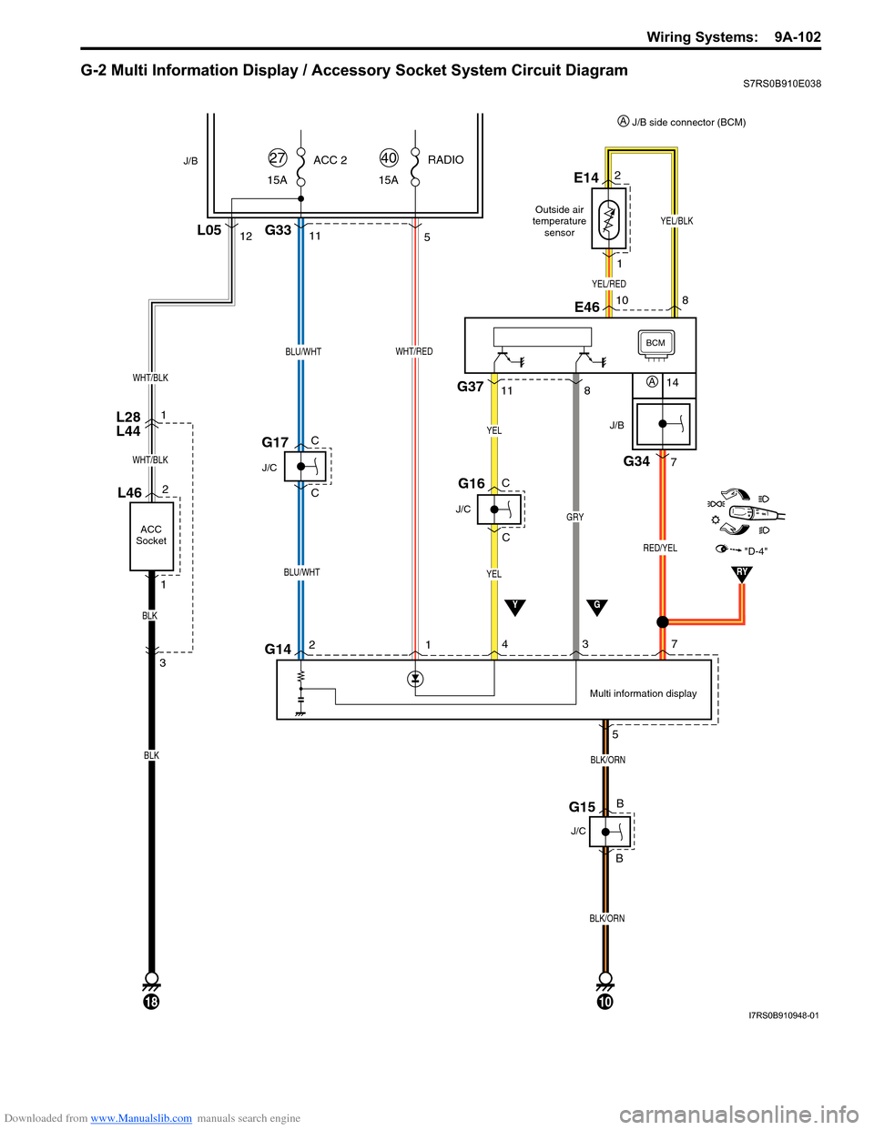
G-2 Multi Information Display / Accessory Socket System Circuit DiagramS7RS0B910E038
11
BLU/WHT
BLU/WHT
15AACC 2
27
J/C
G17
L28
L44
YG
Multi information display
J/B
BCM
J/B
G34
7
14
RED/YEL
10
BLK/ORN
2
BLK/ORN
15A RADIO
40
G335
WHT/RED
G141
3
J/C
YEL
YEL
G16
4
57
G15
J/C
12L05
WHT/BLK
L46
ACC
Socket
2
1
18
WHT/BLK
BLK
BLK
3 1
C
C
B
B
C
C
GRY
G378
11
"D-4"
RY
YEL/RED
YEL/BLK
2E14
1
8
10E46
A
J/B side connector (BCM)
A
Outside air
temperature sensor
I7RS0B910948-01
Page 1284 of 1496
Downloaded from www.Manualslib.com manuals search engine 9B-2 Lighting Systems:
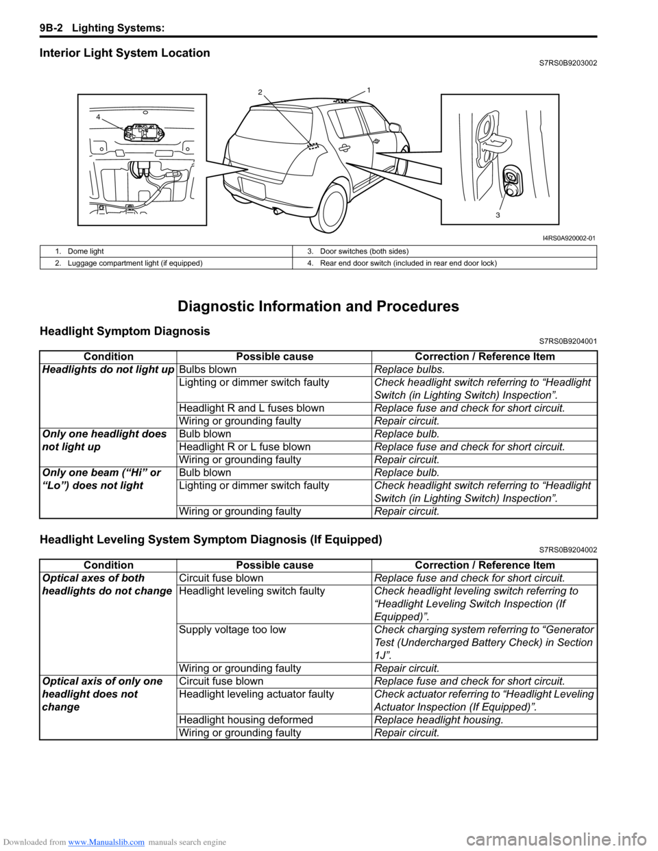
Interior Light System LocationS7RS0B9203002
Diagnostic Information and Procedures
Headlight Symptom DiagnosisS7RS0B9204001
Headlight Leveling System Symptom Diagnosis (If Equipped)S7RS0B9204002
13
2
4
I4RS0A920002-01
1. Dome light 3. Door switches (both sides)
2. Luggage compartment light (if equipped) 4. Rear end door switch (included in rear end door lock)
ConditionPossible cause Correction / Reference Item
Headlights do not light up Bulbs blown Replace bulbs.
Lighting or dimmer switch faulty Check headlight switch referring to “Headlight
Switch (in Lighting Switch) Inspection”.
Headlight R and L fuses blown Replace fuse and check for short circuit.
Wiring or grounding faulty Repair circuit.
Only one headlight does
not light up Bulb blown
Replace bulb.
Headlight R or L fuse blown Replace fuse and check for short circuit.
Wiring or grounding faulty Repair circuit.
Only one beam (“Hi” or
“Lo”) does not light Bulb blown
Replace bulb.
Lighting or dimmer switch faulty Check headlight switch referring to “Headlight
Switch (in Lighting Switch) Inspection”.
Wiring or grounding faulty Repair circuit.
ConditionPossible cause Correction / Reference Item
Optical axes of both
headlights do not change Circuit fuse blown
Replace fuse and check for short circuit.
Headlight leveling switch faulty Check headlight leveling switch referring to
“Headlight Leveling Switch Inspection (If
Equipped)”.
Supply voltage too low Check charging system referring to “Generator
Test (Undercharged Battery Check) in Section
1J”.
Wiring or grounding faulty Repair circuit.
Optical axis of only one
headlight does not
change Circuit fuse blown
Replace fuse and check for short circuit.
Headlight leveling actuator faulty Check actuator referring to “Headlight Leveling
Actuator Inspection (If Equipped)”.
Headlight housing deformed Replace headlight housing.
Wiring or grounding faulty Repair circuit.
Page 1285 of 1496
Downloaded from www.Manualslib.com manuals search engine Lighting Systems: 9B-3
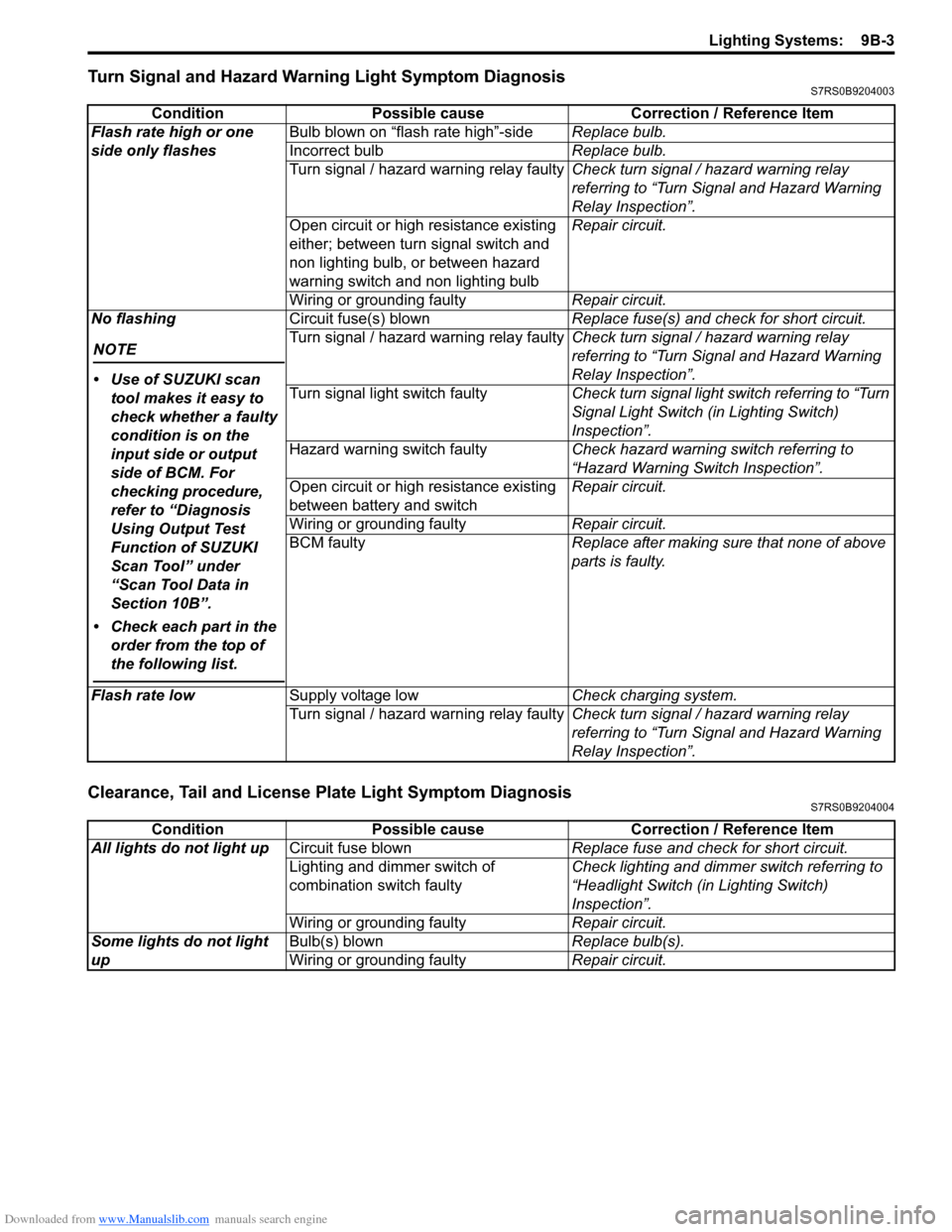
Turn Signal and Hazard Warning Light Symptom DiagnosisS7RS0B9204003
Clearance, Tail and License Plate Light Symptom DiagnosisS7RS0B9204004
ConditionPossible cause Correction / Reference Item
Flash rate high or one
side only flashes Bulb blown on “flash rate high”-side
Replace bulb.
Incorrect bulb Replace bulb.
Turn signal / hazard warning relay faulty Check turn signal / hazard warning relay
referring to “Turn Signal and Hazard Warning
Relay Inspection”.
Open circuit or high resistance existing
either; between turn signal switch and
non lighting bulb, or between hazard
warning switch and non lighting bulb Repair circuit.
Wiring or grounding faulty Repair circuit.
No flashing
NOTE
• Use of SUZUKI scan tool makes it easy to
check whether a faulty
condition is on the
input side or output
side of BCM. For
checking procedure,
refer to “Diagnosis
Using Output Test
Function of SUZUKI
Scan Tool” under
“Scan Tool Data in
Section 10B”.
• Check each part in the order from the top of
the following list.
Circuit fuse(s) blown Replace fuse(s) and check for short circuit.
Turn signal / hazard warning relay faulty Check turn signal / hazard warning relay
referring to “Turn Signal and Hazard Warning
Relay Inspection”.
Turn signal light switch faulty Check turn signal light switch referring to “Turn
Signal Light Switch (in Lighting Switch)
Inspection”.
Hazard warning switch faulty Check hazard warning switch referring to
“Hazard Warning Switch Inspection”.
Open circuit or high resistance existing
between battery and switch Repair circuit.
Wiring or grounding faulty Repair circuit.
BCM faulty Replace after making sure that none of above
parts is faulty.
Flash rate low Supply voltage low Check charging system.
Turn signal / hazard warning relay faulty Check turn signal / hazard warning relay
referring to “Turn Signal and Hazard Warning
Relay Inspection”.
ConditionPossible cause Correction / Reference Item
All lights do not light up Circuit fuse blown Replace fuse and check for short circuit.
Lighting and dimmer switch of
combination switch faulty Check lighting and dimmer switch referring to
“Headlight Switch (in Lighting Switch)
Inspection”.
Wiring or grounding faulty Repair circuit.
Some lights do not light
up Bulb(s) blown
Replace bulb(s).
Wiring or grounding faulty Repair circuit.