body harness SUZUKI SWIFT 2007 2.G Service Owner's Manual
[x] Cancel search | Manufacturer: SUZUKI, Model Year: 2007, Model line: SWIFT, Model: SUZUKI SWIFT 2007 2.GPages: 1496, PDF Size: 34.44 MB
Page 217 of 1496

Downloaded from www.Manualslib.com manuals search engine Engine General Information and Diagnosis: 1A-167
4ECM voltage check
1) Disconnect connector from APP sensor with ignition
switch turned OFF.
2) Check for proper connection to APP sensor at “RED”, “YEL” and “WHT” wire terminals.
3) If OK, measure voltage between “RED” wire terminal of APP sensor connector and vehicle body ground with
ignition switch turned ON.
Is voltage 4 – 6 V? Go to Step 6. Go to Step 5.
5 Wire harness check
1) Disconnect connectors from ECM with ignition switch
turned OFF.
2) Check for proper connection of ECM connector at “E23- 34” terminal.
3) If OK, measure voltage between “E23-34” terminal of ECM connector and engine ground with ignition switch
turned ON.
Is voltage 0 V? Substitute a known-
good ECM and recheck.
“RED” wire is shorted to
power circuit.
6 Wire harness check
1) Disconnect connectors from ECM with ignition switch
turned OFF.
2) Check for proper connection of ECM connector at “E23- 35”, “E23-36” and “E23-34” terminals.
3) If OK, measure resistance between “YEL” wire terminal and each “BRN”, “RED” wire terminals of APP sensor
connector.
Is each resistance infinity? Go to Step 7. “YEL” wire is shorted to
“BRN” wire and/or
“RED” wire.
7 Wire harness check
1) Turn ON ignition switch.
2) Measure voltage between “E23-36” terminal of ECM
connector and engine ground.
Is voltage 0 V? Go to Step 8. “YEL” wire is shorted to
power circuit.
8 Ground circuit check
1) Connect connectors to ECM with ignition switch turned
OFF.
2) Measure resistance between “WHT” wire terminal of APP sensor connector and vehicle body ground.
Is resistance below 5
Ω? Go to Step 10. Go to Step 9.
Step Action Yes No
"GRN"
"BLU"
"BRN"
"YEL"
"WHT"
"RED"
I4RS0B110048-01
Page 220 of 1496

Downloaded from www.Manualslib.com manuals search engine 1A-170 Engine General Information and Diagnosis:
4Wire harness check
1) Disconnect connectors from ECM with ignition switch
turned OFF.
2) Measure resistance between “C37-43” terminal of ECM connector and engine ground.
Is resistance infinity? Go to Step 5. “RED” wire is shorted to
other circuit.
5 Wire harness check
1) Measure voltage between “C37-43” terminal of ECM
connector and engine ground with ignition switch turned
ON.
Is voltage 0 V? Substitute a known-
good ECM and recheck.
“RED” wire is shorted to
other circuit.
6 Wire harness check
1) Measure voltage between “GRN” wire terminal of electric
throttle body connector and engine ground, between
“WHT” wire terminal of electric throttle body connector
and engine ground with ignition switch turned ON.
Is each voltage 4 – 6 V? Go to Step 9. Go to Step 7.
7 Wire harness check
1) Turn OFF ignition switch.
2) Disconnect connectors from ECM.
3) Check for proper connection of ECM connector at “C37-
54” and “C37-40” terminals.
4) If OK, measure voltage between “C37-54” terminal of ECM connector and engine ground, between “C37-40”
terminal of ECM connector and engine ground.
Is each voltage 0 V? Go to Step 8. “GRN” wire or “WHT”
wire is shorted to other
circuit.
8 Wire harness check
1) Measure resistance between “GRN” wire terminal of
electric throttle body connector and engine ground,
between “WHT” wire terminal of electric throttle body
connector and engine ground with ignition switch turned
OFF.
Is each resistance infinity? Substitute a known-
good ECM and recheck.
“GRN” wire or “WHT”
wire is shorted to other
circuit.
9 Electric throttle body check
1) Check TP sensor referring to “Throttle Position Sensor
Performance Check” under “Electric Throttle Body
Assembly On-Vehicle Inspection in Section 1C”.
Is each output voltage within specified value? Substitute a known-
good ECM and recheck.
Replace electric throttle
body.
Step Action Yes No
Page 222 of 1496
Downloaded from www.Manualslib.com manuals search engine 1A-172 Engine General Information and Diagnosis:
DTC Troubleshooting
NOTE
• When measuring circuit voltage, resistance and/or pulse signal at ECM connector, connect the
special tool to ECM and/or the ECM connectors re ferring to “Inspection of ECM and Its Circuits”.
• Upon completion of inspection and repair work, perform “DTC Confirmation Procedure” and confirm that the trouble has been corrected.
Step Action YesNo
1 Was “Engine and Emission Control System Check”
performed? Go to Step 2.
Go to “Engine and
Emission Control
System Check”.
2 APP sensor and its circuit check
1) Connect scan tool to DLC with ignition switch turned
OFF.
2) Turn ON ignition switch.
3) Check each voltage of “APP Sensor 1 Volt” and “APP Sensor 2 Volt” displayed on scan tool when accelerator
pedal is idle position and fully depressed.
Is displayed each APP sensor value as described voltage in
“Scan Tool Data”? Intermittent trouble.
Check for intermittent
referring to “Intermittent
and Poor Connection
Inspection in Section
00”.
Go to Step 3.
3 ECM voltage check
1) Disconnect connector from APP sensor with ignition
switch turned OFF.
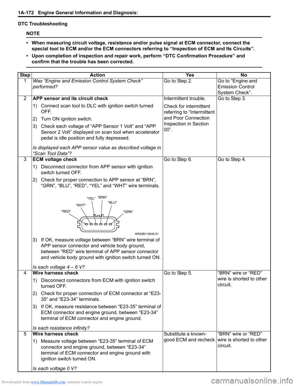
2) Check for proper connection to APP sensor at “BRN”, “GRN”, “BLU”, “RED”, “YEL” and “WHT” wire terminals.
3) If OK, measure voltage between “BRN” wire terminal of APP sensor connector and vehicle body ground,
between “RED” wire terminal of APP sensor connector
and vehicle body ground with ignition switch turned ON.
Is each voltage 4 – 6 V? Go to Step 6.
Go to Step 4.
4 Wire harness check
1) Disconnect connectors from ECM with ignition switch
turned OFF.
2) Check for proper connection of ECM connector at “E23- 35” and “E23-34” terminals.
3) If OK, measure resistance between “E23-35” terminal of ECM connector and engine ground, between “E23-34”
terminal of ECM connector and engine ground.
Is each resistance infinity? Go to Step 5.
“BRN” wire or “RED”
wire is shorted to other
circuit.
5 Wire harness check
1) Measure voltage between “E23-35” terminal of ECM
connector and engine ground, between “E23-34”
terminal of ECM connector and engine ground with
ignition switch turned ON.
Is each voltage 0 V? Substitute a known-
good ECM and recheck.
“BRN” wire or “RED”
wire is shorted to other
circuit.
"GRN"
"BLU"
"BRN"
"YEL"
"WHT"
"RED"
I4RS0B110048-01
Page 223 of 1496
Downloaded from www.Manualslib.com manuals search engine Engine General Information and Diagnosis: 1A-173
DTC P2227 / P2228 / P2229: Barometric Pressure Circuit MalfunctionS7RS0B1104078
DTC P2227: Barometric Pressure Circuit Range / Performance
DTC P2228: Barometric Pressure Circuit Low
DTC P2229: Barometric Pressure Circuit High
System Description
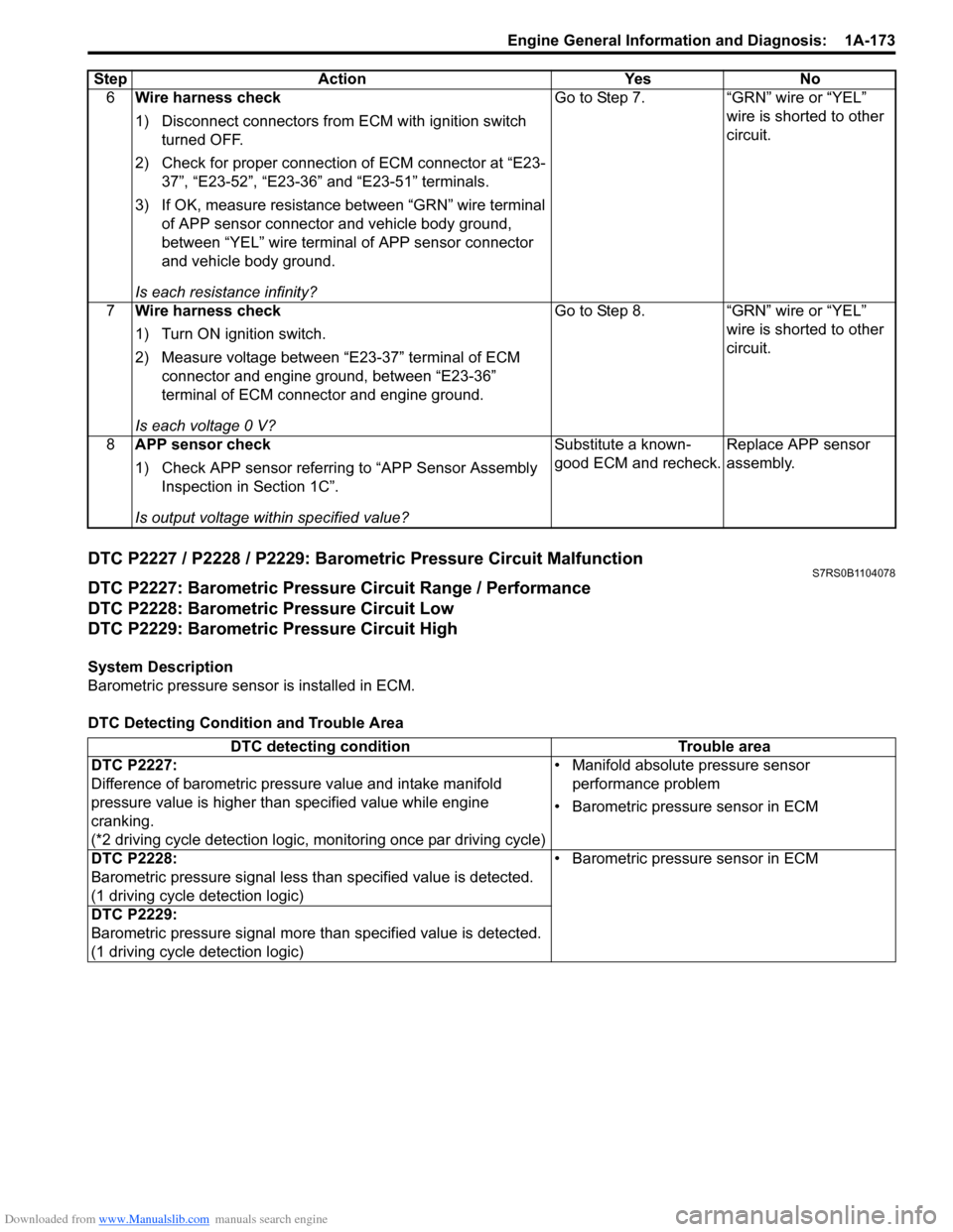
Barometric pressure sensor is installed in ECM.
DTC Detecting Condition and Trouble Area6
Wire harness check
1) Disconnect connectors from ECM with ignition switch
turned OFF.
2) Check for proper connection of ECM connector at “E23- 37”, “E23-52”, “E23-36” and “E23-51” terminals.
3) If OK, measure resistance between “GRN” wire terminal of APP sensor connector and vehicle body ground,
between “YEL” wire terminal of APP sensor connector
and vehicle body ground.
Is each resistance infinity? Go to Step 7. “GRN” wire or “YEL”
wire is shorted to other
circuit.
7 Wire harness check
1) Turn ON ignition switch.
2) Measure voltage between “E23-37” terminal of ECM
connector and engine ground, between “E23-36”
terminal of ECM connector and engine ground.
Is each voltage 0 V? Go to Step 8. “GRN” wire or “YEL”
wire is shorted to other
circuit.
8 APP sensor check
1) Check APP sensor referring to “APP Sensor Assembly
Inspection in Section 1C”.
Is output voltage within specified value? Substitute a known-
good ECM and recheck.
Replace APP sensor
assembly.
Step Action Yes No
DTC detecting condition
Trouble area
DTC P2227:
Difference of barometric pressure value and intake manifold
pressure value is higher than specified value while engine
cranking.
(*2 driving cycle detection logic, monitoring once par driving cycle) • Manifold absolute pressure sensor
performance problem
• Barometric pressure sensor in ECM
DTC P2228:
Barometric pressure signal less than specified value is detected.
(1 driving cycle detection logic) • Barometric pressure sensor in ECM
DTC P2229:
Barometric pressure signal more than specified value is detected.
(1 driving cycle detection logic)
Page 302 of 1496

Downloaded from www.Manualslib.com manuals search engine 1D-17 Engine Mechanical:
Engine Assembly Removal and InstallationS7RS0B1406011
NOTE
After replacing electric throttle body
assembly, perform calibration of throttle
valve referring to “Electric Throttle Body
System Calibration in Section 1C”.
Removal1) Relieve fuel pressure according to “Fuel Pressure Relief Procedure in Section 1G”.
2) Disconnect negative and pos itive cable at battery.
3) Remove battery and tray.
4) Remove engine hood after disconnecting windshield washer hose.
5) Remove right and left side engine under covers.
6) Remove A/C compressor belt by referring to “Compressor Drive Belt Remo val and Installation in
Section 7B” or “Compressor Drive Belt Removal and
Installation in Section 7B”.
7) Drain engine oil, transaxle oil and coolant.
8) Remove cowl top plate referring to “Cowl Top Components in Section 9K”.
9) Remove air cleaner assembly referring to “Air Cleaner Components”.
10) With hose connected, detach A/C compressor from its bracket (A/C model) referring to “Compressor
Assembly Removal and Installation in Section 7B” or
“Compressor Assembly Removal and Installation in
Section 7B”.
CAUTION!
Suspend removed A/C compressor at a place
where no damage will be caused during
removal and installation of engine assembly.
11) Remove intake manifold rear stiffener (1) from intake manifold and cylinder block. 12) Disconnect the following electric wires:
• MAP sensor (1)
• ECT sensor (2)
•EGR valve (3)
• CMP sensor (4)
• Electric throttle body assembly (5)
• Ignition coil assembly (6)
• Injectors (7)
• Heated oxygen sensor No. 2 (8) and No. 1 (9)
• Oil control valve (10)
• Engine oil pressure switch (11)
• CKP sensor (12)
• Knock sensor (13)
• Back up light switch (14)
• Generator (15)
• Starting motor (16)
• Ground terminal (17) from intake manifold
• Battery ground terminal (18) from exhaust manifold
• Battery ground cable (19) from transaxle
• Magnet clutch switch of A/C compressor (A/C model)
• Each wire harness clamps
• Output shaft speed sensor (VSS) (34) (A/T model)
• Solenoid valve (33) (A/T model)
• Transmission range sensor (32) (A/T model)
• Input shaft speed sensor (31) (A/T model)
13) Remove fuse box from its bracket.
14) Disconnect the following cables: • Gear select control cable (23) (M/T model)
• Gear shift control cable (24) (M/T model)
• A/T select cable (A/T model)
15) Disconnect the following hoses: • Brake booster hose (26) from intake manifold
• Radiator inlet and outlet hoses (20) from each pipe
• Heater inlet and outlet hoses (21) from each pipe
• Fuel feed hoses (22) from fuel feed pipe
• EVAP canister purge valve hose (30) from purge pipe
• A/T fluid cooler hoses (A/T model)
16) With hose connected, detach clutch operating cylinder (25). (M/T model)
CAUTION!
Suspend removed clutch operating cylinder
at a place where no damage will be caused
during removal and installation of engine
assembly.
1
I6RS0B141014-01
Page 597 of 1496
Downloaded from www.Manualslib.com manuals search engine Electronic Stability Program: 4F-23
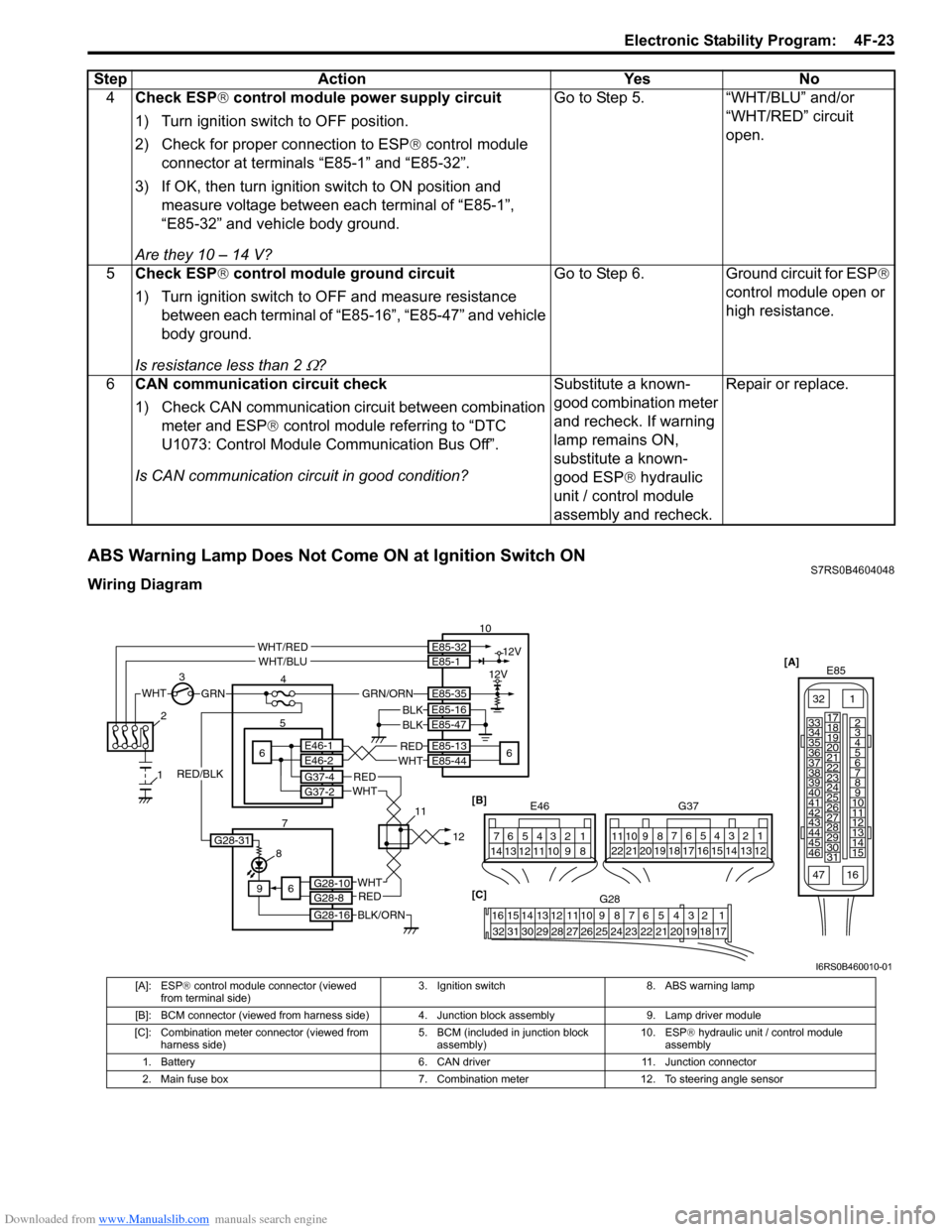
ABS Warning Lamp Does Not Come ON at Ignition Switch ONS7RS0B4604048
Wiring Diagram4
Check ESP ® control module power supply circuit
1) Turn ignition switch to OFF position.
2) Check for proper connection to ESP ® control module
connector at terminals “E85-1” and “E85-32”.
3) If OK, then turn ignition switch to ON position and measure voltage between each terminal of “E85-1”,
“E85-32” and vehicle body ground.
Are they 10 – 14 V? Go to Step 5. “WHT/BLU” and/or
“WHT/RED” circuit
open.
5 Check ESP ® control module ground circuit
1) Turn ignition switch to OFF and measure resistance between each terminal of “E85-16”, “E85-47” and vehicle
body ground.
Is resistance less than 2
Ω? Go to Step 6.
Ground circuit for ESP®
control module open or
high resistance.
6 CAN communication circuit check
1) Check CAN communication circuit between combination
meter and ESP ® control module referring to “DTC
U1073: Control Module Communication Bus Off”.
Is CAN communication circuit in good condition? Substitute a known-
good combination meter
and recheck. If warning
lamp remains ON,
substitute a known-
good ESP
® hydraulic
unit / control module
assembly and recheck. Repair or replace.
Step
Action YesNo
[A]
E85
161
15
2
3
4
5
6
7
8
9
10
11
12
13
14
17
18
19
20
21
22
23
24
25
26
27
28
29
30
31
3233
34
35
36
37
38
39
40
41
42
43
44
45
46
47
WHTGRN
3
E85-13
E85-44REDWHT6 5E46-1E46-2
4 10
6
E85-16
E85-47BLKBLK
8
9
BLK/ORN
REDWHT
REDWHT
G37-4G37-2
G28-10G28-8
G28-16
12V
12VE85-32E85-1
E85-35
WHT/REDWHT/BLU
GRN/ORN
6
2
1
7 1112[B]
G37
E46124
53
67
891011121314124
53
67
891011
1213141516171819202122
[C] G28
12345678910111213141516
17181920212223242526272829303132
G28-31
RED/BLK
I6RS0B460010-01
[A]: ESP ® control module connector (viewed
from terminal side) 3. Ignition switch 8. ABS warning lamp
[B]: BCM connector (viewed from harness side) 4. Junction block assembly 9. Lamp driver module
[C]: Combination meter connector (viewed from harness side) 5. BCM (included in junction block
assembly) 10. ESP
® hydraulic unit / control module
assembly
1. Battery 6. CAN driver11. Junction connector
2. Main fuse box 7. Combination meter12. To steering angle sensor
Page 600 of 1496
![SUZUKI SWIFT 2007 2.G Service Owners Manual Downloaded from www.Manualslib.com manuals search engine 4F-26 Electronic Stability Program:
Serial Data Link Circuit CheckS7RS0B4604012
Wiring Diagram
Inspection
[A]E85
161
15
2
3
4
5
6
7
8
9
10
11
SUZUKI SWIFT 2007 2.G Service Owners Manual Downloaded from www.Manualslib.com manuals search engine 4F-26 Electronic Stability Program:
Serial Data Link Circuit CheckS7RS0B4604012
Wiring Diagram
Inspection
[A]E85
161
15
2
3
4
5
6
7
8
9
10
11](/img/20/7607/w960_7607-599.png)
Downloaded from www.Manualslib.com manuals search engine 4F-26 Electronic Stability Program:
Serial Data Link Circuit CheckS7RS0B4604012
Wiring Diagram
Inspection
[A]E85
161
15
2
3
4
5
6
7
8
9
10
11
12
13
14
17
18
19
20
21
22
23
24
25
26
27
28
29
30
31
3233
34
35
36
37
38
39
40
41
42
43
44
45
46
47WHTGRN
3
E85-13REDWHT6 5E46-1E46-2
4
10
6
E85-16
E85-47BLKBLK
8
9
BLK/ORN
REDWHT
REDWHT
G37-4G37-2
G28-10G28-8
G28-16
G28-31
12V
12VE85-32E85-1
E85-35
WHT/REDWHT/BLU
GRN/ORN
6
2
1
7 1415 [B]
G37
E46
124
53
67
891011121314124
53
67
891011
1213141516171819202122
[C] G28
12345678910111213141516
17181920212223242526272829303132
12V
11
PPL/WHT
PPL/WHT
E85-33
E85-44
12
13
WHTWHT/REDB
G G1
RED/BLK
I6RS0B460012-01
[A]: ESP
® control module connector (viewed
from terminal side) 4. Junction block assembly 10. ESP
® hydraulic unit / control module assembly
[B]: BCM connector (viewed from harness side) 5. BCM (included in junction block
assembly) 11. Data link connector (DLC)
[C]: Combination meter connector (viewed from harness side) 6. CAN driver 12. To SDM
1. Battery 7. Combination meter 13. To ECM and P/S control module
2. Main fuse box 8. ESP ® warning lamp 14. Junction connector
3. Ignition switch 9. Lamp driver module 15. To steering angle sensor
Step Action YesNo
1 Check ESP ® warning lamp
1) Turn ignition switch to ON position.
Does ESP
® warning lamp come ON? Go to Step 2. Go to Step 6.
2 Check fuse
1) Turn ignition switch to OFF position.
Are main fuses for good condition? Go to Step 3. Replace fuse and check
for short.
3 Check ESP ® control module power supply circuit
1) Disconnect ESP ® control module connector.
2) Check for proper connection to ESP ® control module
connector at terminal “E85-35”.
3) If OK, then turn ignition switch to ON position and measure voltage between terminal “E85-35” and vehicle
body ground.
Is it 10 – 14 V? Go to Step 4.
“GRN/ORN” wire circuit
open.
Page 605 of 1496
Downloaded from www.Manualslib.com manuals search engine Electronic Stability Program: 4F-31
DTC Troubleshooting
DTC 1020: Master Cylinder Pressure Sensor Power Supply FailureS7RS0B4604028
DTC Detecting Condition and Trouble Area
DTC Troubleshooting1) Turn ignition switch to OFF position.
2) Check for proper connection from harness to ESP ® control module.
3) If OK, substitute an ESP ® hydraulic unit / control module assembly with correct part number.
4) Recheck system.
Step Action Yes No
1 Was “Electronic Stability Pr ogram Check” performed? Go to Step 2. Go to “Electronic
Stability Program
System Check”.
2 Check brake fluid level
1) Check brake fluid level in reservoir.
Is brake fluid level upper than the minimum level? Go to Step 3. Replenish brake fluid to
reservoir.
3 DTC check for ESP®
1) Connect scan tool to DLC with ignition switch turned
OFF.
2) Turn ignition switch ON and check DTC for ESP ®.
Is DTC U1073 and/or U1140 detected? Go to applicable diag.
flow.
Go to Step 3.
4 Check brake fluid level switch
1) Turn ignition switch to OFF position.
2) Disconnect brake fluid level switch connector.
3) Check for proper connection at each terminal of brake
fluid level switch connector.
4) If OK, then check brake fluid level switch referring to “Brake Fluid Level Switch Inspection in Section 9C”.
Is check result OK? Go to Step 5. Replace brake fluid
level switch.
5 Check brake fluid level switch circuit
1) Disconnect BCM connector.
2) Check for proper connection to BCM connector at “E46-
5” terminal.
3) If OK, then check resistance between “E46-5” terminal and vehicle body ground.
Is resistance infinity? Go to Step 6. “BLKL/RED” wire circuit
is shorted to ground.
6 Check BCM
1) Connect brake fluid level switch connector and BCM
connector.
2) Check voltage at “E46-5” terminal of BCM referring to “Inspection of BCM and its Circuits in Section 10B”.
Is voltage in good condition? Substitute a known-
good ESP
® hydraulic
unit / control module
assembly and recheck. Check BCM power and
ground circuit. If circuit
is OK, substitute a
known-good BCM and
recheck.
DTC Detecting Condition
Trouble Area
Power supply voltage to master cylinder pressure sensor
in ESP® hydraulic unit / control mo dule assembly is out of
specification. • ESP
® control module
Page 607 of 1496
Downloaded from www.Manualslib.com manuals search engine Electronic Stability Program: 4F-33
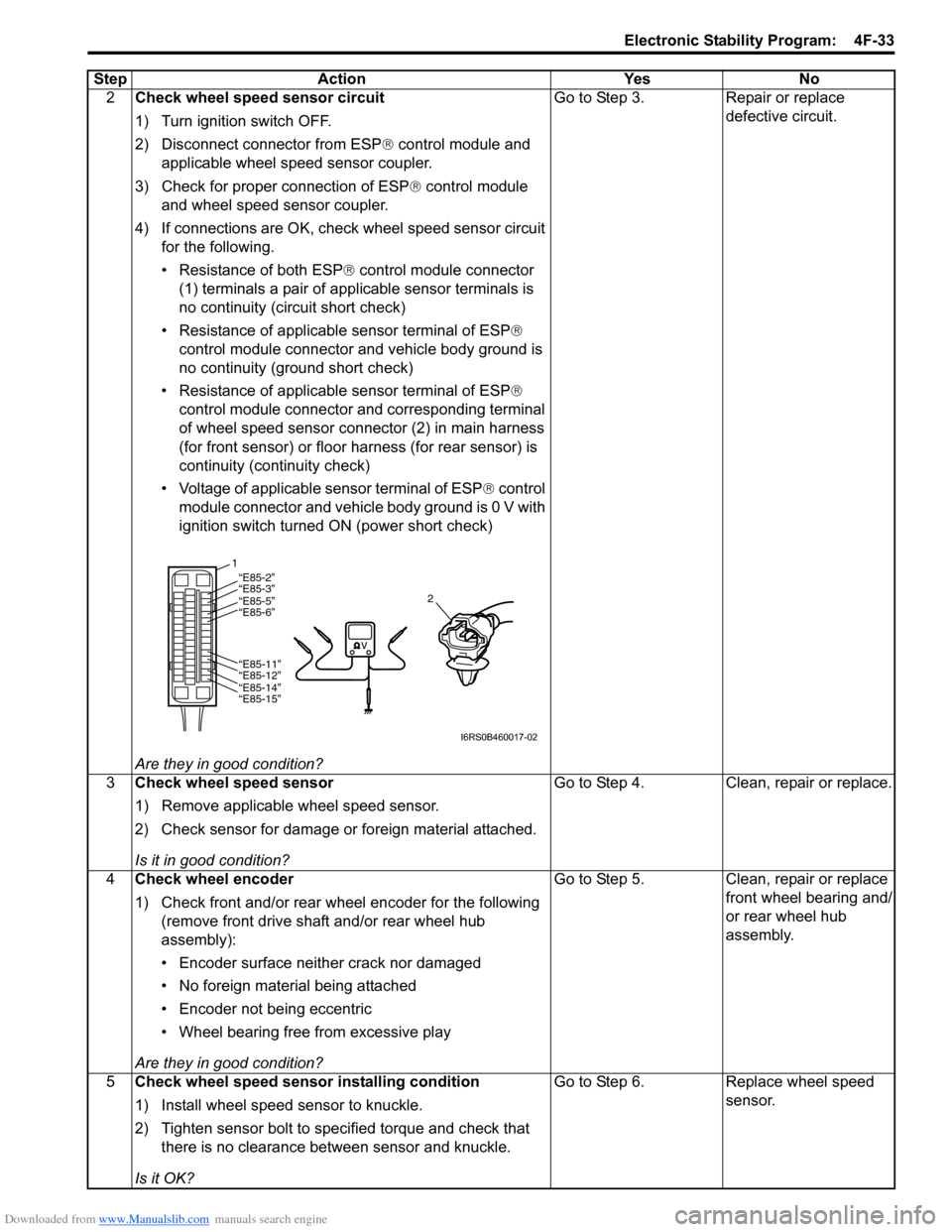
2Check wheel speed sensor circuit
1) Turn ignition switch OFF.
2) Disconnect connector from ESP ® control module and
applicable wheel speed sensor coupler.
3) Check for proper connection of ESP ® control module
and wheel speed sensor coupler.
4) If connections are OK, che ck wheel speed sensor circuit
for the following.
• Resistance of both ESP ® control module connector
(1) terminals a pair of app licable sensor terminals is
no continuity (circuit short check)
• Resistance of applicable sensor terminal of ESP ®
control module connector and vehicle body ground is
no continuity (ground short check)
• Resistance of applicable sensor terminal of ESP ®
control module connector and corresponding terminal
of wheel speed sensor connector (2) in main harness
(for front sensor) or floor harness (for rear sensor) is
continuity (continuity check)
• Voltage of applicable sensor terminal of ESP ® control
module connector and vehicle body ground is 0 V with
ignition switch turned ON (power short check)
Are they in good condition? Go to Step 3. Repair or replace
defective circuit.
3 Check wheel speed sensor
1) Remove applicable wheel speed sensor.
2) Check sensor for damage or foreign material attached.
Is it in good condition? Go to Step 4. Clean, repair or replace.
4 Check wheel encoder
1) Check front and/or rear wheel encoder for the following
(remove front drive shaft and/or rear wheel hub
assembly):
• Encoder surface neither crack nor damaged
• No foreign material being attached
• Encoder not being eccentric
• Wheel bearing free from excessive play
Are they in good condition? Go to Step 5. Clean, repair or replace
front wheel bearing and/
or rear wheel hub
assembly.
5 Check wheel speed sensor installing condition
1) Install wheel speed sensor to knuckle.
2) Tighten sensor bolt to specified torque and check that
there is no clearance between sensor and knuckle.
Is it OK? Go to Step 6. Replace wheel speed
sensor.
Step Action Yes No
1
2“E85-2”“E85-3”“E85-5”
“E85-6”
“E85-11”
“E85-12”
“E85-14”
“E85-15”
I6RS0B460017-02
Page 610 of 1496
Downloaded from www.Manualslib.com manuals search engine 4F-36 Electronic Stability Program:
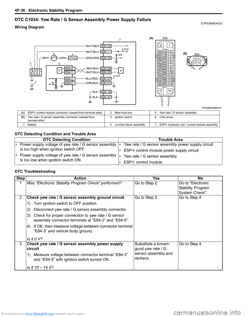
DTC C1034: Yaw Rate / G Sensor Assembly Power Supply FailureS7RS0B4604032
Wiring Diagram
DTC Detecting Condition and Trouble Area
DTC Troubleshooting
[A]E85
161
15
2
3
4
5
6
7
8
9
10
11
12
13
14
17
18
19
20
21
22
23
24
25
26
27
28
29
30
31
3233
34
35
36
37
38
39
40
41
42
43
44
45
46
47 [B]
E84
3
521
46
1
E85-16
E85-47
12V
12VE85-32
E85-1
E85-35GRNWHT
WHT/RED
WHT/BLU
E85-29E85-25
E85-37
E85-31
E84-3
E84-5
RED/BLK
BLK
BLK
WHT/BLKE84-2E84-1 12V
GRN/BLK
BLU/RED
23
5
6 4
7
6
GRN/ORN
I7RS0B460009-01
[A]: ESP ® control module connector (viewed from terminal side ) 2. Main fuse box 5. Yaw rate / G sensor assembly
[B]: Yaw rate / G sensor assembly connector (viewed from harness side) 3. Ignition switch 6. CAN driver
1. Battery 4. Junction block assembly 7. ESP ® hydraulic unit / control module assembly
DTC Detecting Condition Trouble Area
• Power supply voltage of yaw rate / G sensor assembly is too high when ignition switch OFF.
• Power supply voltage of yaw rate / G sensor assembly is too low when ignition switch ON. • Yaw rate / G sensor assembly power supply circuit
• ESP
® control module power supply circuit
• Yaw rate / G sensor assembly
• ESP ® control module
Step Action YesNo
1 Was “Electronic Stability Pr ogram Check” performed? Go to Step 2.Go to “Electronic
Stability Program
System Check”.
2 Check yaw rate / G sensor assembly ground circuit
1) Turn ignition switch to OFF position.
2) Disconnect yaw rate / G se nsor assembly connector.
3) Check for proper connection to yaw rate / G sensor assembly connector terminals at “E84-3” and “E84-5”.
4) If OK, then measure voltage between connector terminal “E84-3” and vehicle body ground.
Is it 0 V? Go to Step 3.
Go to Step 4.
3 Check yaw rate / G sensor assembly power supply
circuit
1) Measure voltage between connector terminal “E84-3”
and “E84-5” with ignition switch turned ON.
Is it 10 – 14 V? Substitute a known-
good yaw rate / G
sensor assembly and
recheck.
Go to Step 4.