drain oil SUZUKI SWIFT 2007 2.G Service Owner's Manual
[x] Cancel search | Manufacturer: SUZUKI, Model Year: 2007, Model line: SWIFT, Model: SUZUKI SWIFT 2007 2.GPages: 1496, PDF Size: 34.44 MB
Page 817 of 1496
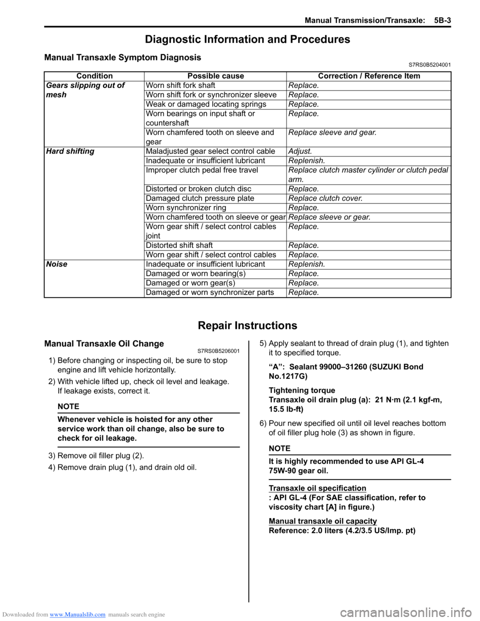
Downloaded from www.Manualslib.com manuals search engine Manual Transmission/Transaxle: 5B-3
Diagnostic Information and Procedures
Manual Transaxle Symptom DiagnosisS7RS0B5204001
Repair Instructions
Manual Transaxle Oil ChangeS7RS0B5206001
1) Before changing or inspecting oil, be sure to stop engine and lift vehicle horizontally.
2) With vehicle lifted up, check oil level and leakage. If leakage exists, correct it.
NOTE
Whenever vehicle is hoisted for any other
service work than oil change, also be sure to
check for oil leakage.
3) Remove oil filler plug (2).
4) Remove drain plug (1), and drain old oil. 5) Apply sealant to thread of drain plug (1), and tighten
it to specified torque.
“A”: Sealant 99000–31260 (SUZUKI Bond
No.1217G)
Tightening torque
Transaxle oil drain plug (a): 21 N·m (2.1 kgf-m,
15.5 lb-ft)
6) Pour new specified oil unt il oil level reaches bottom
of oil filler plug hole (3) as shown in figure.NOTE
It is highly recommended to use API GL-4
75W-90 gear oil.
Transaxle oil specification
: API GL-4 (For SAE classification, refer to
viscosity chart [A] in figure.)
Manual transaxle oil capacity
Reference: 2.0 liters (4.2/3.5 US/Imp. pt)
Condition Possible cause Correction / Reference Item
Gears slipping out of
mesh Worn shift fork shaft
Replace.
Worn shift fork or synchronizer sleeve Replace.
Weak or damaged locating springs Replace.
Worn bearings on input shaft or
countershaft Replace.
Worn chamfered tooth on sleeve and
gear Replace sleeve and gear.
Hard shifting Maladjusted gear select control cable Adjust.
Inadequate or insufficient lubricant Replenish.
Improper clutch pedal free travel Replace clutch master cylinder or clutch pedal
arm.
Distorted or broken clutch disc Replace.
Damaged clutch pressure plate Replace clutch cover.
Worn synchronizer ring Replace.
Worn chamfered tooth on sleeve or gear Replace sleeve or gear.
Worn gear shift / select control cables
joint Replace.
Distorted shift shaft Replace.
Worn gear shift / select control cables Replace.
Noise Inadequate or insufficient lubricant Replenish.
Damaged or worn bearing(s) Replace.
Damaged or worn gear(s) Replace.
Damaged or worn synchronizer parts Replace.
Page 818 of 1496
Downloaded from www.Manualslib.com manuals search engine 5B-4 Manual Transmission/Transaxle:
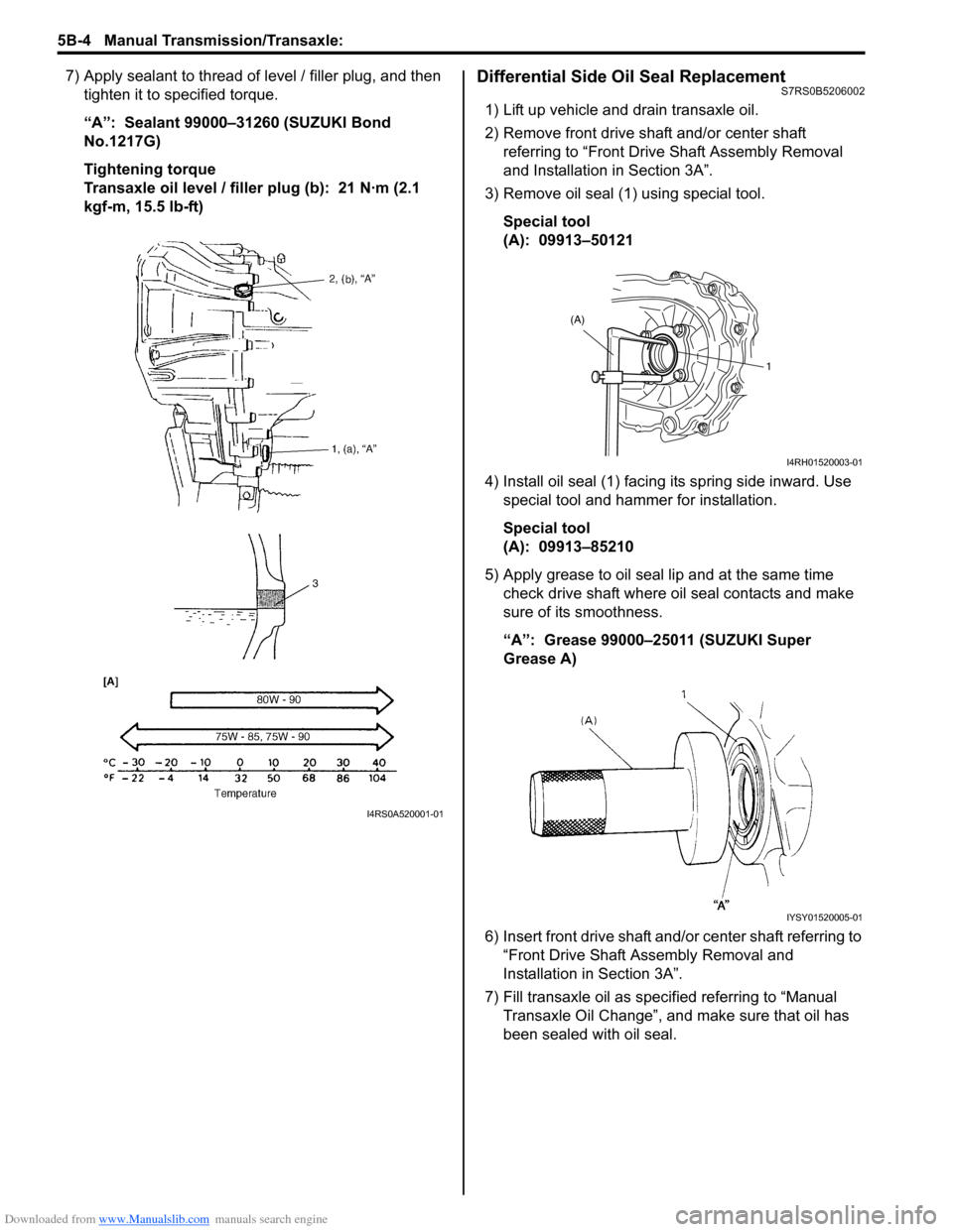
7) Apply sealant to thread of level / filler plug, and then
tighten it to specified torque.
“A”: Sealant 99000–31260 (SUZUKI Bond
No.1217G)
Tightening torque
Transaxle oil level / filler plug (b): 21 N·m (2.1
kgf-m, 15.5 lb-ft)Differential Side Oil Seal ReplacementS7RS0B5206002
1) Lift up vehicle and drain transaxle oil.
2) Remove front drive shaft and/or center shaft referring to “Front Driv e Shaft Assembly Removal
and Installation in Section 3A”.
3) Remove oil seal (1) using special tool.
Special tool
(A): 09913–50121
4) Install oil seal (1) facing its spring side inward. Use special tool and hammer for installation.
Special tool
(A): 09913–85210
5) Apply grease to oil seal lip and at the same time check drive shaft where oil seal contacts and make
sure of its smoothness.
“A”: Grease 99000–25011 (SUZUKI Super
Grease A)
6) Insert front drive shaft and/or center shaft referring to “Front Drive Shaft A ssembly Removal and
Installation in Section 3A”.
7) Fill transaxle oil as specified referring to “Manual Transaxle Oil Change”, and make sure that oil has
been sealed with oil seal.
I4RS0A520001-01
(A)
1
I4RH01520003-01
IYSY01520005-01
Page 823 of 1496
Downloaded from www.Manualslib.com manuals search engine Manual Transmission/Transaxle: 5B-9
Manual Transaxle Unit Dismounting and
Remounting
S7RS0B5206009
Dismounting1) Drain coolant and transaxle oil.
2) Remove coolant reservoir with reservoir hose.
3) Remove battery and tray.
4) Remove air cleaner case and resonator.
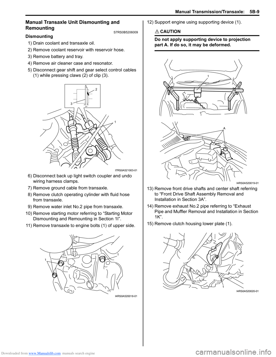
5) Disconnect gear shift and gear select control cables (1) while pressing claws (2) of clip (3).
6) Disconnect back up light switch coupler and undo wiring harness clamps.
7) Remove ground cable from transaxle.
8) Remove clutch operating cylinder with fluid hose from transaxle.
9) Remove water inlet No.2 pipe from transaxle.
10) Remove starting motor re ferring to “Starting Motor
Dismounting and Remounting in Section 1I”.
11) Remove transaxle to engine bolts (1) of upper side. 12) Support engine using supporting device (1).
CAUTION!
Do not apply supporting device to projection
part A. If do so, it may be deformed.
13) Remove front drive shafts and center shaft referring
to “Front Drive Shaft Assembly Removal and
Installation in Section 3A”.
14) Remove exhaust No.2 pipe referring to “Exhaust Pipe and Muffler Removal a nd Installation in Section
1K”.
15) Remove clutch housing lower plate (1).
1
2
3
I7RS0A521003-01
1
1
I4RS0A520018-01
1
A
I4RS0A520019-01
1I4RS0A520020-01
Page 827 of 1496
Downloaded from www.Manualslib.com manuals search engine Manual Transmission/Transaxle: 5B-13
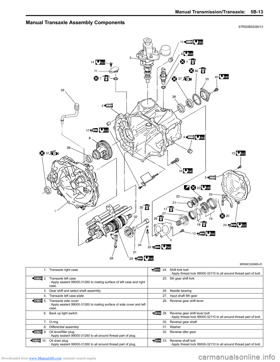
Manual Transaxle Assembly ComponentsS7RS0B5206013
I6RS0C520005-01
1. Transaxle right case 24. Shift fork bolt
: Apply thread lock 99000-32110 to all around thread part of bolt.
2. Transaxle left case : Apply sealant 99000-31260 to mating surface of left case and right
case. 25. 5th gear shift fork
3. Gear shift and select shaft assembly 26. Needle bearing
4. Transaxle left case plate 27. Input shaft 5th gear
5. Transaxle side cover : Apply sealant 99000-31260 to mating surface of side cover and left
case. 28. Reverse gear shift lever
6. Back up light switch 29. Reverse gear shift lever bolt
: Apply thread lock 99000-32110 to all around thread part of bolt.
7. O-ring 30. Reverse gear shaft
8. Differential assembly 31. Washer
9. Oil level/filler plug : Apply sealant 99000-31260 to all around thread part of plug. 32. Reverse idler gear
10. Oil drain plug : Apply sealant 99000-31260 to all around thread part of plug. 33. Reverse shaft bolt
: Apply thread lock 99000-32110 to all around thread part of bolt.
Page 849 of 1496
Downloaded from www.Manualslib.com manuals search engine Manual Transmission/Transaxle: 5B-35
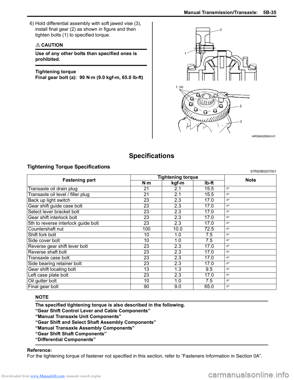
6) Hold differential assembly with soft jawed vise (3),
install final gear (2) as shown in figure and then
tighten bolts (1) to specified torque.
CAUTION!
Use of any other bolts than specified ones is
prohibited.
Tightening torque
Final gear bolt (a): 90 N·m (9.0 kgf-m, 65.0 lb-ft)
Specifications
Tightening Torque SpecificationsS7RS0B5207001
NOTE
The specified tightening torque is also described in the following.
“Gear Shift Control Leve r and Cable Components”
“Manual Transaxle Unit Components”
“Gear Shift and Select Shaft Assembly Components”
“Manual Transaxle Assembly Components”
“Gear Shift Shaft Components”
“Differential Components”
Reference:
For the tightening torque of fastener not specified in this section, refer to “Fasteners Information in Section 0A”.
I4RS0A520043-01
Fastening part Tightening torque
Note
N ⋅mkgf-mlb-ft
Transaxle oil drain plug 21 2.1 15.5 �)
Transaxle oil level / filler plug 21 2.1 15.5 �)
Back up light switch 23 2.3 17.0 �)
Gear shift guide case bolt 23 2.3 17.0 �)
Select lever bracket bolt 23 2.3 17.0 �)
Gear shift interlock bolt 23 2.3 17.0 �)
5th to reverse interlock guide bolt 23 2.3 17.0 �)
Countershaft nut 100 10.0 72.5 �)
Shift fork bolt 10 1.0 7.5 �)
Side cover bolt 10 1.0 7.5 �)
Reverse gear shift lever bolt 23 2.3 17.0 �)
Reverse shaft bolt 23 2.3 17.0 �)
Transaxle case bolt 23 2.3 17.0 �)
Side bearing retainer bolt 23 2.3 17.0 �)
Gear shift locating bolt 13 1.3 9.5 �)
Left case plate bolt 23 2.3 17.0 �)
Oil gutter bolt 10 1.0 7.5 �)
Final gear bolt 90 9.0 65.0 �)
Page 950 of 1496
Downloaded from www.Manualslib.com manuals search engine 7B-2 Air Conditioning System: Manual Type
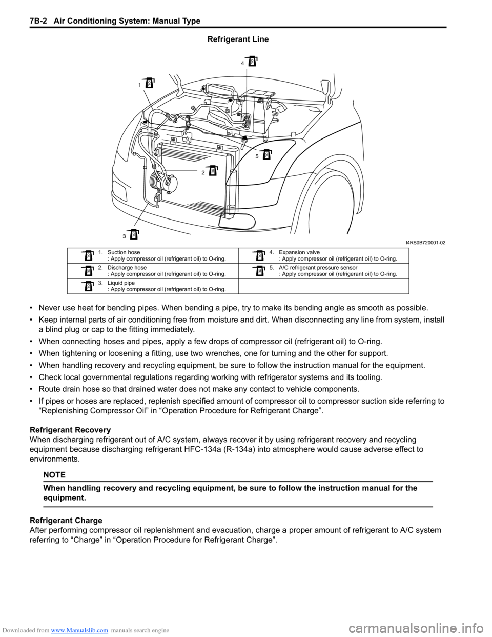
Refrigerant Line
• Never use heat for bending pipes. When bending a pipe , try to make its bending angle as smooth as possible.
• Keep internal parts of air conditioning free from moistu re and dirt. When disconnecting any line from system, install
a blind plug or cap to the fitting immediately.
• When connecting hoses and pipes, apply a few drops of compressor oil (refrigerant oil) to O-ring.
• When tightening or loosening a fitting, use two wrenches, one for turning and the other for support.
• When handling recovery and recycling equipment, be sure to follow the instruction manual for the equipment.
• Check local governmental regulations regarding working with refrigerator systems and its tooling.
• Route drain hose so that drained water does not make any contact to vehicle components.
• If pipes or hoses are replaced, replenish specified amount of compressor oil to compre ssor suction side referring to
“Replenishing Compressor Oil” in “Operation Procedure for Refrigerant Charge”.
Refrigerant Recovery
When discharging refrigerant out of A/C system, always recover it by using refrigerant recovery and recycling
equipment because discharging refrigerant HFC-134a (R-1 34a) into atmosphere would cause adverse effect to
environments.
NOTE
When handling recovery and recycling equipment, be sure to follow the instruction manual for the
equipment.
Refrigerant Charge
After performing compressor oil replenishment and evacuat ion, charge a proper amount of refrigerant to A/C system
referring to “Charge” in “Operation Procedure for Refrigerant Charge”.
3
1
2
4
5
I4RS0B720001-02
1. Suction hose : Apply compressor oil (refrigerant oil) to O-ring. 4. Expansion valve
: Apply compressor oil (refrigerant oil) to O-ring.
2. Discharge hose : Apply compressor oil (refrigerant oil) to O-ring. 5. A/C refrigerant pressure sensor
: Apply compressor oil (refrigerant oil) to O-ring.
3. Liquid pipe : Apply compressor oil (refrigerant oil) to O-ring.
Page 956 of 1496
Downloaded from www.Manualslib.com manuals search engine 7B-8 Air Conditioning System: Manual Type
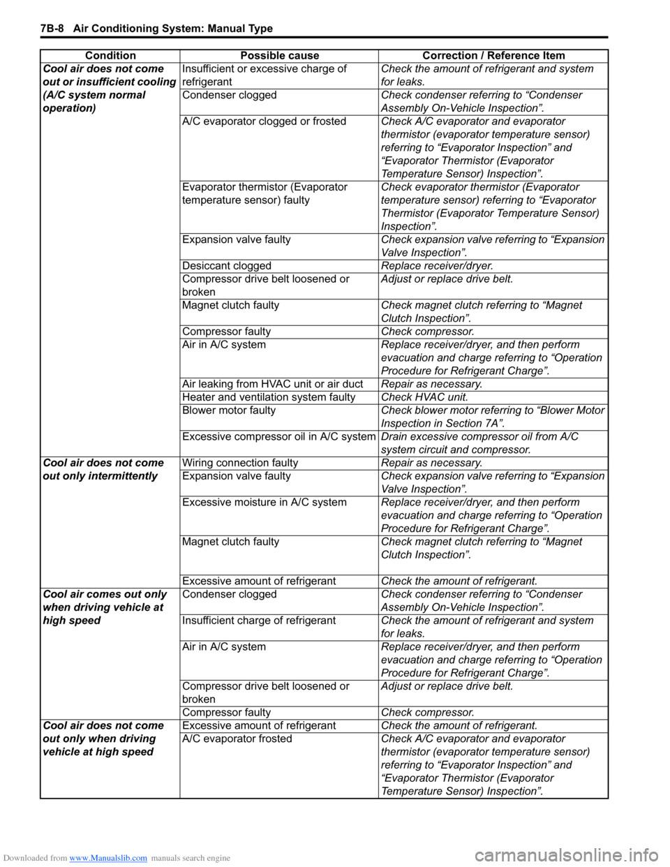
Cool air does not come
out or insufficient cooling
(A/C system normal
operation)Insufficient or excessive charge of
refrigerant
Check the amount of refrigerant and system
for leaks.
Condenser clogged Check condenser referring to “Condenser
Assembly On-Vehicle Inspection”.
A/C evaporator clogged or frosted Check A/C evaporator and evaporator
thermistor (evaporator temperature sensor)
referring to “Evaporator Inspection” and
“Evaporator Thermistor (Evaporator
Temperature Sensor) Inspection”.
Evaporator thermistor (Evaporator
temperature sensor) faulty Check evaporator thermistor (Evaporator
temperature sensor) referring to “Evaporator
Thermistor (Evaporator Temperature Sensor)
Inspection”.
Expansion valve faulty Check expansion valve referring to “Expansion
Valve Inspection”.
Desiccant clogged Replace receiver/dryer.
Compressor drive belt loosened or
broken Adjust or replace drive belt.
Magnet clutch faulty Check magnet clutch referring to “Magnet
Clutch Inspection”.
Compressor faulty Check compressor.
Air in A/C system Replace receiver/dryer, and then perform
evacuation and charge referring to “Operation
Procedure for Refrigerant Charge”.
Air leaking from HVAC unit or air duct Repair as necessary.
Heater and ventilation system faulty Check HVAC unit.
Blower motor faulty Check blower motor referring to “Blower Motor
Inspection in Section 7A”.
Excessive compressor oil in A/C system Drain excessive compressor oil from A/C
system circuit and compressor.
Cool air does not come
out only intermittently Wiring connection faulty
Repair as necessary.
Expansion valve faulty Check expansion valve referring to “Expansion
Valve Inspection”.
Excessive moisture in A/C system Replace receiver/dryer, and then perform
evacuation and charge referring to “Operation
Procedure for Refrigerant Charge”.
Magnet clutch faulty Check magnet clutch referring to “Magnet
Clutch Inspection”.
Excessive amount of refrigerant Check the amount of refrigerant.
Cool air comes out only
when driving vehicle at
high speed Condenser clogged
Check condenser referring to “Condenser
Assembly On-Vehicle Inspection”.
Insufficient charge of refrigerant Check the amount of refrigerant and system
for leaks.
Air in A/C system Replace receiver/dryer, and then perform
evacuation and charge referring to “Operation
Procedure for Refrigerant Charge”.
Compressor drive belt loosened or
broken Adjust or replace drive belt.
Compressor faulty Check compressor.
Cool air does not come
out only when driving
vehicle at high speed Excessive amount of refrigerant
Check the amount of refrigerant.
A/C evaporator frosted Check A/C evaporator and evaporator
thermistor (evaporator temperature sensor)
referring to “Evaporator Inspection” and
“Evaporator Thermistor (Evaporator
Temperature Sensor) Inspection”.
Condition Possible cause Correction / Reference Item
Page 965 of 1496
Downloaded from www.Manualslib.com manuals search engine Air Conditioning System: Manual Type 7B-17
NOTE
• After recovering refrigerant from system, the amount of removed compressor oil must be measured
for replenishing compressor oil.
• When handling recovery and recycling equipment, be sure to follow the instruction manual for the equipment.
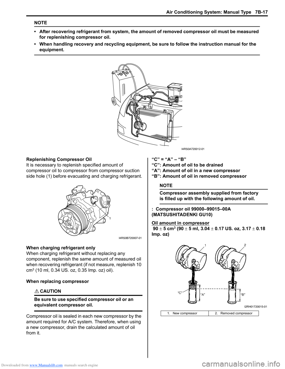
Replenishing Compressor Oil
It is necessary to replenish specified amount of
compressor oil to compressor from compressor suction
side hole (1) before evacuating and charging refrigerant.
When charging refrigerant only
When charging refrigerant without replacing any
component, replenish the same amount of measured oil
when recovering refrigerant (if not measure, replenish 10
cm
3 (10 ml, 0.34 US. oz, 0.35 Imp. oz) oil).
When replacing compressor
CAUTION!
Be sure to use specified compressor oil or an
equivalent compressor oil.
Compressor oil is sealed in each new compressor by the
amount required for A/C system. Therefore, when using
a new compressor, drain the calculated amount of oil
from it. “C” = “A” – “B”
“C”: Amount of oil to be drained
“A”: Amount of oil in a new compressor
“B”: Amount of oil in removed compressor
NOTE
Compressor assembly su
pplied from factory
is filled up with the following amount of oil.
: Compressor oil 99000–99015–00A
(MATSUSHITADENKI GU10)
Oil amount in compressor
90 ± 5 cm3 (90 ± 5 ml, 3.04 ± 0.17 US. oz, 3.17 ± 0.18
Imp. oz)
I4RS0A720012-01
1
I4RS0B720007-01
1. New compressor 2. Removed compressor
I2RH01720015-01
Page 972 of 1496

Downloaded from www.Manualslib.com manuals search engine 7B-24 Air Conditioning System: Manual Type
HVAC Unit Removal and InstallationS7RS0B7216006
Removal1) Disconnect negative (–) cable from battery.
2) Disable air bag system referring to “Disabling Air Bag System in Section 8B”.
3) Recover refrigerant from A/C system with recovery and recycling equipment referring to “Recovery” in
“Operation Procedure for Refrigerant Charge”.
4) Remove cowl top panel referring to “Cowl Top Components in Section 9K”.
5) Drain engine coolant, and then disconnect heater hoses (1) from HVAC unit (2).
6) Remove instrument panel from vehicle body referring to “Audio Unit Re moval and Installation in
Section 9C”.
7) Loosen suction hose and liquid pipe bolt (4).
8) Remove nuts (3).
9) Remove HVAC unit from vehicle body. Installation
Reverse removal procedure noting the following
instructions.
• Replenish specified amount of compressor oil to
compressor suction side referring to “Replenishing
Compressor Oil” in “Operation Procedure for
Refrigerant Charge”.
• Install the padding (1) to the installation hole uniformly.
• Evacuate and charge the A/C system referring to “Evacuation” and “Charge” in “Operation Procedure
for Refrigerant Charge”.
• Adjust control cables referr ing to “HVAC Control Unit
Removal and Installati on in Section 7A”.
• Enable air bag system referring to “Enabling Air Bag System in Section 8B”.
Evaporator InspectionS7RS0B7216007
Check the followings.
• Clog of A/C evaporator fins.If any clogs are found, A/C evaporator fins should be
washed with water, and then should be dried with
compressed air.
• A/C evaporator fins for leakage and breakage. If any defects are found, repair or replace A/C
evaporator.
• A/C evaporator fittings for leakage. If any defects are found, repair or replace A/C
evaporator.
2. Blower upper case 8. Temperature control door assembly 14. Temperature control lever 20. Packing
3. Air intake control actuator 9. Blower motor resistor 15. Airflow control lever21. Filter cover (if equipped)
4. HVAC Air filter (if equipped) 10. Blower lower case 16. Evaporator22. Drain hose
5. Heater unit upper case 11. Blower motor 17. O-ring23. Cable lock clamp
6. Foot duct 12. Heater unit lower case 18. Expansion valve: Do not reuse.
3
2
3
3
1
4
I4RS0B720009-01
1
I4RS0B720010-01
Page 989 of 1496
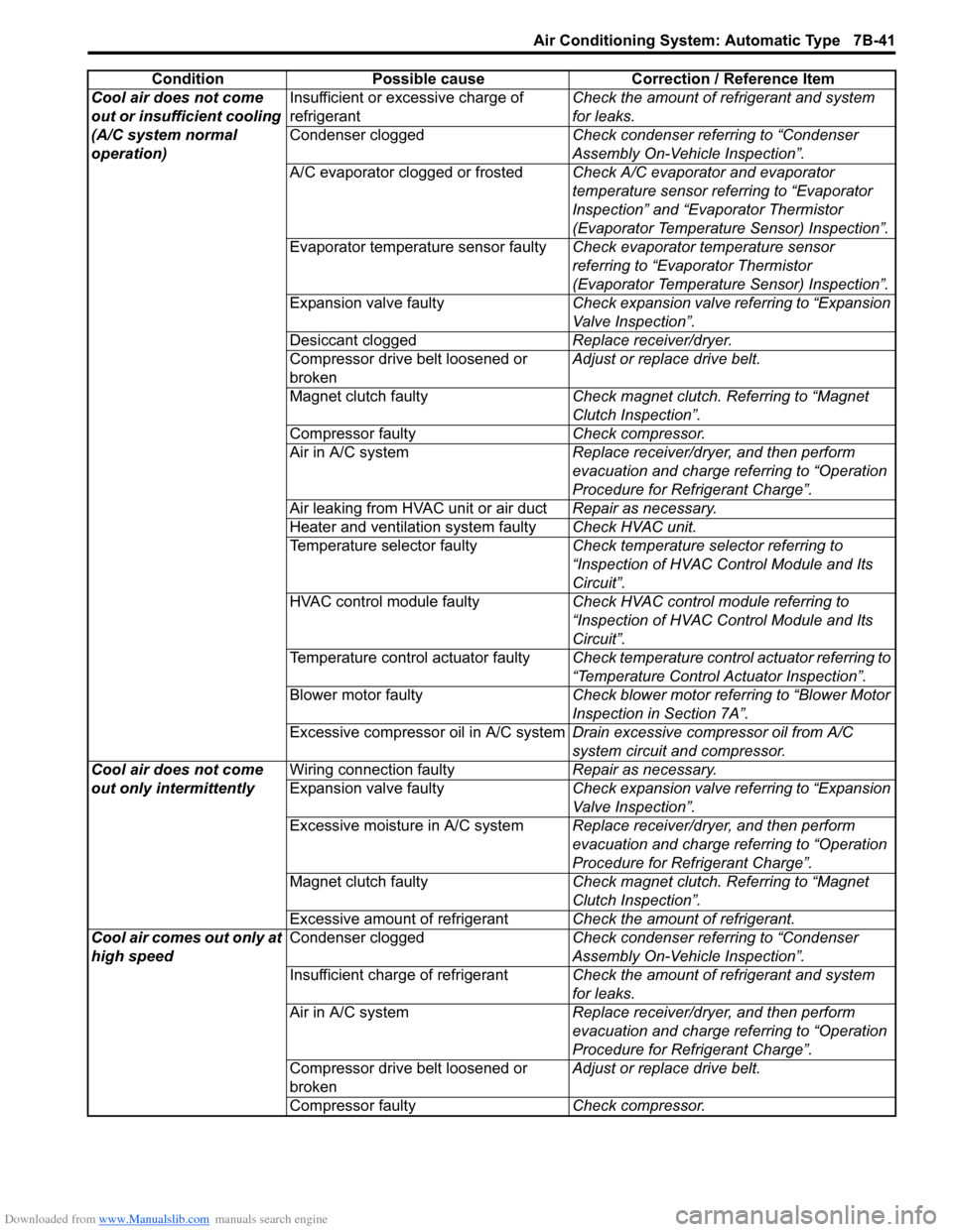
Downloaded from www.Manualslib.com manuals search engine Air Conditioning System: Automatic Type 7B-41
Cool air does not come
out or insufficient cooling
(A/C system normal
operation)Insufficient or excessive charge of
refrigerant
Check the amount of refrigerant and system
for leaks.
Condenser clogged Check condenser referring to “Condenser
Assembly On-Vehicle Inspection”.
A/C evaporator clogged or frosted Check A/C evaporator and evaporator
temperature sensor referring to “Evaporator
Inspection” and “Evaporator Thermistor
(Evaporator Temperature Sensor) Inspection”.
Evaporator temperature sensor faulty Check evaporator temperature sensor
referring to “Evaporator Thermistor
(Evaporator Temperature Sensor) Inspection”.
Expansion valve faulty Check expansion valve referring to “Expansion
Valve Inspection”.
Desiccant clogged Replace receiver/dryer.
Compressor drive belt loosened or
broken Adjust or replace drive belt.
Magnet clutch faulty Check magnet clutch. Referring to “Magnet
Clutch Inspection”.
Compressor faulty Check compressor.
Air in A/C system Replace receiver/dryer, and then perform
evacuation and charge referring to “Operation
Procedure for Refrigerant Charge”.
Air leaking from HVAC unit or air duct Repair as necessary.
Heater and ventilation system faulty Check HVAC unit.
Temperature selector faulty Check temperature selector referring to
“Inspection of HVAC Control Module and Its
Circuit”.
HVAC control module faulty Check HVAC control module referring to
“Inspection of HVAC Control Module and Its
Circuit”.
Temperature control actuator faulty Check temperature control actuator referring to
“Temperature Control Actuator Inspection”.
Blower motor faulty Check blower motor referring to “Blower Motor
Inspection in Section 7A”.
Excessive compressor oil in A/C system Drain excessive compressor oil from A/C
system circuit and compressor.
Cool air does not come
out only intermittently Wiring connection faulty
Repair as necessary.
Expansion valve faulty Check expansion valve referring to “Expansion
Valve Inspection”.
Excessive moisture in A/C system Replace receiver/dryer, and then perform
evacuation and charge referring to “Operation
Procedure for Refrigerant Charge”.
Magnet clutch faulty Check magnet clutch. Referring to “Magnet
Clutch Inspection”.
Excessive amount of refrigerant Check the amount of refrigerant.
Cool air comes out only at
high speed Condenser clogged
Check condenser referring to “Condenser
Assembly On-Vehicle Inspection”.
Insufficient charge of refrigerant Check the amount of refrigerant and system
for leaks.
Air in A/C system Replace receiver/dryer, and then perform
evacuation and charge referring to “Operation
Procedure for Refrigerant Charge”.
Compressor drive belt loosened or
broken Adjust or replace drive belt.
Compressor faulty Check compressor.
Condition Possible cause Correction / Reference Item