hoses SUZUKI SWIFT 2007 2.G Service Owner's Manual
[x] Cancel search | Manufacturer: SUZUKI, Model Year: 2007, Model line: SWIFT, Model: SUZUKI SWIFT 2007 2.GPages: 1496, PDF Size: 34.44 MB
Page 373 of 1496
Downloaded from www.Manualslib.com manuals search engine Engine Cooling System: 1F-10
Radiator Cooling Fan Removal and InstallationS7RS0B1606011
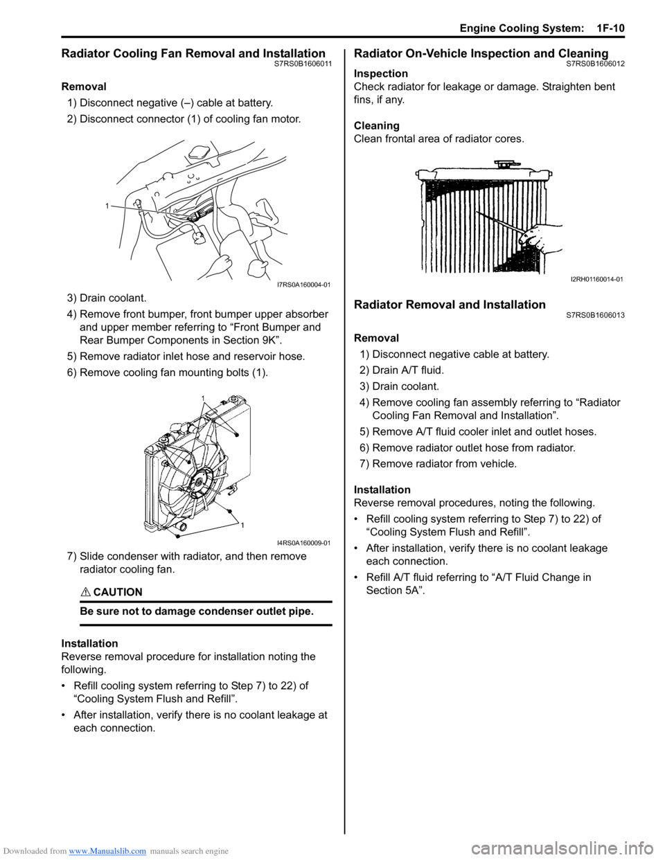
Removal1) Disconnect negative (–) cable at battery.
2) Disconnect connector (1) of cooling fan motor.
3) Drain coolant.
4) Remove front bumper, front bumper upper absorber and upper member referring to “Front Bumper and
Rear Bumper Componen ts in Section 9K”.
5) Remove radiator inlet hose and reservoir hose.
6) Remove cooling fan mounting bolts (1).
7) Slide condenser with radiator, and then remove radiator cooling fan.
CAUTION!
Be sure not to damage condenser outlet pipe.
Installation
Reverse removal procedure for installation noting the
following.
• Refill cooling system referring to Step 7) to 22) of “Cooling System Fl ush and Refill”.
• After installation, verify there is no coolant leakage at each connection.
Radiator On-Vehicle Inspection and CleaningS7RS0B1606012
Inspection
Check radiator for leakage or damage. Straighten bent
fins, if any.
Cleaning
Clean frontal area of radiator cores.
Radiator Removal and InstallationS7RS0B1606013
Removal
1) Disconnect negative cable at battery.
2) Drain A/T fluid.
3) Drain coolant.
4) Remove cooling fan assemb ly referring to “Radiator
Cooling Fan Removal and Installation”.
5) Remove A/T fluid cooler inlet and outlet hoses.
6) Remove radiator outlet hose from radiator.
7) Remove radiator from vehicle.
Installation
Reverse removal procedures, noting the following.
• Refill cooling system referrin g to Step 7) to 22) of
“Cooling System Flush and Refill”.
• After installation, verify there is no coolant leakage each connection.
• Refill A/T fluid referring to “A/T Fluid Change in
Section 5A”.
1
I7RS0A160004-01
I4RS0A160009-01
I2RH01160014-01
Page 377 of 1496
Downloaded from www.Manualslib.com manuals search engine Fuel System: 1G-2
Fuel Pump DescriptionS7RS0B1701003
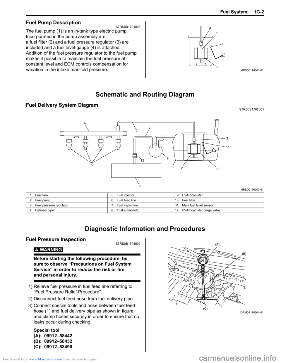
The fuel pump (1) is an in-tank type electric pump.
Incorporated in the pump assembly are;
a fuel filter (2) and a fuel pressure regulator (3) are
included and a fuel level gauge (4) is attached.
Addition of the fuel pressure regulator to the fuel pump
makes it possible to mainta in the fuel pressure at
constant level and ECM controls compensation for
variation in the intake manifold pressure.
Schematic and Routing Diagram
Fuel Delivery System DiagramS7RS0B1702001
Diagnostic Information and Procedures
Fuel Pressure InspectionS7RS0B1704001
WARNING!
Before starting the following procedure, be
sure to observe “Precautions on Fuel System
Service” in order to reduce the risk or fire
and personal injury.
1) Relieve fuel pressure in fuel feed line referring to
“Fuel Pressure Relief Procedure”.
2) Disconnect fuel feed hose from fuel delivery pipe.
3) Connect special tools and hose between fuel feed hose (1) and fuel delivery pipe as shown in figure,
and clamp hoses securely in order to ensure that no
leaks occur during checking.
Special tool
(A): 09912–58442
(B): 09912–58432
(C): 09912–58490
1
3
2
4
I6RS0C170001-01
4
6 7
8
12
2 3
11
10
5
1
9
I6RS0C170002-01
1. Fuel tank
5. Fuel injector9. EVAP canister
2. Fuel pump 6. Fuel feed line10. Fuel filter
3. Fuel pressure regulator 7. Fuel vapor line 11. Main fuel level sensor
4. Delivery pipe 8. Intake manifold12. EVAP canister purge valve
1
(C) (B)
(A)
I3RM0A170004-01
Page 383 of 1496
Downloaded from www.Manualslib.com manuals search engine Fuel System: 1G-8
Installation1) Install clamps to marked location on pipes. If clamp is deformed, its claw is bent or broken, replace it with
new one.
2) Install pipes with pipe clamps to vehicle.
3) Connect fuel hoses and pipes to each pipe referring to “Fuel Hose Disconnecting and Reconnecting”.
4) Connect negative cable at battery.
5) With engine OFF, turn igniti on switch to ON position
and check for fuel leaks.
Fuel Injector On-Vehicle InspectionS7RS0B1706007
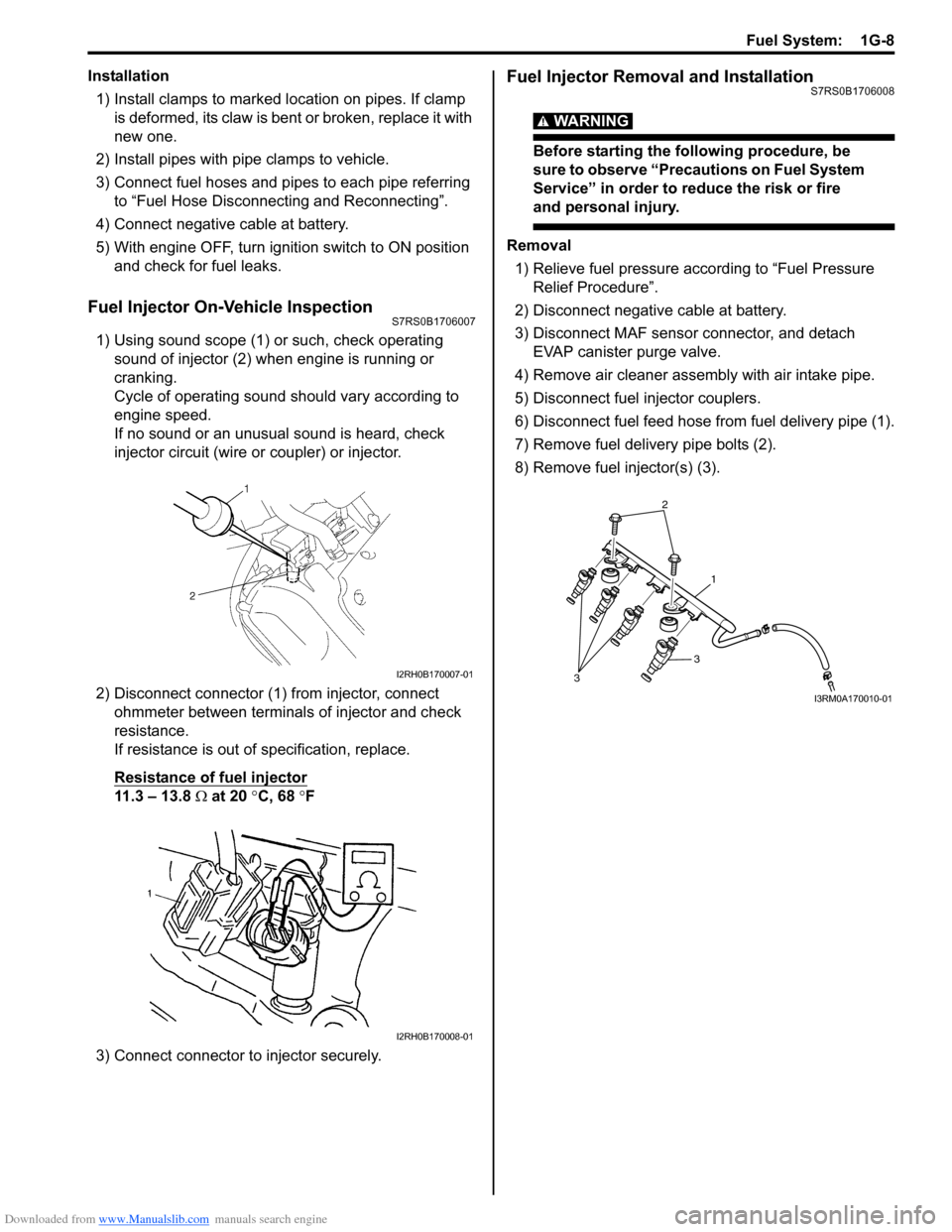
1) Using sound scope (1) or such, check operating sound of injector (2) when engine is running or
cranking.
Cycle of operating sound should vary according to
engine speed.
If no sound or an unusual sound is heard, check
injector circuit (wire or coupler) or injector.
2) Disconnect connector (1) from injector, connect ohmmeter between terminals of injector and check
resistance.
If resistance is out of specification, replace.
Resistance of fuel injector
11.3 – 13.8 Ω at 20 °C, 68 °F
3) Connect connector to injector securely.
Fuel Injector Removal and InstallationS7RS0B1706008
WARNING!
Before starting the following procedure, be
sure to observe “Precautions on Fuel System
Service” in order to reduce the risk or fire
and personal injury.
Removal 1) Relieve fuel pressure according to “Fuel Pressure Relief Procedure”.
2) Disconnect negative cable at battery.
3) Disconnect MAF sensor connector, and detach EVAP canister purge valve.
4) Remove air cleaner assembly with air intake pipe.
5) Disconnect fuel injector couplers.
6) Disconnect fuel feed hose from fuel delivery pipe (1).
7) Remove fuel delivery pipe bolts (2).
8) Remove fuel injector(s) (3).
I2RH0B170007-01
I2RH0B170008-01
2
1
3
3
I3RM0A170010-01
Page 387 of 1496
Downloaded from www.Manualslib.com manuals search engine Fuel System: 1G-12
Fuel Tank Inlet Valve InspectionS7RS0B1706012
WARNING!
Before starting the following procedure, be
sure to observe “Precautions on Fuel System
Service” in order to reduce the risk or fire
and personal injury.
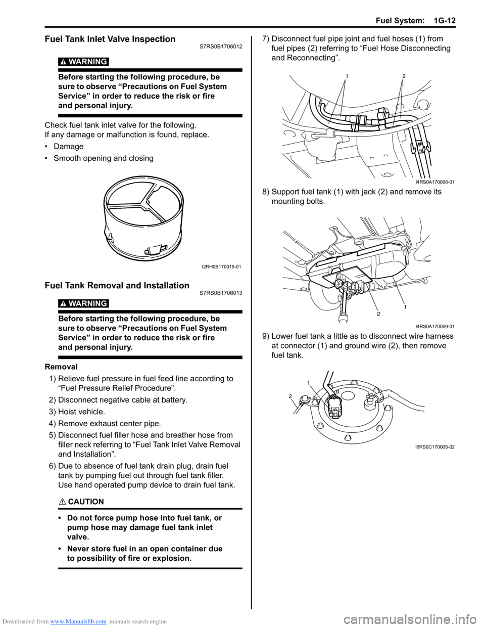
Check fuel tank inlet valve for the following.
If any damage or malfunction is found, replace.
•Damage
• Smooth opening and closing
Fuel Tank Removal and InstallationS7RS0B1706013
WARNING!
Before starting the following procedure, be
sure to observe “Precautions on Fuel System
Service” in order to reduce the risk or fire
and personal injury.
Removal1) Relieve fuel pressure in fuel feed line according to
“Fuel Pressure Relief Procedure”.
2) Disconnect negative cable at battery.
3) Hoist vehicle.
4) Remove exhaust center pipe.
5) Disconnect fuel filler hose and breather hose from
filler neck referring to “Fue l Tank Inlet Valve Removal
and Installation”.
6) Due to absence of fuel tank drain plug, drain fuel tank by pumping fuel out through fuel tank filler.
Use hand operated pump device to drain fuel tank.
CAUTION!
• Do not force pump hose into fuel tank, or pump hose may damage fuel tank inlet
valve.
• Never store fuel in an open container due to possibility of fire or explosion.
7) Disconnect fuel pipe joint and fuel hoses (1) from fuel pipes (2) referring to “Fuel Hose Disconnecting
and Reconnecting”.
8) Support fuel tank (1) with jack (2) and remove its mounting bolts.
9) Lower fuel tank a little as to disconnect wire harness at connector (1) and ground wire (2), then remove
fuel tank.
I2RH0B170019-01
12
I4RS0A170008-01
12
I4RS0A170009-01
1
2
I6RS0C170005-02
Page 388 of 1496
Downloaded from www.Manualslib.com manuals search engine 1G-13 Fuel System:
Installation
CAUTION!
• When connecting joint, clean outside surfaces of pipe where joint is to be
inserted, push joint into pipe till joint lock
clicks and check to ensure that pipes are
connected securely, or fuel leak may
occur.
• Never let the fuel hoses touch the ABS sensor harness (if equipped).
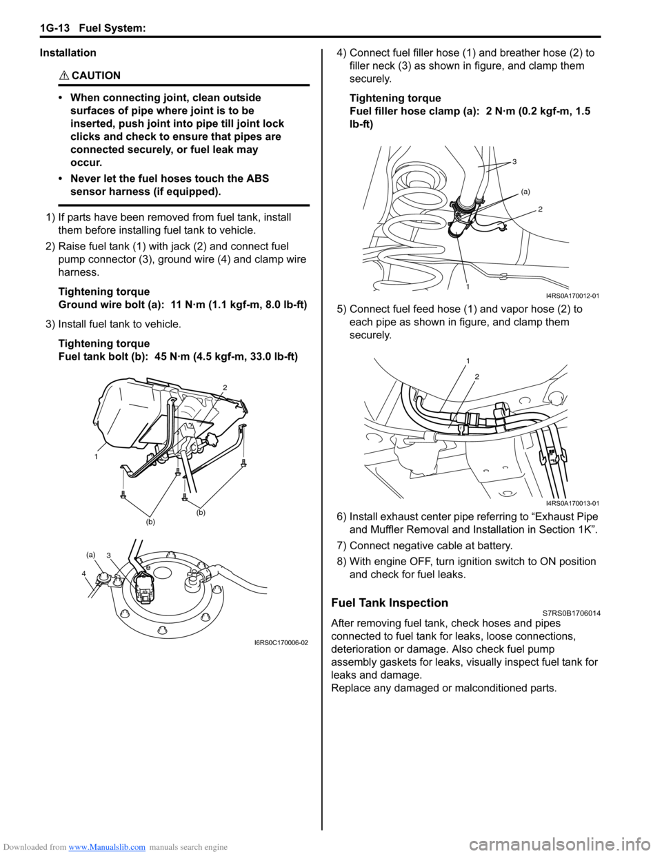
1) If parts have been removed from fuel tank, install them before installing fuel tank to vehicle.
2) Raise fuel tank (1) with jack (2) and connect fuel pump connector (3), ground wire (4) and clamp wire
harness.
Tightening torque
Ground wire bolt (a): 11 N·m (1.1 kgf-m, 8.0 lb-ft)
3) Install fuel tank to vehicle. Tightening torque
Fuel tank bolt (b): 45 N·m (4.5 kgf-m, 33.0 lb-ft) 4) Connect fuel filler hose (1
) and breather hose (2) to
filler neck (3) as shown in figure, and clamp them
securely.
Tightening torque
Fuel filler hose clamp (a): 2 N·m (0.2 kgf-m, 1.5
lb-ft)
5) Connect fuel feed hose (1) and vapor hose (2) to each pipe as shown in figure, and clamp them
securely.
6) Install exhaust center pipe referring to “Exhaust Pipe and Muffler Removal and Installation in Section 1K”.
7) Connect negative cable at battery.
8) With engine OFF, turn ignition switch to ON position and check for fuel leaks.
Fuel Tank InspectionS7RS0B1706014
After removing fuel tank, check hoses and pipes
connected to fuel tank for leaks, loose connections,
deterioration or damage. Also check fuel pump
assembly gaskets for leaks, visually inspect fuel tank for
leaks and damage.
Replace any damaged or malconditioned parts.
(b)(b)
1
2
3
4
(a)
I6RS0C170006-02
1
2
(a)
3
I4RS0A170012-01
1
2
I4RS0A170013-01
Page 389 of 1496
Downloaded from www.Manualslib.com manuals search engine Fuel System: 1G-14
Fuel Tank Purging ProcedureS7RS0B1706015
WARNING!
• Before starting the following procedure, be sure to observe “Precautions on Fuel
System Service” in order to reduce the risk
or fire and personal injury.
• This purging procedure will not remove all fuel vapor.
Do not attempt any repair on tank using
heat of flame as an explosion resulting in
personal injury could occur.
CAUTION!
Never remain water in fu el tank after washing,
or fuel tank inside will get corrosion.
The following procedure are used for purging fuel tank.
1) After removing fuel tank, remove all hoses, pipes and fuel pump assembly from fuel tank.
2) Drain all remaining fuel from tank.
3) Place fuel tank to flushing area.
4) Fill tank with warm water or tap water, and agitate
vigorously and drain. Repeat this washing until
inside of tank is clean. Replace tank if its inside is
rusty.
5) Completely flush out rema ining water after washing.
Fuel Pump On-Vehicle InspectionS7RS0B1706016
WARNING!
Before starting the following procedure, be
sure to observe “Precautions on Fuel System
Service” in order to reduce the risk or fire
and personal injury.
NOTE
The fuel pressure regulator is incorporated
with the fuel pump assembly so individual
inspection of it is impossible.
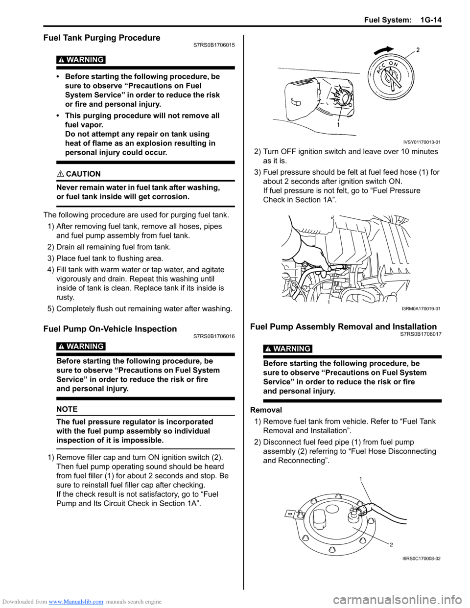
1) Remove filler cap and turn ON ignition switch (2).
Then fuel pump operating sound should be heard
from fuel filler (1) for about 2 seconds and stop. Be
sure to reinstall fuel filler cap after checking.
If the check result is not satisfactory, go to “Fuel
Pump and Its Circuit Check in Section 1A”. 2) Turn OFF ignition switch and leave over 10 minutes
as it is.
3) Fuel pressure should be felt at fuel feed hose (1) for about 2 seconds after ignition switch ON.
If fuel pressure is not felt, go to “Fuel Pressure
Check in Section 1A”.
Fuel Pump Assembly Removal and InstallationS7RS0B1706017
WARNING!
Before starting the following procedure, be
sure to observe “Precautions on Fuel System
Service” in order to reduce the risk or fire
and personal injury.
Removal
1) Remove fuel tank from vehicle. Refer to “Fuel Tank Removal and Installation”.
2) Disconnect fuel feed pipe (1) from fuel pump assembly (2) referring to “Fuel Hose Disconnecting
and Reconnecting”.
IVSY01170013-01
1I3RM0A170019-01
1
2
I6RS0C170008-02
Page 460 of 1496
Downloaded from www.Manualslib.com manuals search engine 2C-6 Rear Suspension:
Spring Upper Seat and Lower Seat Removal and
Installation
S7RS0B2306007
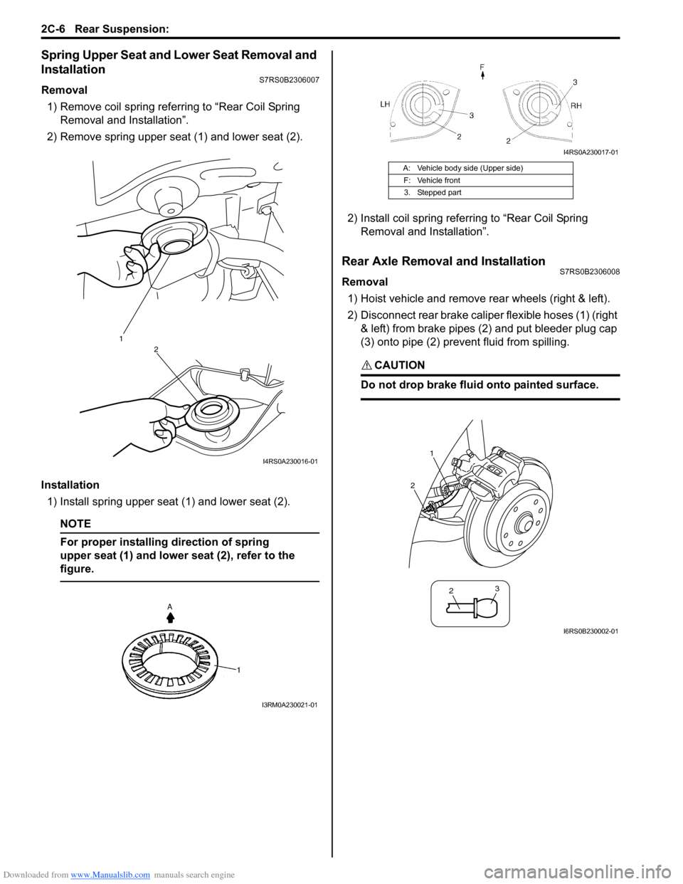
Removal1) Remove coil spring referring to “Rear Coil Spring Removal and Installation”.
2) Remove spring upper seat (1) and lower seat (2).
Installation 1) Install spring upper seat (1) and lower seat (2).
NOTE
For proper installing direction of spring
upper seat (1) and lower seat (2), refer to the
figure.
2) Install coil spring referr ing to “Rear Coil Spring
Removal and Installation”.
Rear Axle Removal and InstallationS7RS0B2306008
Removal
1) Hoist vehicle and remove rear wheels (right & left).
2) Disconnect rear brake caliper flexible hoses (1) (right & left) from brake pipes (2) and put bleeder plug cap
(3) onto pipe (2) prevent fluid from spilling.
CAUTION!
Do not drop brake fluid onto painted surface.
1
2
I4RS0A230016-01
I3RM0A230021-01
A: Vehicle body side (Upper side)
F: Vehicle front3. Stepped part
I4RS0A230017-01
1
2
2 3
I6RS0B230002-01
Page 461 of 1496
Downloaded from www.Manualslib.com manuals search engine Rear Suspension: 2C-7
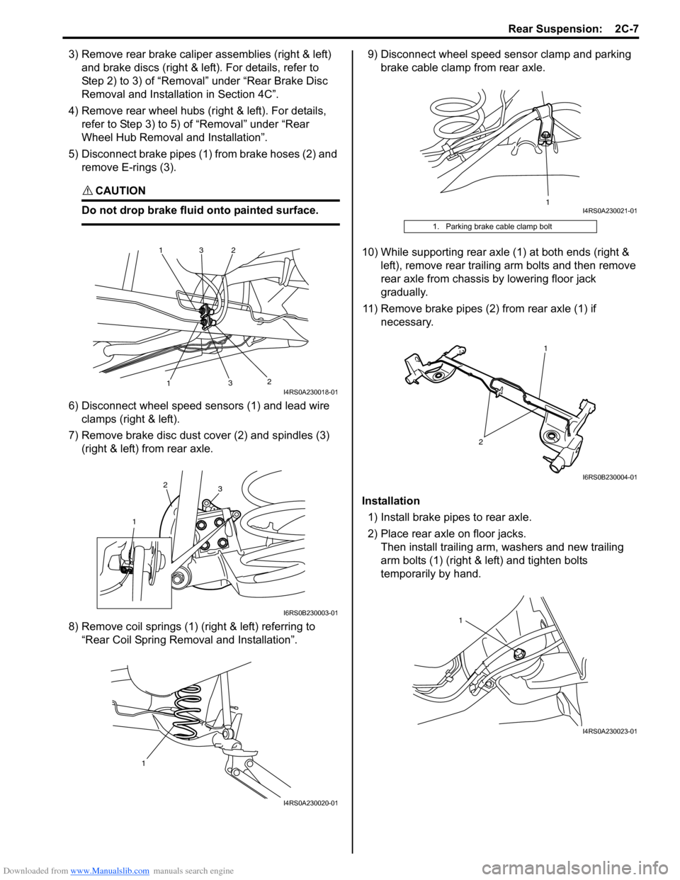
3) Remove rear brake caliper assemblies (right & left)
and brake discs (right & left ). For details, refer to
Step 2) to 3) of “Removal” under “Rear Brake Disc
Removal and Installa tion in Section 4C”.
4) Remove rear wheel hubs (r ight & left). For details,
refer to Step 3) to 5) of “Removal” under “Rear
Wheel Hub Removal and Installation”.
5) Disconnect brake pipes (1) from brake hoses (2) and remove E-rings (3).
CAUTION!
Do not drop brake fluid onto painted surface.
6) Disconnect wheel speed sensors (1) and lead wire clamps (right & left).
7) Remove brake disc dust cover (2) and spindles (3) (right & left) from rear axle.
8) Remove coil springs (1) (right & left) referring to “Rear Coil Spring Removal and Installation”. 9) Disconnect wheel speed sensor clamp and parking
brake cable clamp from rear axle.
10) While supporting rear axle (1) at both ends (right & left), remove rear trailing arm bolts and then remove
rear axle from chassis by lowering floor jack
gradually.
11) Remove brake pipes (2) from rear axle (1) if necessary.
Installation 1) Install brake pipes to rear axle.
2) Place rear axle on floor jacks. Then install trailing arm, washers and new trailing
arm bolts (1) (right & left) and tighten bolts
temporarily by hand.
1
1
2
2
3
3I4RS0A230018-01
1
2
3
I6RS0B230003-01
1
I4RS0A230020-01
1. Parking brake cable clamp bolt
1I4RS0A230021-01
2
1
I6RS0B230004-01
1
I4RS0A230023-01
Page 462 of 1496
Downloaded from www.Manualslib.com manuals search engine 2C-8 Rear Suspension:
3) Install coil springs (right & left) on spring seats of rear
axle referring to “Spring Upper Seat and Lower Seat
Removal and Installation” and “Rear Coil Spring
Removal and Installation”.
4) Install shock absorbers lower side (right & left) and washers referring to “Rear Shock Absorber Removal
and Installation”.
5) Install brake dust covers, spindles and wheel speed sensors (right and left) referring to “Spindle Removal
and Installation”.
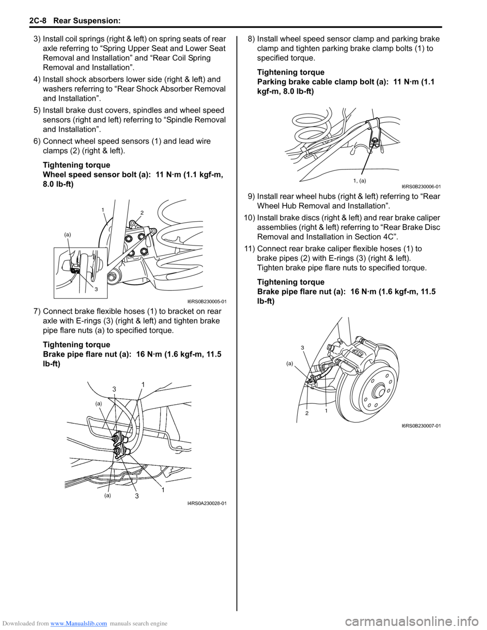
6) Connect wheel speed sensors (1) and lead wire clamps (2) (right & left).
Tightening torque
Wheel speed sensor bolt (a): 11 N·m (1.1 kgf-m,
8.0 lb-ft)
7) Connect brake flexible hoses (1) to bracket on rear axle with E-rings (3) (right & left) and tighten brake
pipe flare nuts (a) to specified torque.
Tightening torque
Brake pipe flare nut (a): 16 N·m (1.6 kgf-m, 11.5
lb-ft) 8) Install wheel speed sensor clamp and parking brake
clamp and tighten parking brake clamp bolts (1) to
specified torque.
Tightening torque
Parking brake cable clamp bolt (a): 11 N·m (1.1
kgf-m, 8.0 lb-ft)
9) Install rear wheel hubs (right & left) referring to “Rear Wheel Hub Removal and Installation”.
10) Install brake discs (right & left) and rear brake caliper assemblies (right & left) referring to “Rear Brake Disc
Removal and Installati on in Section 4C”.
11) Connect rear brake caliper flexible hoses (1) to brake pipes (2) with E-rings (3) (right & left).
Tighten brake pipe flare nuts to specified torque.
Tightening torque
Brake pipe flare nut (a): 16 N·m (1.6 kgf-m, 11.5
lb-ft)
1 2
(a)
3
I6RS0B230005-01
I4RS0A230028-01
1, (a)I6RS0B230006-01
3
2 1
(a)
I6RS0B230007-01
Page 503 of 1496
Downloaded from www.Manualslib.com manuals search engine Brake Control System and Diagnosis: 4A-5
If deterioration of rubber is evident, disassemble all
hydraulic parts and wash with alcohol. Dry these parts
with compressed air before assembly to keep alcohol out
of the system. Replace all rubber parts in the system,
including hoses. Also, when working on the brake
mechanisms, check for fluid on the linings.
If excessive fluid is found, replace the pads. If master cylinder piston seals
are satisfactory, check for
leakage or excessive heat co nditions. If leakage is not
found, drain fluid, flush with brake fluid, refill and bleed
system.
The system must be flushed if there is any doubt as to
the grade of fluid in the system or if fluid has been used
which contained parts that have been subjected to
contaminated fluid.
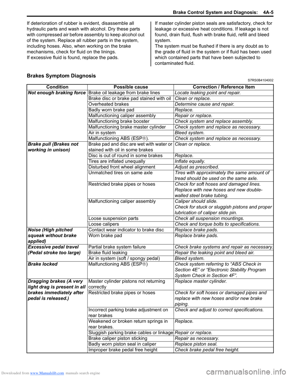
Brakes Symptom DiagnosisS7RS0B4104002
Condition Possible cause Correction / Reference Item
Not enough braking force Brake oil leakage from brake lines Locate leaking point and repair.
Brake disc or brake pad stained with oil Clean or replace.
Overheated brakes Determine cause and repair.
Badly worn brake pad Replace.
Malfunctioning caliper assembly Repair or replace.
Malfunctioning brake booster Check system and replace assembly.
Malfunctioning brake master cylinder Check system and replace as necessary.
Air in system Bleed system.
Malfunctioning ABS (ESP ®). Check system and replace as necessary.
Brake pull (Brakes not
working in unison) Brake pad and disc are wet with water or
stained with oil in some brakes Clean or replace.
Disc is out of round in some brakes Replace.
Tires are inflated unequally Inflate equally.
Disturbed front wheel alignment Adjust as prescribed.
Unmatched tires on same axle Tires with approximately the same amount of
tread should be used on the same axle.
Restricted brake pipes or hoses Check for soft hoses and damaged lines.
Replace with new hoses and new double-
walled steel brake tubing.
Malfunctioning caliper assembly Caliper should slide.
Check for stuck or sluggish pistons and proper
lubrication of caliper slide pin.
Loose suspension parts Check all suspension mountings.
Loose calipers Check and torque bolts to specifications.
Noise (High pitched
squeak without brake
applied) Contact wear indicator to brake disc
Replace brake pads.
Worn brake pad Replace brake pads.
Excessive pedal travel
(Pedal stroke too large) Partial brake system failure
Check brake systems and repair as necessary.
Brake fluid leaking Repair the leaking point and bleed air.
Air in system (soft / spongy pedal) Bleed system.
Brake locked Malfunctioning ABS (ESP®) Check system referri ng to “ABS Check in
Section 4E” or “Electronic Stability Program
System Check in Section 4F”.
Dragging brakes (A very
light drag is present in all
brakes immediately after
pedal is released.) Master cylinder pistons not returning
correctly
Replace master cylinder.
Restricted brake pipes or hoses Check for soft hoses or damaged pipes and
replace with new hoses and/or new brake
piping.
Incorrect parking brake adjustment on
rear brakes Check and adjust to correct specifications.
Weakened or broken return springs in
rear brakes. Replace.
Sluggish parking brake cables or linkage Repair or replace.
Brake caliper piston sticking Repair as necessary.
Badly worn piston seal in caliper Replace piston seal.
Improper brake pedal free height Check brake pedal free height.