waveform no SUZUKI SWIFT 2007 2.G Service Owner's Manual
[x] Cancel search | Manufacturer: SUZUKI, Model Year: 2007, Model line: SWIFT, Model: SUZUKI SWIFT 2007 2.GPages: 1496, PDF Size: 34.44 MB
Page 243 of 1496
Downloaded from www.Manualslib.com manuals search engine Engine General Information and Diagnosis: 1A-193
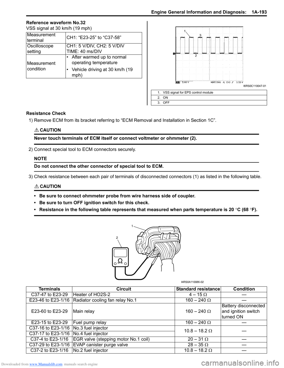
Reference waveform No.32
VSS signal at 30 km/h (19 mph)
Resistance Check1) Remove ECM from its bracket referring to “ECM Removal and Installation in Section 1C”.
CAUTION!
Never touch terminals of ECM itself or connect voltmeter or ohmmeter (2).
2) Connect special tool to ECM connectors securely.
NOTE
Do not connect the other connector of special tool to ECM.
3) Check resistance between each pair of terminals of disconnected connectors (1) as listed in the following table.
CAUTION!
• Be sure to connect ohmmeter probe from wire harness side of coupler.
• Be sure to turn OFF ignition switch for this check.
• Resistance in the following table represents that measured when parts temperature is 20 °C (68 °F).
Measurement
terminal CH1: “E23-25” to “C37-58”
Oscilloscope
setting CH1: 5 V/DIV, CH2: 5 V/DIV
TIME: 40 ms/DIV
Measurement
condition • After warmed up to normal
operating temperature
• Vehicle driving at 30 km/h (19 mph)
1. VSS signal for EPS control module
2. ON
3. OFF
I6RS0C110047-01
1
2
I4RS0A110086-02
Terminals CircuitStandard resistance Condition
C37-47 to E23-29 Heater of HO2S-2 4 – 15 Ω—
E23-46 to E23-1/16 Radiator cooling fan relay No.1 160 – 240 Ω —
E23-60 to E23-29 Main relay 160 – 240 ΩBattery disconnected
and ignition switch
turned ON
E23-15 to E23-29 Fuel pump relay 160 – 240 Ω —
C37-16 to E23-1/16 No.3 fuel injector 10.8 – 18.2 Ω —
C37-17 to E23-1/16 No.4 fuel injector
C37-4 to E23-1/16 EGR valve (st epping motor No.1 coil) 20 – 31 Ω —
C37-29 to E23-1/16 EVAP canister purge valve 28 – 35 Ω —
C37-2 to E23-1/16 No.2 fuel injector 10.8 – 18.2 Ω—
Page 396 of 1496
Downloaded from www.Manualslib.com manuals search engine 1H-4 Ignition System:
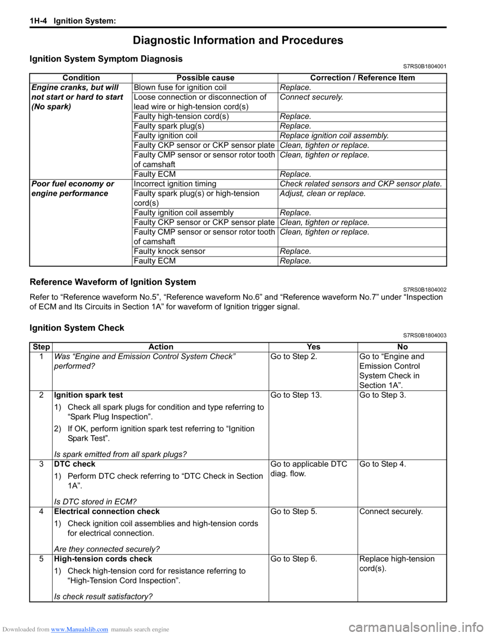
Diagnostic Information and Procedures
Ignition System Symptom DiagnosisS7RS0B1804001
Reference Waveform of Ignition SystemS7RS0B1804002
Refer to “Reference waveform No.5”, “Reference waveform No.6” and “Reference waveform No.7” under “Inspection
of ECM and Its Circuits in Section 1A” for waveform of Ignition trigger signal.
Ignition System CheckS7RS0B1804003
Condition Possible cause Correction / Reference Item
Engine cranks, but will
not start or hard to start
(No spark) Blown fuse for ignition coil
Replace.
Loose connection or disconnection of
lead wire or high-tension cord(s) Connect securely.
Faulty high-tension cord(s) Replace.
Faulty spark plug(s) Replace.
Faulty ignition coil Replace ignition coil assembly.
Faulty CKP sensor or CKP sensor plate Clean, tighten or replace.
Faulty CMP sensor or sensor rotor tooth
of camshaft Clean, tighten or replace.
Faulty ECM Replace.
Poor fuel economy or
engine performance Incorrect ignition timing
Check related sensors and CKP sensor plate.
Faulty spark plug(s) or high-tension
cord(s) Adjust, clean or replace.
Faulty ignition coil assembly Replace.
Faulty CKP sensor or CKP sensor plate Clean, tighten or replace.
Faulty CMP sensor or sensor rotor tooth
of camshaft Clean, tighten or replace.
Faulty knock sensor Replace.
Faulty ECM Replace.
StepAction YesNo
1 Was “Engine and Emission Control System Check”
performed? Go to Step 2.
Go to “Engine and
Emission Control
System Check in
Section 1A”.
2 Ignition spark test
1) Check all spark plugs for condition and type referring to
“Spark Plug Inspection”.
2) If OK, perform ignition spark test referring to “Ignition Spar k Tes t”.
Is spark emitted from all spark plugs? Go to Step 13. Go to Step 3.
3 DTC check
1) Perform DTC check referring to “DTC Check in Section
1A”.
Is DTC stored in ECM? Go to applicable DTC
diag. flow.
Go to Step 4.
4 Electrical connection check
1) Check ignition coil assemblies and high-tension cords
for electrical connection.
Are they connected securely? Go to Step 5.
Connect securely.
5 High-tension cords check
1) Check high-tension cord for resistance referring to
“High-Tension Cord Inspection”.
Is check result satisfactory? Go to Step 6.
Replace high-tension
cord(s).
Page 397 of 1496
Downloaded from www.Manualslib.com manuals search engine Ignition System: 1H-5
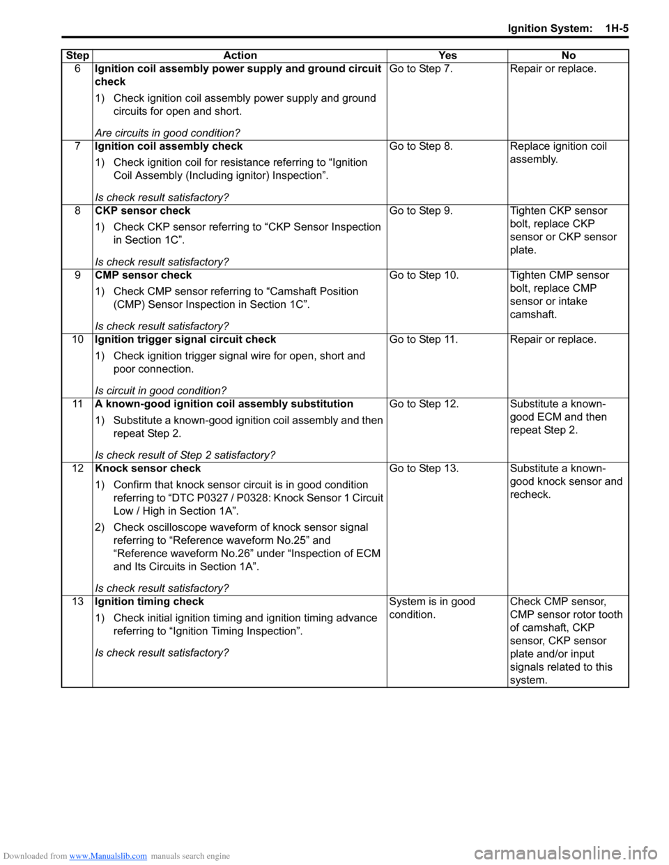
6Ignition coil assembly power supply and ground circuit
check
1) Check ignition coil assembly power supply and ground
circuits for open and short.
Are circuits in good condition? Go to Step 7.
Repair or replace.
7 Ignition coil assembly check
1) Check ignition coil for resistance referring to “Ignition
Coil Assembly (Including ignitor) Inspection”.
Is check result satisfactory? Go to Step 8.
Replace ignition coil
assembly.
8 CKP sensor check
1) Check CKP sensor referring to “CKP Sensor Inspection
in Section 1C”.
Is check result satisfactory? Go to Step 9.
Tighten CKP sensor
bolt, replace CKP
sensor or CKP sensor
plate.
9 CMP sensor check
1) Check CMP sensor referring to “Camshaft Position
(CMP) Sensor Inspection in Section 1C”.
Is check result satisfactory? Go to Step 10. Tighten CMP sensor
bolt, replace CMP
sensor or intake
camshaft.
10 Ignition trigger signal circuit check
1) Check ignition trigger signal wire for open, short and
poor connection.
Is circuit in good condition? Go to Step 11. Repair or replace.
11 A known-good ignition coil assembly substitution
1) Substitute a known-good ignition coil assembly and then
repeat Step 2.
Is check result of Step 2 satisfactory? Go to Step 12. Substitute a known-
good ECM and then
repeat Step 2.
12 Knock sensor check
1) Confirm that knock sensor circuit is in good condition
referring to “DTC P0327 / P0328: Knock Sensor 1 Circuit
Low / High in Section 1A”.
2) Check oscilloscope waveform of knock sensor signal
referring to “Reference waveform No.25” and
“Reference waveform No.26” under “Inspection of ECM
and Its Circuits in Section 1A”.
Is check result satisfactory? Go to Step 13. Substitute a known-
good knock sensor and
recheck.
13 Ignition timing check
1) Check initial ignition timing and ignition timing advance
referring to “Ignition Timing Inspection”.
Is check result satisfactory? System is in good
condition.
Check CMP sensor,
CMP sensor rotor tooth
of camshaft, CKP
sensor, CKP sensor
plate and/or input
signals related to this
system.
Step
Action YesNo
Page 558 of 1496
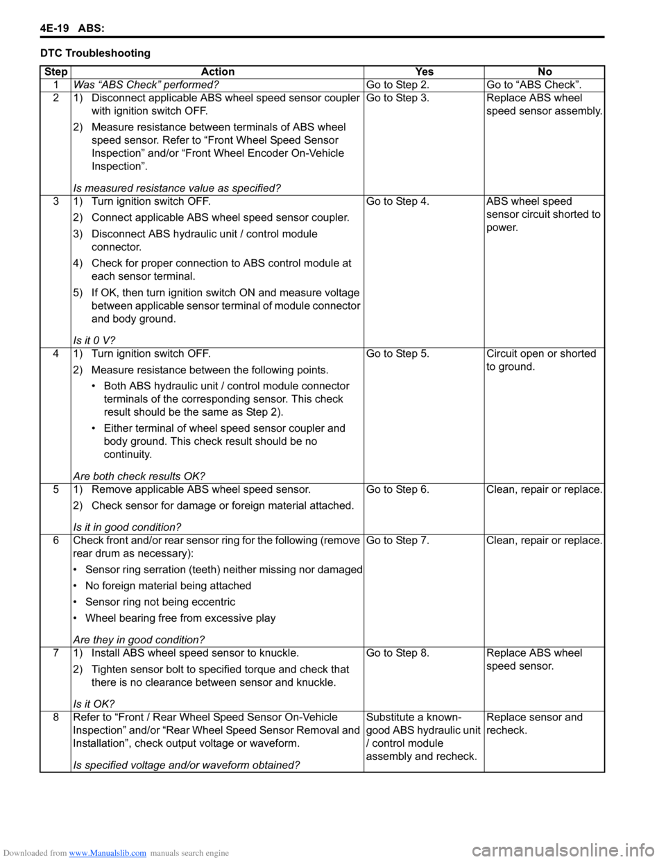
Downloaded from www.Manualslib.com manuals search engine 4E-19 ABS:
DTC TroubleshootingStep Action Yes No 1 Was “ABS Check” performed? Go to Step 2. Go to “ABS Check”.
2 1) Disconnect applicable ABS wheel speed sensor coupler with ignition switch OFF.
2) Measure resistance betw een terminals of ABS wheel
speed sensor. Refer to “Front Wheel Speed Sensor
Inspection” and/or “Front Wheel Encoder On-Vehicle
Inspection”.
Is measured resistance value as specified? Go to Step 3. Replace ABS wheel
speed sensor assembly.
3 1) Turn ignition switch OFF. 2) Connect applicable ABS wh eel speed sensor coupler.
3) Disconnect ABS hydraulic unit / control module connector.
4) Check for proper connection to ABS control module at each sensor terminal.
5) If OK, then turn ignition switch ON and measure voltage between applicable sensor terminal of module connector
and body ground.
Is it 0 V? Go to Step 4. ABS wheel speed
sensor circuit shorted to
power.
4 1) Turn ignition switch OFF. 2) Measure resistance between the following points.• Both ABS hydraulic unit / control module connector terminals of the correspo nding sensor. This check
result should be the same as Step 2).
• Either terminal of wheel speed sensor coupler and body ground. This check result should be no
continuity.
Are both check results OK? Go to Step 5. Circuit open or shorted
to ground.
5 1) Remove applicable ABS wheel speed sensor. 2) Check sensor for damage or foreign material attached.
Is it in good condition? Go to Step 6. Clean, repair or replace.
6 Check front and/or rear sensor ring for the following (remove rear drum as necessary):
• Sensor ring serration (teeth) neither missing nor damaged
• No foreign material being attached
• Sensor ring not being eccentric
• Wheel bearing free from excessive play
Are they in good condition? Go to Step 7. Clean, repair or replace.
7 1) Install ABS wheel speed sensor to knuckle. 2) Tighten sensor bolt to specified torque and check that there is no clearance between sensor and knuckle.
Is it OK? Go to Step 8. Replace ABS wheel
speed sensor.
8 Refer to “Front / Rear Wheel Speed Sensor On-Vehicle Inspection” and/or “Rear Wheel Speed Sensor Removal and
Installation”, check output voltage or waveform.
Is specified voltage and/or waveform obtained? Substitute a known-
good ABS hydraulic unit
/ control module
assembly and recheck.
Replace sensor and
recheck.
Page 570 of 1496
Downloaded from www.Manualslib.com manuals search engine 4E-31 ABS:
2) Bleed air from brake system referring to “Air Bleeding of Brake System in Section 4A”.
3) Check each installed part for fluid leakage and perform “ABS Hydraulic Un it Operation Check”.
NOTE
For new ABS hydraulic unit / control module
assembly, if “ABS Hydraulic Unit Operation
Check” has not been performed, ABS
warning light may flash when ignition switch
is turned ON position.
Accordingly preform “ABS Hydraulic Unit
Operation Check” to stop flashing of ABS
warning light.
Front / Rear Wheel Speed Sensor On-Vehicle
Inspection
S7RS0B4506005
Output Voltage Inspection
1) Disconnect negative cable from battery.
2) Hoist vehicle a little.
3) Disconnect wheel speed sensor connector.
4) Disconnect wheel speed grommet from vehicle body.
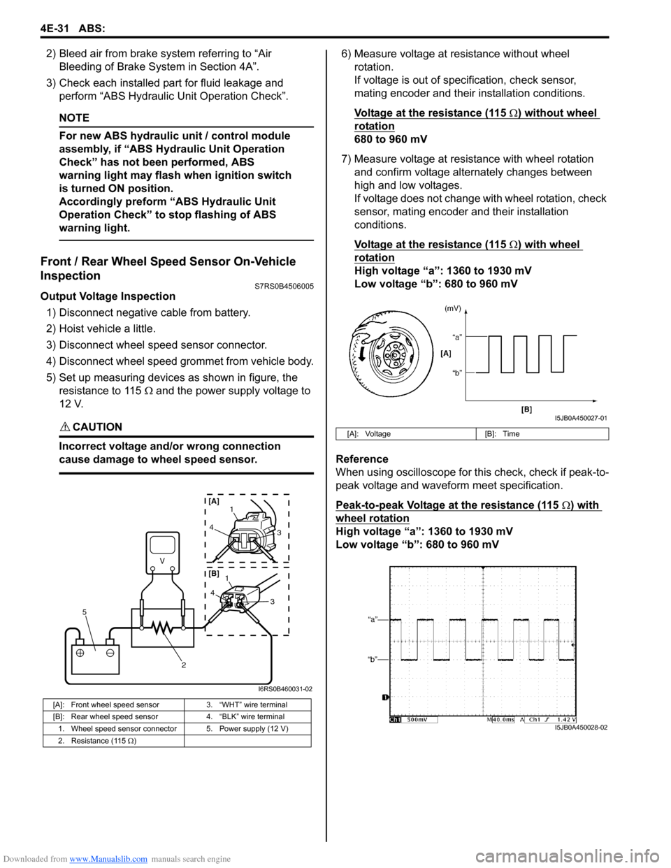
5) Set up measuring devices as shown in figure, the resistance to 115 Ω and the power supply voltage to
12 V.
CAUTION!
Incorrect voltage and/or wrong connection
cause damage to wheel speed sensor.
6) Measure voltage at resistance without wheel rotation.
If voltage is out of specification, check sensor,
mating encoder and their installation conditions.
Voltage at the resistance (115
Ω) without wheel
rotation
680 to 960 mV
7) Measure voltage at resistance with wheel rotation and confirm voltage alternately changes between
high and low voltages.
If voltage does not change with wheel rotation, check
sensor, mating encoder and their installation
conditions.
Voltage at the resistance (115
Ω) with wheel
rotation
High voltage “a”: 1360 to 1930 mV
Low voltage “b”: 680 to 960 mV
Reference
When using oscilloscope for this check, check if peak-to-
peak voltage and waveform meet specification.
Peak-to-peak Voltage at the resistance (115
Ω) with
wheel rotation
High voltage “a”: 1360 to 1930 mV
Low voltage “b”: 680 to 960 mV
[A]: Front wheel speed sensor 3. “WHT” wire terminal
[B]: Rear wheel speed sensor 4. “BLK” wire terminal
1. Wheel speed sensor connector 5. Power supply (12 V)
2. Resistance (115 Ω )
V
2
5
41
3
43
1
[A]
[B]
I6RS0B460031-02
[A]: Voltage [B]: Time
I5JB0A450027-01
I5JB0A450028-02
Page 608 of 1496
Downloaded from www.Manualslib.com manuals search engine 4F-34 Electronic Stability Program:
DTC C1024: Steering Angle Sensor Circuit FailureS7RS0B4604029
DTC Detecting Condition and Trouble Area
DTC Troubleshooting
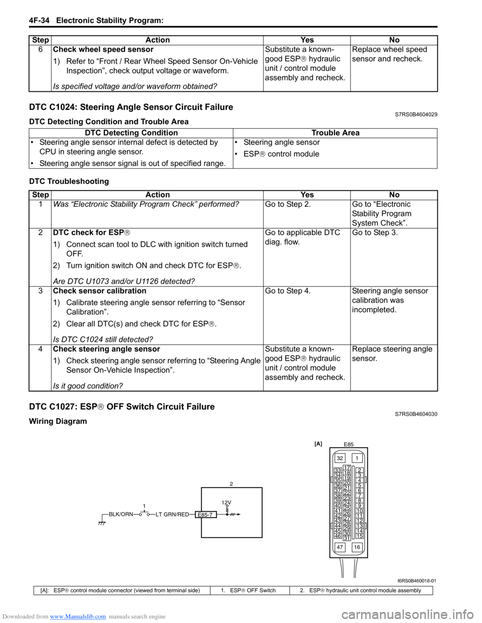
DTC C1027: ESP® OFF Switch Circuit FailureS7RS0B4604030
Wiring Diagram 6
Check wheel speed sensor
1) Refer to “Front / Rear Wheel Speed Sensor On-Vehicle
Inspection”, check output voltage or waveform.
Is specified voltage and/or waveform obtained? Substitute a known-
good ESP
® hydraulic
unit / control module
assembly and recheck. Replace wheel speed
sensor and recheck.
Step
Action YesNo
DTC Detecting Condition Trouble Area
• Steering angle sensor internal defect is detected by CPU in steering angle sensor.
• Steering angle sensor signal is out of specified range. • Steering angle sensor
• ESP
® control module
Step Action YesNo
1 Was “Electronic Stability Pr ogram Check” performed? Go to Step 2.Go to “Electronic
Stability Program
System Check”.
2 DTC check for ESP®
1) Connect scan tool to DLC with ignition switch turned
OFF.
2) Turn ignition switch ON and check DTC for ESP ®.
Are DTC U1073 and/or U1126 detected? Go to applicable DTC
diag. flow.
Go to Step 3.
3 Check sensor calibration
1) Calibrate steering angle sensor referring to “Sensor
Calibration”.
2) Clear all DTC(s) and check DTC for ESP ®.
Is DTC C1024 still detected? Go to Step 4.
Steering angle sensor
calibration was
incompleted.
4 Check steering angle sensor
1) Check steering angle sensor referring to “Steering Angle
Sensor On-Vehicle Inspection”.
Is it good condition? Substitute a known-
good ESP
® hydraulic
unit / control module
assembly and recheck. Replace steering angle
sensor.
[A]
E85
161
15
2
3
4
5
6
7
8
9
10
11
12
13
14
17
18
19
20
21
22
23
24
25
26
27
28
29
30
31
3233
34
35
36
37
38
39
40
41
42
43
44
45
46
47
LT GRN/REDBLK/ORN
12V
E85-7
1 2
I6RS0B460018-01
[A]: ESP
® control module connector (viewed from terminal side) 1. ESP ® OFF Switch 2. ESP ® hydraulic unit control module assembly
Page 632 of 1496
Downloaded from www.Manualslib.com manuals search engine 4F-58 Electronic Stability Program:
6) Measure voltage at resistance without wheel rotation.
If voltage is out of specification, check sensor,
mating encoder and their installation conditions.
Voltage at the resistance (115
Ω) without wheel
rotation
680 to 960 mV
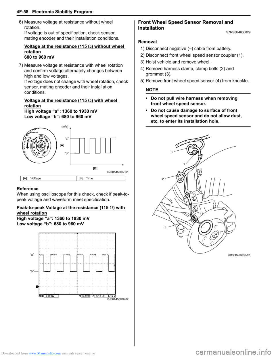
7) Measure voltage at resistance with wheel rotation and confirm voltage alternately changes between
high and low voltages.
If voltage does not change with wheel rotation, check
sensor, mating encoder and their installation
conditions.
Voltage at the resistance (115
Ω) with wheel
rotation
High voltage “a”: 1360 to 1930 mV
Low voltage “b”: 680 to 960 mV
Reference
When using oscilloscope for this check, check if peak-to-
peak voltage and waveform meet specification.
Peak-to-peak Voltage at the resistance (115
Ω) with
wheel rotation
High voltage “a”: 1360 to 1930 mV
Low voltage “b”: 680 to 960 mV
Front Wheel Speed Sensor Removal and
Installation
S7RS0B4606029
Removal
1) Disconnect negative (–) cable from battery.
2) Disconnect front wheel speed sensor coupler (1).
3) Hoist vehicle and remove wheel.
4) Remove harness clamp, clamp bolts (2) and grommet (3).
5) Remove front wheel speed sensor (4) from knuckle.
NOTE
• Do not pull wire harness when removing front wheel speed sensor.
• Do not cause damage to surface of front wheel speed sensor and do not allow dust,
etc. to enter its installation hole.
[A]: Voltage [B]: Time
I5JB0A450027-01
I5JB0A450028-02
3
2
4 1
I6RS0B460032-02
Page 727 of 1496
Downloaded from www.Manualslib.com manuals search engine Automatic Transmission/Transaxle: 5A-83
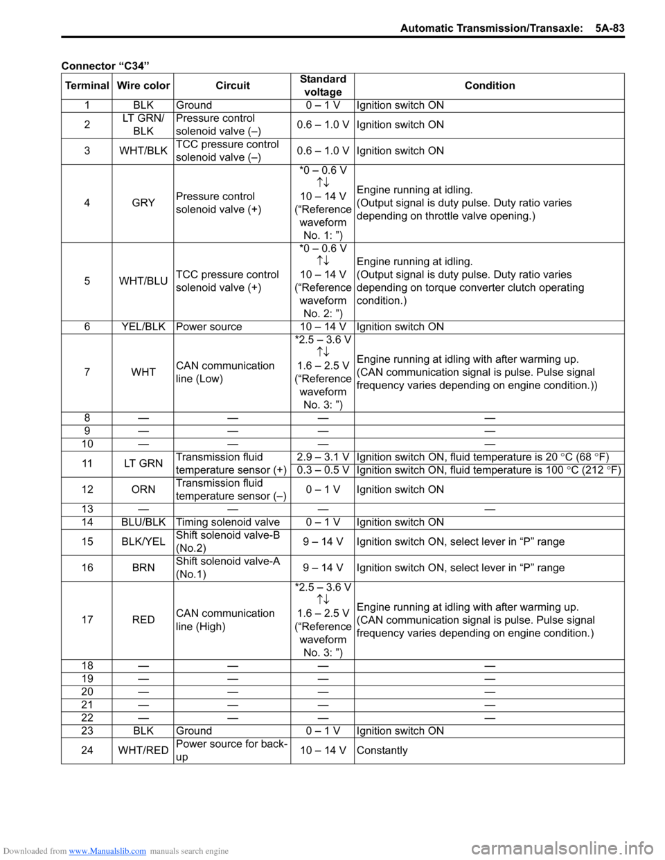
Connector “C34”Terminal Wire color Circuit Standard
voltage Condition
1 BLK Ground 0 – 1 V Ignition switch ON
2 LT GRN/
BLK Pressure control
solenoid valve (–)
0.6 – 1.0 V Ignition switch ON
3WHT/BLK TCC pressure control
solenoid valve (–) 0.6 – 1.0 V Ignition switch ON
4GRY Pressure control
solenoid valve (+) *0 – 0.6 V
↑↓
10 – 14 V
(“Reference waveform No. 1: ”) Engine running at idling.
(Output signal is duty pulse. Duty ratio varies
depending on throttle valve opening.)
5WHT/BLU TCC pressure control
solenoid valve (+) *0 – 0.6 V
↑↓
10 – 14 V
(“Reference waveform No. 2: ”) Engine running at idling.
(Output signal is duty pulse. Duty ratio varies
depending on torque converter clutch operating
condition.)
6 YEL/BLK Power source 10 – 14 V Ignition switch ON
7WHT CAN communication
line (Low) *2.5 – 3.6 V
↑↓
1.6 – 2.5 V
(“Reference waveform No. 3: ”) Engine running at idling with after warming up.
(CAN communication signal is pulse. Pulse signal
frequency varies depending on engine condition.))
8— — — —
9— — — —
10 — —— —
11 LT G R N Transmission fluid
temperature sensor (+) 2.9 – 3.1 V Ignition switch ON, fluid temperature is 20
°C (68 °F)
0.3 – 0.5 V Ignition switch ON, fluid temperature is 100 °C (212 °F)
12 ORN Transmission fluid
temperature sensor (–) 0 – 1 V Ignition switch ON
13 — —— —
14 BLU/BLK Timing solenoid valv e 0 – 1 V Ignition switch ON
15 BLK/YEL Shift solenoid valve-B
(No.2) 9 – 14 V Ignition switch ON, select lever in “P” range
16 BRN Shift solenoid valve-A
(No.1) 9 – 14 V Ignition switch ON, select lever in “P” range
17 RED CAN communication
line (High) *2.5 – 3.6 V
↑↓
1.6 – 2.5 V
(“Reference waveform No. 3: ”) Engine running at idling with after warming up.
(CAN communication signal is pulse. Pulse signal
frequency varies depending on engine condition.)
18 — —— —
19 — —— —
20 — —— —
21 — —— —
22 — —— —
23 BLK Ground 0 – 1 V Ignition switch ON
24 WHT/RED Power source
for back-
up 10 – 14 V Constantly
Page 728 of 1496
Downloaded from www.Manualslib.com manuals search engine 5A-84 Automatic Transmission/Transaxle:
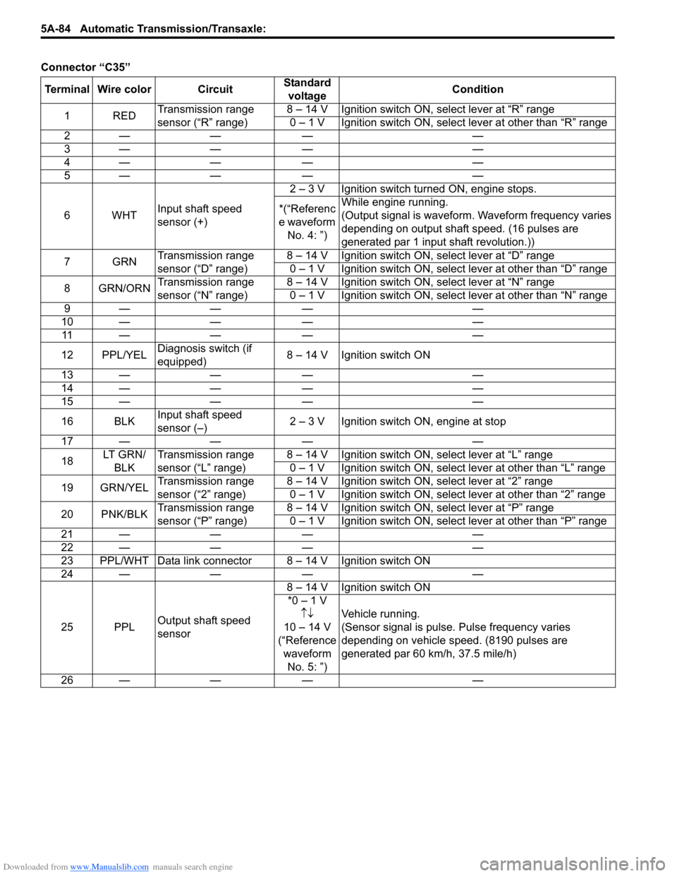
Connector “C35”
Terminal Wire color Circuit Standard
voltage Condition
1RED Transmission range
sensor (“R” range) 8 – 14 V Ignition switch ON, select lever at “R” range
0 – 1 V Ignition switch ON, select lever at other than “R” range
2— — — —
3— — — —
4— — — —
5— — — —
6WHT Input shaft speed
sensor (+) 2 – 3 V Ignition switch turned ON, engine stops.
*(“Referenc
e waveform No. 4: ”) While engine running.
(Output signal is waveform. Waveform frequency varies
depending on output shaft speed. (16 pulses are
generated par 1 input shaft revolution.))
7GRN Transmission range
sensor (“D” range) 8 – 14 V Ignition switch ON, select lever at “D” range
0 – 1 V Ignition switch ON, select lever at other than “D” range
8 GRN/ORN Transmission range
sensor (“N” range) 8 – 14 V Ignition switch ON, select lever at “N” range
0 – 1 V Ignition switch ON, select lever at other than “N” range
9— — — —
10 — — — — 11 — — — —
12 PPL/YEL Diagnosis switch (if
equipped) 8 – 14 V Ignition switch ON
13 — — — —
14 — — — —
15 — — — —
16 BLK Input shaft speed
sensor (–) 2 – 3 V Ignition switch ON, engine at stop
17 — — — —
18 LT G R N /
BLK Transmission range
sensor (“L” range) 8 – 14 V Ignition switch ON, select lever at “L” range
0 – 1 V Ignition switch ON, select lever at other than “L” range
19 GRN/YEL Transmission range
sensor (“2” range) 8 – 14 V Ignition switch ON, select lever at “2” range
0 – 1 V Ignition switch ON, select lever at other than “2” range
20 PNK/BLK Transmission range
sensor (“P” range) 8 – 14 V Ignition switch ON, select lever at “P” range
0 – 1 V Ignition switch ON, select lever at other than “P” range
21 — — — —
22 — — — —
23 PPL/WHT Data link connector 8 – 14 V Ignition switch ON
24 — — — —
25 PPL Output shaft speed
sensor 8 – 14 V Ignition switch ON
*0 – 1 V ↑↓
10 – 14 V
(“Reference waveform No. 5: ”) Vehicle running.
(Sensor signal is pulse. Pulse frequency varies
depending on vehicle speed. (8190 pulses are
generated par 60 km/h, 37.5 mile/h)
26 — — — —
Page 729 of 1496
Downloaded from www.Manualslib.com manuals search engine Automatic Transmission/Transaxle: 5A-85
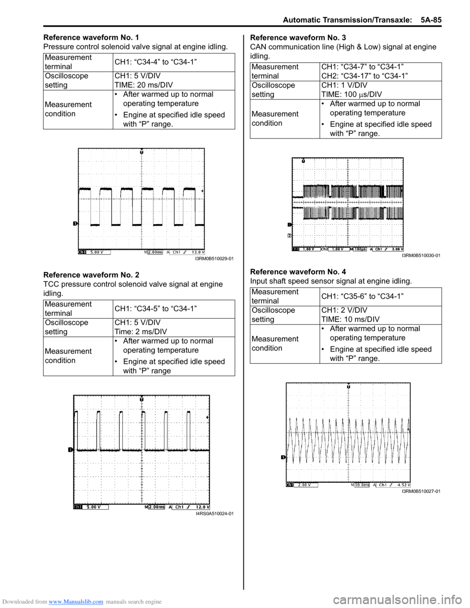
Reference waveform No. 1
Pressure control solenoid valve signal at engine idling.
Reference waveform No. 2
TCC pressure control solenoid valve signal at engine
idling.Reference waveform No. 3
CAN communication line (High & Low) signal at engine
idling.
Reference waveform No. 4
Input shaft speed sensor signal at engine idling.
Measurement
terminal
CH1: “C34-4” to “C34-1”
Oscilloscope
setting CH1: 5 V/DIV
TIME: 20 ms/DIV
Measurement
condition • After warmed up to normal
operating temperature
• Engine at specified idle speed with “P” range.
Measurement
terminal CH1: “C34-5” to “C34-1”
Oscilloscope
setting CH1: 5 V/DIV
Time: 2 ms/DIV
Measurement
condition • After warmed up to normal
operating temperature
• Engine at specified idle speed with “P” range
I3RM0B510029-01
I4RS0A510024-01
Measurement
terminal CH1: “C34-7” to “C34-1”
CH2: “C34-17” to “C34-1”
Oscilloscope
setting CH1: 1 V/DIV
TIME: 100
µs/DIV
Measurement
condition • After warmed up to normal
operating temperature
• Engine at specified idle speed with “P” range.
Measurement
terminal CH1: “C35-6” to “C34-1”
Oscilloscope
setting CH1: 2 V/DIV
TIME: 10 ms/DIV
Measurement
condition • After warmed up to normal
operating temperature
• Engine at specified idle speed with “P” range.
I3RM0B510030-01
I3RM0B510027-01