Steering panel SUZUKI SWIFT 2007 2.G Service Owner's Guide
[x] Cancel search | Manufacturer: SUZUKI, Model Year: 2007, Model line: SWIFT, Model: SUZUKI SWIFT 2007 2.GPages: 1496, PDF Size: 34.44 MB
Page 1360 of 1496

Downloaded from www.Manualslib.com manuals search engine 9F-14 Security and Locks:
Keyless Entry Answer Back Function Change-
over Procedure (If Equipped)
S7RS0B9606016
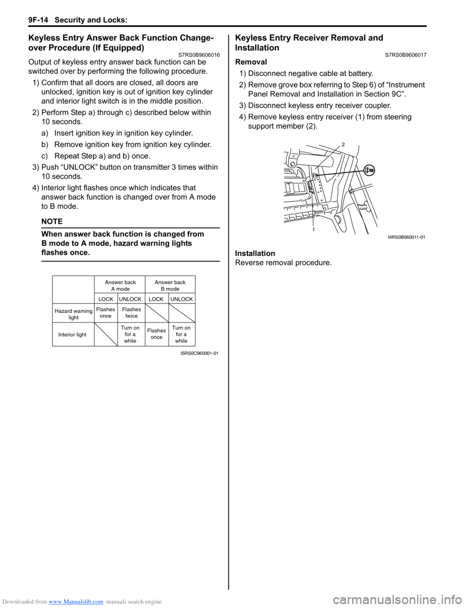
Output of keyless entry answer back function can be
switched over by performing the following procedure.
1) Confirm that all doors are closed, all doors are unlocked, ignition key is out of ignition key cylinder
and interior light switch is in the middle position.
2) Perform Step a) through c) described below within 10 seconds.
a) Insert ignition key in ignition key cylinder.
b) Remove ignition key from ignition key cylinder.
c) Repeat Step a) and b) once.
3) Push “UNLOCK” button on transmitter 3 times within 10 seconds.
4) Interior light flashes once which indicates that answer back function is changed over from A mode
to B mode.
NOTE
When answer back function is changed from
B mode to A mode, hazard warning lights
flashes once.
Keyless Entry Receiver Removal and
Installation
S7RS0B9606017
Removal
1) Disconnect negative cable at battery.
2) Remove grove box referring to Step 6) of “Instrument Panel Removal and Installation in Section 9C”.
3) Disconnect keyless entry receiver coupler.
4) Remove keyless entry receiver (1) from steering support member (2).
Installation
Reverse removal procedure.
Hazard warning light
LOCK LOCK
UNLOCK UNLOCK
Interior lightFlashes
once Flashes
twice
Flashesonce
Turn on
for a
while Turn on
for a
while
Answer back
A mode Answer back
B mode
I5RS0C960001-01
1 2I4RS0B960011-01
Page 1427 of 1496

Downloaded from www.Manualslib.com manuals search engine Body Electrical Control System: 10B-24
DTC U1073 (No. 1073): Control Module Communication Bus OffS7RS0BA204014
Wiring Diagram
Refer to “DTC U0155 (No. 0155): Lost Communication with Instrument Panel Cluster (IPC) Control Module”.
DTC Detecting Condition and Trouble Area
DTC Confirmation Procedure 1) Connect scan tool to DLC with ignition switch turned OFF.
2) Turn ON ignition switch and clear DTC by using scan tool.
3) Start engine and run it for 1 min. or more.
4) Check DTC.
DTC Troubleshooting DTC detecting condition Trouble area
Transmission error that is inconsistent between transmission data and
transmission monitor (CAN bus monitor) data is detected more than 7
times continuously.
(1 driving detection logic) • CAN communication circuit
• Combination meter
• BCM (included in junction block
assembly)
• TCM (A/T model)
• ABS/ESP ® control module
• Keyless start control module (if equipped)
•ECM
• Steering angle sensor (if equipped)
Step Action YesNo
1 Control module connector check
1) Check connection of connectors of all control modules
communicating by means of CAN.
2) Recheck DTC.
Is DTC U1073 detected? Go to Step 2.
Intermittent trouble.
Check for intermittent
referring to “Intermittent
and Poor Connection
Inspection in Section
00”.
2 CAN communication circuit check
1) Turn ignition switch to OFF position.
2) Disconnect connectors of all control modules
communicating by means of CAN.
3) Check CAN communication circuit between control modules for open, short and high resistance.
Is each CAN communication circuit in good condition? Go to Step 3.
Repair circuit.
Page 1493 of 1496

Downloaded from www.Manualslib.com manuals search engine Keyless Start System: 10E-31
Front Door (Driver and Passenger Side), Rear
End Door Request Switch Inspection
S7RS0BA506002
1) Remove door trim from door panel.For front door trim, refer to Step 1) to 3) of “Front
Door Glass Removal and Inst allation in Section 9E”.
For rear end door trim, refer to Step 1) of “Rear End
Door Lock Assembly Remo val and Installation in
Section 9F”.
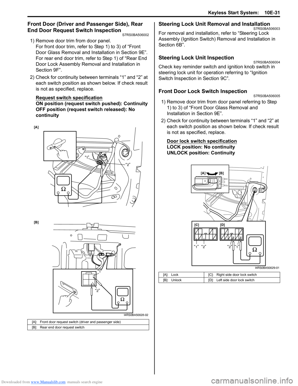
2) Check for continuity between terminals “1” and “2” at each switch position as shown below. If check result
is not as specified, replace.
Request switch specification
ON position (request switch pushed): Continuity
OFF position (request switch released): No
continuity
Steering Lock Unit Removal and InstallationS7RS0BA506003
For removal and installation, refer to “Steering Lock
Assembly (Ignition Switch) Removal and Installation in
Section 6B”.
Steering Lock Unit InspectionS7RS0BA506004
Check key reminder switch and ignition knob switch in
steering lock unit for operation referring to “Ignition
Switch Inspection in Section 9C”.
Front Door Lock Switch InspectionS7RS0BA506005
1) Remove door trim from door panel referring to Step 1) to 3) of “Front Door Glass Removal and
Installation in Section 9E”.
2) Check for continuity between terminals “1” and “2” at each switch position as sh own below. If check result
is not as specified, replace.
Door lock switch specification
LOCK position: No continuity
UNLOCK position: Continuity
[A]: Front door request switch (driver and passenger side)
[B]: Rear end door request switch
[A]
1
2
[B]
1
2
I4RS0BA50028-02
[A]: Lock [C]: Right side door lock switch
[B]: Unlock [D]: Left side door lock switch
[C][D]
[A] [B]
1212
I4RS0BA50029-01
Page 1494 of 1496

Downloaded from www.Manualslib.com manuals search engine 10E-32 Keyless Start System:
Keyless Start Control Module Removal and
Installation
S7RS0BA506006
Removal1) Disconnect negative (–) cable at battery.
2) Remove glove box from instrument panel.
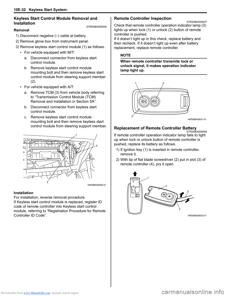
3) Remove keyless start cont rol module (1) as follows.
• For vehicle equipped with M/T:
a. Disconnect connector from keyless start control module.
b. Remove keyless start control module mounting bolt and then remove keyless start
control module from steering support member
(2).
• For vehicle equipped with A/T: a. Remove TCM (3) from vehicle body referring to “Transmission Control Module (TCM)
Removal and Installation in Section 5A”.
b. Disconnect connector from keyless start control module.
c. Remove keyless start control module mounting bolt and then remove keyless start
control module from steering support member.
Installation
For installation, reverse removal procedure.
If Keyless start control module is replaced, register ID
code of remote controller in to Keyless start control
module, referring to “Registration Procedure for Remote
Controller ID Code”.
Remote Controller InspectionS7RS0BA506007
Check that remote controller operation indicator lamp (3)
lights up when lock (1) or un lock (2) button of remote
controller is pushed.
If it doesn’t light up in this check, replace battery and
then recheck. If it doesn’t light up even after battery
replacement, replace remote controller.
NOTE
When remote controller transmits lock or
unlock signal, it makes operation indicator
lamp light up.
Replacement of Remote Controller BatteryS7RS0BA506008
If remote controller operation i ndicator lamp fails to light
up when lock or unlock button of remote controller is
pushed, replace its battery as follows.
1) If ignition key (1) is inse rted in remote controller,
remove it.
2) With tip of flat blade screwdriver (2) put in slot (3) of remote controller (4), pry it open.1
3
2
I4RS0BA50030-01
12
3I4RS0BA50031-01
1
4
2
3
I4RS0BA50032-01