low SUZUKI SWIFT 2007 2.G Service Workshop Manual
[x] Cancel search | Manufacturer: SUZUKI, Model Year: 2007, Model line: SWIFT, Model: SUZUKI SWIFT 2007 2.GPages: 1496, PDF Size: 34.44 MB
Page 659 of 1496
Downloaded from www.Manualslib.com manuals search engine Automatic Transmission/Transaxle: 5A-15
Diagnostic Information and Procedures
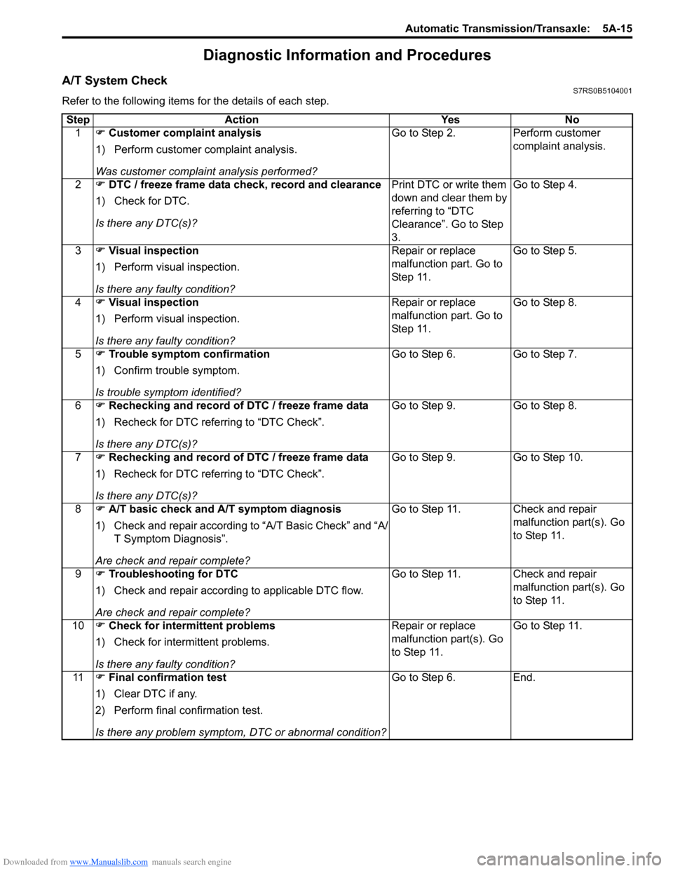
A/T System CheckS7RS0B5104001
Refer to the following items for the details of each step.Step Action Yes No 1 ) Customer complaint analysis
1) Perform customer complaint analysis.
Was customer complaint analysis performed? Go to Step 2. Perform customer
complaint analysis.
2 ) DTC / freeze frame data check, record and clearance
1) Check for DTC.
Is there any DTC(s)? Print DTC or write them
down and clear them by
referring to “DTC
Clearance”. Go to Step
3.Go to Step 4.
3 ) Visual inspection
1) Perform visual inspection.
Is there any faulty condition? Repair or replace
malfunction part. Go to
St ep 11 .
Go to Step 5.
4 ) Visual inspection
1) Perform visual inspection.
Is there any faulty condition? Repair or replace
malfunction part. Go to
St ep 11 .
Go to Step 8.
5 ) Trouble symptom confirmation
1) Confirm trouble symptom.
Is trouble symptom identified? Go to Step 6.
Go to Step 7.
6 ) Rechecking and record of DTC / freeze frame data
1) Recheck for DTC referring to “DTC Check”.
Is there any DTC(s)? Go to Step 9.
Go to Step 8.
7 ) Rechecking and record of DTC / freeze frame data
1) Recheck for DTC referring to “DTC Check”.
Is there any DTC(s)? Go to Step 9.
Go to Step 10.
8 ) A/T basic check and A/T symptom diagnosis
1) Check and repair according to “A/T Basic Check” and “A/
T Symptom Diagnosis”.
Are check and repair complete? Go to Step 11. Check and repair
malfunction part(s). Go
to Step 11.
9 ) Troubleshooting for DTC
1) Check and repair according to applicable DTC flow.
Are check and repair complete? Go to Step 11. Check and repair
malfunction part(s). Go
to Step 11.
10 ) Check for intermittent problems
1) Check for interm ittent problems.
Is there any faulty condition? Repair or replace
malfunction part(s). Go
to Step 11.
Go to Step 11.
11 ) Final confirmation test
1) Clear DTC if any.
2) Perform final confirmation test.
Is there any problem symptom, DTC or abnormal condition? Go to Step 6.
End.
Page 661 of 1496
Downloaded from www.Manualslib.com manuals search engine Automatic Transmission/Transaxle: 5A-17
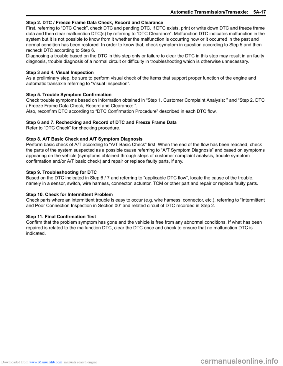
Step 2. DTC / Freeze Frame Data Check, Record and Clearance
First, referring to “DTC Check”, check DTC and pending DTC. If DTC exists, print or write down DTC and freeze frame
data and then clear malfunction DTC(s) by referring to “DTC Clearance”. Malfunction DTC indicates malfunction in the
system but it is not possible to know from it whether the malfunction is occurring now or it occurred in the past and
normal condition has been restored. In order to know that, check symptom in question according to Step 5 and then
recheck DTC according to Step 6.
Diagnosing a trouble based on the DTC in this step only or fa ilure to clear the DTC in this step may result in an faulty
diagnosis, trouble diagnosis of a normal circuit or difficulty in troubleshooting which is otherwise unnecessary.
Step 3 and 4. Visual Inspection
As a preliminary step, be sure to perform visual check of the items that support proper function of the engine and
automatic transaxle referring to “Visual Inspection”.
Step 5. Trouble Symptom Confirmation
Check trouble symptoms based on information obtained in “Step 1. Customer Complaint Analysis: ” and “Step 2. DTC
/ Freeze Frame Data Check, Record and Clearance: ”.
Also, reconfirm DTC according to “DTC Confirmation Procedure” described in each DTC flow.
Step 6 and 7. Rechecking and Record of DTC and Freeze Frame Data
Refer to “DTC Check” for checking procedure.
Step 8. A/T Basic Check and A/T Symptom Diagnosis
Perform basic check of A/T according to “A/T Basic Check” first. When the end of the flow has been reached, check
the parts of the system suspected as a possible cause referring to “A/T Symptom Diagnosis” and based on symptoms
appearing on the vehicle (symptoms obtained through step s of customer complaint analysis, trouble symptom
confirmation and/or A/T basic check) and re pair or replace faulty parts, if any.
Step 9. Troubleshooting for DTC
Based on the DTC indicated in Step 6 / 7 and referring to “a pplicable DTC flow”, locate the cause of the trouble,
namely in a sensor, switch, wire harness, connector, actuator, TCM or other part and repair or replace faulty parts.
Step 10. Check for Intermittent Problem
Check parts where an intermittent trouble is easy to occur (e.g . wire harness, connector, etc.), referring to “Intermittent
and Poor Connection Inspection in Section 00” and related circuit of DTC recorded in Step 2.
Step 11. Final Confirmation Test
Confirm that the problem symptom has gone and the vehicl e is free from any abnormal conditions. If what has been
repaired is related to the malfunction DTC, clear the DTC once and check to ensure that no malfunction DTC is
indicated.
Page 662 of 1496
Downloaded from www.Manualslib.com manuals search engine 5A-18 Automatic Transmission/Transaxle:
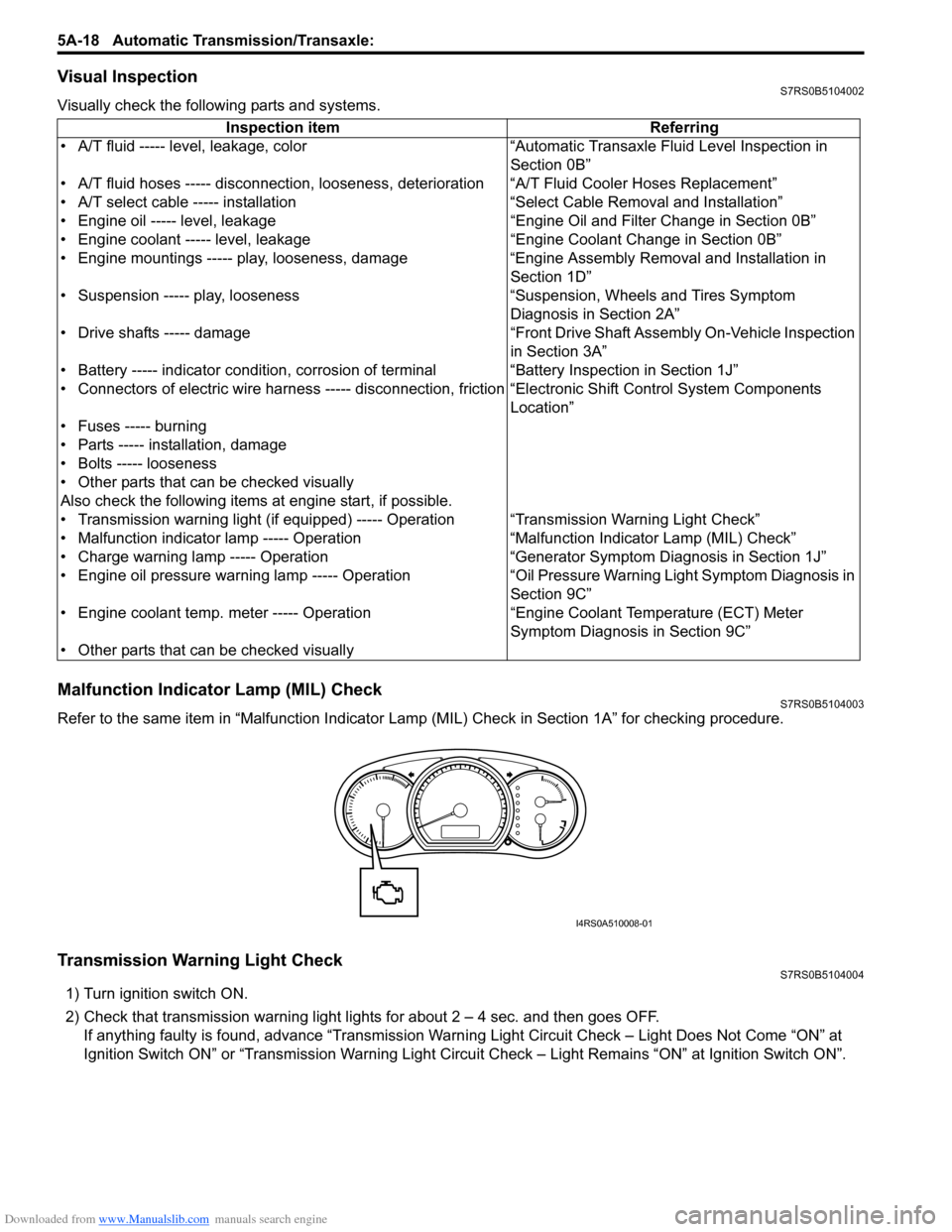
Visual InspectionS7RS0B5104002
Visually check the following parts and systems.
Malfunction Indicator Lamp (MIL) CheckS7RS0B5104003
Refer to the same item in “Malfunction Indicator Lam p (MIL) Check in Section 1A” for checking procedure.
Transmission Warning Light CheckS7RS0B5104004
1) Turn ignition switch ON.
2) Check that transmission warning light lights for about 2 – 4 sec. and then goes OFF.
If anything faulty is found, advance “Transmission Warn ing Light Circuit Check – Light Does Not Come “ON” at
Ignition Switch ON” or “Transmission Warning Light Circu it Check – Light Remains “ON” at Ignition Switch ON”.
Inspection item Referring
• A/T fluid ----- level, leakage, color “Automatic Transaxle Fluid Level Inspection in Section 0B”
• A/T fluid hoses ----- disconnection, looseness, deterioration “A/T Fluid Cooler Hoses Replacement”
• A/T select cable ----- installation “S elect Cable Removal and Installation”
• Engine oil ----- level, leakage “Engine Oil and Filter Change in Section 0B”
• Engine coolant ----- level, leakage “Engine Coolant Change in Section 0B”
• Engine mountings ----- play, looseness, damage “Engine Assembly Removal and Installation in Section 1D”
• Suspension ----- play, looseness “Suspension, Wheels and Tires Symptom Diagnosis in Section 2A”
• Drive shafts ----- damage “Front Drive Shaft Assembly On-Vehicle Inspection in Section 3A”
• Battery ----- indicator condition, corrosion of terminal “Battery Inspection in Section 1J”
• Connectors of electric wire harness ----- disconnection, friction “Electronic Shift Control System Components
Location”
• Fuses ----- burning
• Parts ----- installation, damage
• Bolts ----- looseness
• Other parts that can be checked visually
Also check the following items at engine start, if possible.
• Transmission warning light (if equipped) ----- Operation “Transmission Warning Light Check”
• Malfunction indicator lamp ----- Operation “Malfunction Indicator Lamp (MIL) Check”
• Charge warning lamp ----- Operation “Generator Symptom Diagnosis in Section 1J”
• Engine oil pressure warning lamp ----- Operation “Oil Pressure Warning Ligh t Symptom Diagnosis in
Section 9C”
• Engine coolant temp. meter ----- Operation “Engine Coolant Temperature (ECT) Meter
Symptom Diagnosis in Section 9C”
• Other parts that can be checked visually
I4RS0A510008-01
Page 663 of 1496
Downloaded from www.Manualslib.com manuals search engine Automatic Transmission/Transaxle: 5A-19
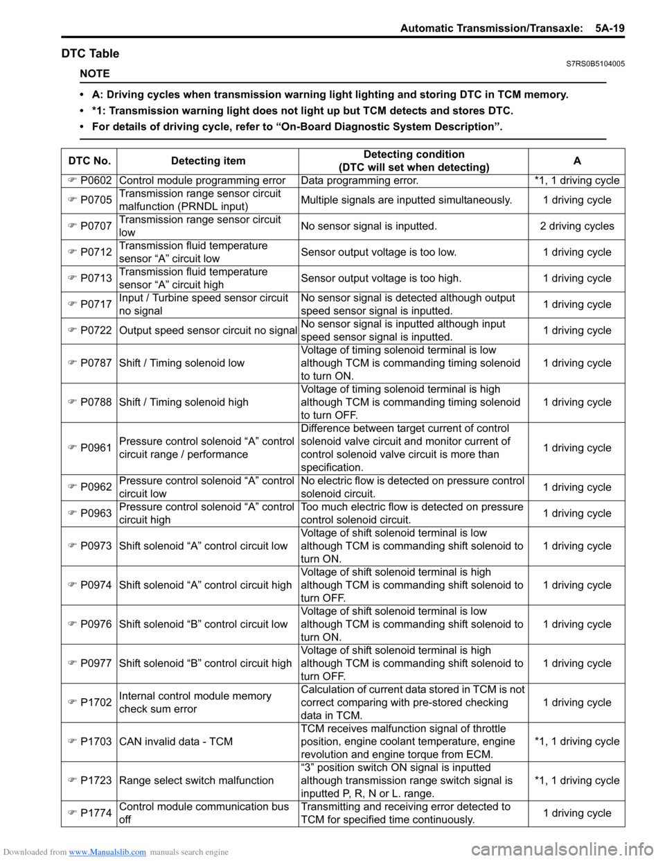
DTC TableS7RS0B5104005
NOTE
• A: Driving cycles when transmission warning light lighting and storing DTC in TCM memory.
• *1: Transmission warning light does not light up but TCM detects and stores DTC.
• For details of driving cycle, refer to “On-Board Diagnostic System Description”.
DTC No.Detecting item Detecting condition
(DTC will set when detecting) A
) P0602 Control module programming error D ata programming error. *1, 1 driving cycle
) P0705 Transmission range sensor circuit
malfunction (PRNDL input) Multiple signals are inputted
simultaneously. 1 driving cycle
) P0707 Transmission range sensor circuit
low No sensor signal is inputted.
2 driving cycles
) P0712 Transmission fluid temperature
sensor “A” circuit low Sensor output voltage is too low.
1 driving cycle
) P0713 Transmission fluid temperature
sensor “A” circuit high Sensor output voltage is too high.
1 driving cycle
) P0717 Input / Turbine speed sensor circuit
no signal No sensor signal is detected although output
speed sensor signal is inputted.
1 driving cycle
) P0722 Output speed sensor circuit no signal No sensor signal is inputted although input
speed sensor signal is inputted. 1 driving cycle
) P0787 Shift / Timing solenoid low Voltage of timing solenoid terminal is low
although TCM is commanding timing solenoid
to turn ON. 1 driving cycle
) P0788 Shift / Timing solenoid high Voltage of timing solenoid terminal is high
although TCM is commanding timing solenoid
to turn OFF. 1 driving cycle
) P0961 Pressure control solenoid “A” control
circuit range / performance Difference between target current of control
solenoid valve circuit and monitor current of
control solenoid valve circuit is more than
specification.
1 driving cycle
) P0962 Pressure control solenoid “A” control
circuit low No electric flow is detected on pressure control
solenoid circuit.
1 driving cycle
) P0963 Pressure control solenoid “A” control
circuit high Too much electric flow is detected on pressure
control solenoid circuit.
1 driving cycle
) P0973 Shift solenoid “A” control circuit low Voltage of shift solenoid terminal is low
although TCM is commanding shift solenoid to
turn ON. 1 driving cycle
) P0974 Shift solenoid “A” control circuit high Voltage of shift solenoid terminal is high
although TCM is commanding shift solenoid to
turn OFF. 1 driving cycle
) P0976 Shift solenoid “B” control circuit low Voltage of shift solenoid terminal is low
although TCM is commanding shift solenoid to
turn ON. 1 driving cycle
) P0977 Shift solenoid “B” control circuit high Voltage of shift solenoid terminal is high
although TCM is commanding shift solenoid to
turn OFF. 1 driving cycle
) P1702 Internal control module memory
check sum error Calculation of current data stored in TCM is not
correct comparing with pre-stored checking
data in TCM.
1 driving cycle
) P1703 CAN invalid data - TCM TCM receives malfunction signal of throttle
position
, engine coolan t temperature, engine
revolution and engine torque from ECM. *1, 1 driving cycle
) P1723 Range select switch malfunction “3” position switch ON signal is inputted
although transmission range switch signal is
inputted P, R, N or L. range. *1, 1 driving cycle
) P1774 Control module communication bus
off Transmitting and receiving error detected to
TCM for specified time continuously.
1 driving cycle
Page 664 of 1496
Downloaded from www.Manualslib.com manuals search engine 5A-20 Automatic Transmission/Transaxle:
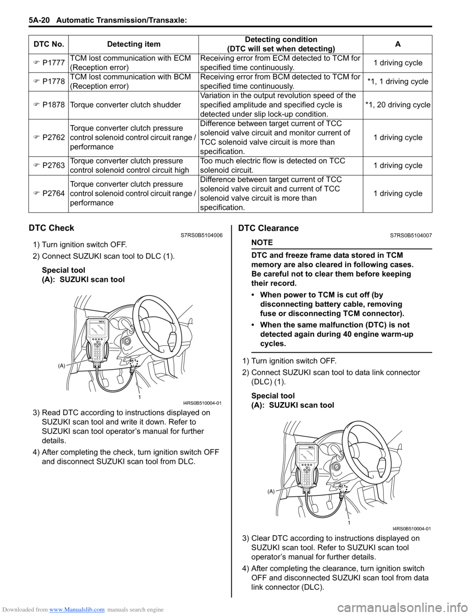
DTC CheckS7RS0B5104006
1) Turn ignition switch OFF.
2) Connect SUZUKI scan tool to DLC (1).
Special tool
(A): SUZUKI scan tool
3) Read DTC according to instructions displayed on SUZUKI scan tool and wr ite it down. Refer to
SUZUKI scan tool operator’s manual for further
details.
4) After completing the check, turn ignition switch OFF
and disconnect SUZUKI scan tool from DLC.
DTC ClearanceS7RS0B5104007
NOTE
DTC and freeze frame data stored in TCM
memory are also cleared in following cases.
Be careful not to clear them before keeping
their record.
• When power to TCM is cut off (by disconnecting battery cable, removing
fuse or disconnecting TCM connector).
• When the same malfunction (DTC) is not detected again during 40 engine warm-up
cycles.
1) Turn ignition switch OFF.
2) Connect SUZUKI scan tool to data link connector (DLC) (1).
Special tool
(A): SUZUKI scan tool
3) Clear DTC according to instructions displayed on SUZUKI scan tool. Refer to SUZUKI scan tool
operator’s manual for further details.
4) After completing the clearance, turn ignition switch OFF and disconnected SUZUKI scan tool from data
link connector (DLC).
)
P1777 TCM lost communication with ECM
(Reception error) Receiving error from ECM detected to TCM for
specified time continuously.
1 driving cycle
) P1778 TCM lost communication with BCM
(Reception error) Receiving error from BCM detected to TCM for
specified time continuously.
*1, 1 driving cycle
) P1878 Torque converter clutch shudder Variation in the output revolution speed of the
specified amplitude and specified cycle is
detected under slip lock-up condition. *1, 20 driving cycle
) P2762 Torque converter clutch pressure
control solenoid control circuit range /
performance Difference between target current of TCC
solenoid valve circuit and monitor current of
TCC solenoid valve ci
rcuit is more than
specification. 1 driving cycle
) P2763 Torque converter clutch pressure
control solenoid control circuit high Too much electric flow is detected on TCC
solenoid circuit.
1 driving cycle
) P2764 Torque converter clutch pressure
control solenoid control circuit range /
performance Difference between target current of TCC
solenoid valve circuit and current of TCC
solenoid valve circuit is more than
specification.
1 driving cycle
DTC No. Detecting item
Detecting condition
(DTC will set when detecting) A
1
(A)I4RS0B510004-01
1
(A)I4RS0B510004-01
Page 665 of 1496
Downloaded from www.Manualslib.com manuals search engine Automatic Transmission/Transaxle: 5A-21
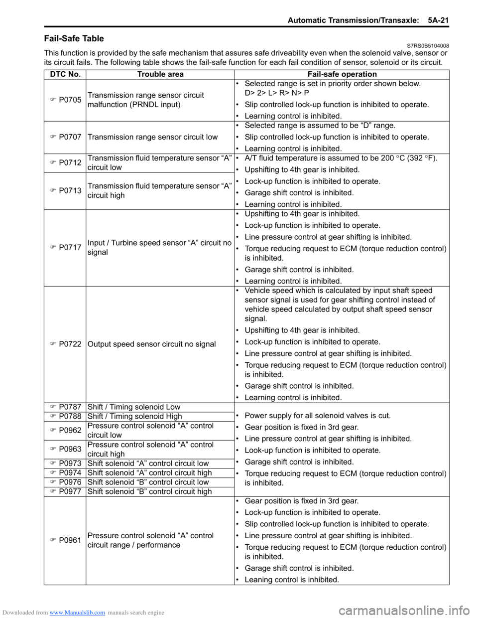
Fail-Safe TableS7RS0B5104008
This function is provided by the safe mechanism that assures safe driveability even when the solenoid valve, sensor or
its circuit fails. The following table shows th e fail-safe function for each fail condition of sensor, solenoid or its circuit.
DTC No. Trouble area Fail-safe operation
) P0705 Transmission range sensor circuit
malfunction (PRNDL input) • Selected range is set in priority order shown below.
D> 2> L> R> N> P
• Slip controlled lock-up function is inhibited to operate.
• Learning control is inhibited.
) P0707 Transmission range sensor circuit low • Selected range is assumed to be “D” range.
• Slip controlled lock-up function is inhibited to operate.
• Learning control is inhibited.
) P0712 Transmission fluid temperature sensor “A”
circuit low • A/T fluid temperature is assumed to be 200
°C (392 °F).
• Upshifting to 4th gear is inhibited.
• Lock-up function is inhibited to operate.
• Garage shift control is inhibited.
• Learning control is inhibited.
)
P0713 Transmission fluid temperature sensor “A”
circuit high
) P0717 Input / Turbine speed sensor “A” circuit no
signal • Upshifting to 4th gear is inhibited.
• Lock-up function is inhibited to operate.
• Line pressure control at gear shifting is inhibited.
• Torque reducing request to ECM (torque reduction control)
is inhibited.
• Garage shift control is inhibited.
• Learning control is inhibited.
) P0722 Output speed sensor circuit no signal • Vehicle speed which is calculated by input shaft speed
sensor signal is used for gear shifting control instead of
vehicle speed calculated by output shaft speed sensor
signal.
• Upshifting to 4th gear is inhibited.
• Lock-up function is inhibited to operate.
• Line pressure control at gear shifting is inhibited.
• Torque reducing request to ECM (torque reduction control) is inhibited.
• Garage shift control is inhibited.
• Learning control is inhibited.
) P0787 Shift / Timing solenoid Low
• Power supply for all solenoid valves is cut.
• Gear position is fixed in 3rd gear.
• Line pressure control at gear shifting is inhibited.
• Look-up function is inhibited to operate.
• Garage shift control is inhibited.
• Torque reducing request to ECM (torque reduction control)
is inhibited.
)
P0788 Shift / Timing solenoid High
) P0962 Pressure control solenoid “A” control
circuit low
) P0963 Pressure control solenoid “A” control
circuit high
) P0973 Shift solenoid “A” control circuit low
) P0974 Shift solenoid “A” control circuit high
) P0976 Shift solenoid “B” control circuit low
) P0977 Shift solenoid “B” control circuit high
) P0961 Pressure control solenoid “A” control
circuit range / performance • Gear position is fixed in 3rd gear.
• Lock-up function is inhibited to operate.
• Slip controlled lock-up function is inhibited to operate.
• Line pressure control at gear shifting is inhibited.
• Torque reducing request to ECM (torque reduction control)
is inhibited.
• Garage shift control is inhibited.
• Leaning control is inhibited.
Page 667 of 1496
Downloaded from www.Manualslib.com manuals search engine Automatic Transmission/Transaxle: 5A-23
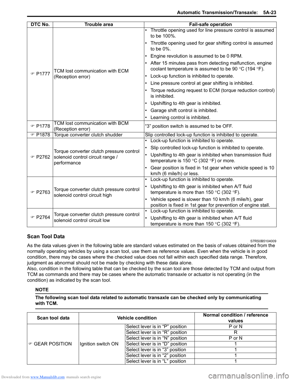
Scan Tool DataS7RS0B5104009
As the data values given in the following table are standard values estimated on the basis of values obtained from the
normally operating vehicles by using a scan tool, use them as reference values. Even when the vehicle is in good
condition, there may be cases where the checked value does not fall within each specified data range. Therefore,
judgment as abnormal should not be made by checking with these data alone.
Also, condition in the following table that can be checked by the scan tool are those detected by TCM and output from
TCM as commands and there may be cases where the auto matic transaxle or actuator is not operating (in the
condition) as indicated by the scan tool.
NOTE
The following scan tool data related to automatic transaxle can be checked only by communicating
with TCM.
) P1777 TCM lost communication with ECM
(Reception error) • Throttle opening used for line pressure control is assumed
to be 100%.
• Throttle opening used for gear shifting control is assumed to be 0%.
• Engine revolution is assumed to be 0 RPM.
• After 15 minutes pass from detecting malfunction, engine coolant temperature is assumed to be 90 °C (194 °F).
• Lock-up function is inhibited to operate.
• Line pressure control at gear shifting is inhibited.
• Torque reducing request to ECM (torque reduction control) is inhibited.
• Upshifting to 4th gear is inhibited.
• Garage shift control is inhibited.
• Learning control is inhibited.
) P1778 TCM lost communication with BCM
(Reception error) “3” position switch is assumed to be OFF.
) P1878 Torque converter clutch shudder Slip contro lled lock-up function is inhibited to operate.
) P2762 Torque converter clutch pressure control
solenoid control circuit range /
performance • Lock-up function is inhibited to operate.
• Slip controlled lock-up function is inhibited to operate.
• Upshifting to 4th gear is inhibited when transmission fluid
temperature is 150 °C (302 ° F) or more.
• Gear position is fixed in 1st gear when vehicle speed is 10 km/h (6 mile/h) or less.
) P2763 Torque converter clutch pressure control
solenoid control circuit high • Lock-up function is inhibited to operate.
• Upshifting to 4th gear is inhibited when A/T fluid
temperature is more than 150 °C (302 °F).
• Vehicle speed is slower than 10 km/h (6 mile/h), gear position is fixed in 1st gear for prevention of engine stall.
) P2764 Torque converter clutch pressure control
solenoid control circuit low • Lock-up function is inhibited to operate.
• Upshifting to 4th gear is inhibited when A/T fluid
temperature is more than 150 °C (302 °F).
DTC No. Trouble area Fail-safe operation
Scan tool data
Vehicle condition Normal condition / reference
values
) GEAR POSITION Ignition switch ON Select lever is in “P” position
P or N
Select lever is in “R” position R
Select lever is in “N” position P or N
Select lever is in “D” position 1
Select lever is in “3” position 1
Select lever is in “2” position 1
Select lever is in “L” position 1
Page 670 of 1496
Downloaded from www.Manualslib.com manuals search engine 5A-26 Automatic Transmission/Transaxle:
TRANSAXLE RANGE
Transaxle range detected by signal fed from
transmission range sensor.
D RANGE SIGNAL
ON: Signal which TCM require ECM to increase idle
speed
OFF: Signal which TCM does not require ECM to
increase idle speed
THROTTLE POSITION (%)
Throttle opening ratio computed by CAN signal from
ECM.
BRAKE SWITCH
Inputted signal from brake light switch on pedal bracket.
ON: Brake pedal depressed
OFF: Brake pedal released
TORQUE REDUCTION SIGNAL
ON: Signal which TCM require ECM to reduce output
torque at shifting gear
OFF: Signal which TCM does not require ECM to reduce
output torque
ENGINE COOLANT TEMPERATURE ( °C, °F)
Engine coolant temperature computed by CAN signal
from ECM. AIR CONDITIONER SIGNAL
ON: Signal which inform that air conditioner compressor
is turned ON.
OFF: Signal which inform that air conditioner
compressor is not turned ON.
ENGINE TORQUE SIGNAL (N
⋅m)
Engine torque computed by duty pulse signal outputted
from ECM.
SLIP RPM (RPM)
This parameter indicates slip ping rotation in the torque
converter (difference between input shaft rotation and
engine rotation)
MIL REQUEST
ON: Signal which TCM requires combination meter to
turn on malfunction indicator lamp.
OFF: Signal which TCM does not require combination
meter to turn on malf unction indicator lamp.
FUEL CUT FLAG
ON: Signal which inform that fuel cut is operating.
OFF: Signal which inform that fuel cut is not operating.
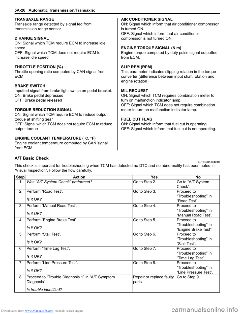
A/T Basic CheckS7RS0B5104010
This check is important for troubleshooting when TCM has detected no DTC and no abnormality has been noted in
“Visual Inspection”. Fo llow the flow carefully.
Step Action YesNo
1 Was “A/T System Check” preformed? Go to Step 2.Go to “A/T System
Check”.
2 Perform “Road Test”.
Is it OK? Go to Step 3.
Proceed to
“Troubleshooting” in
“Road Test”.
3 Perform “Manual Road Test”.
Is it OK? Go to Step 4.
Proceed to
“Troubleshooting” in
“Manual Road Test”.
4 Perform “Engine Brake Test”.
Is it OK? Go to Step 5.
Proceed to
“Troubleshooting” in
“Engine Brake Test”.
5 Perform “Stall Test”.
Is it OK? Go to Step 6.
Proceed to
“Troubleshooting” in
“Stall Test”.
6 Perform “Time Lag Test”.
Is it OK? Go to Step 7.
Proceed to
“Troubleshooting” in
“Time Lag Test”.
7 Perform “Line Pressure Test”.
Is it OK? Go to Step 8.
Proceed to
“Troubleshooting” in
“Line Pressure Test”.
8 Proceed to “Trouble Diag nosis 1” in “A/T Symptom
Diagnosis”.
Is trouble identified? Repair or replace faulty
parts.
Go to Step 9.
Page 674 of 1496
Downloaded from www.Manualslib.com manuals search engine 5A-30 Automatic Transmission/Transaxle:
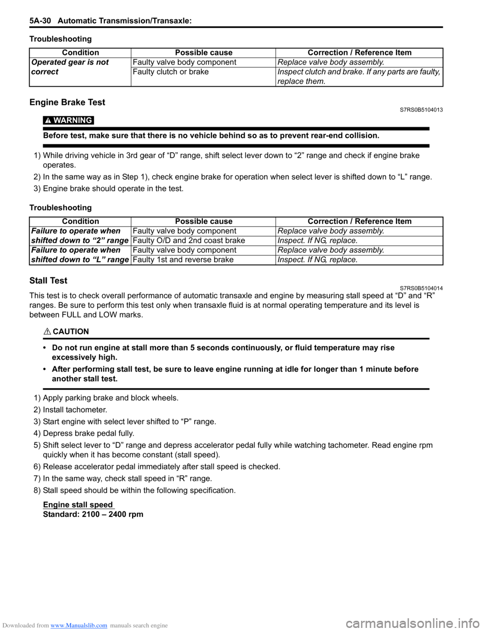
Troubleshooting
Engine Brake TestS7RS0B5104013
WARNING!
Before test, make sure that there is no vehicle behind so as to prevent rear-end collision.
1) While driving vehicle in 3rd gear of “D” range, shift select lever down to “2” range and check if engine brake
operates.
2) In the same way as in Step 1), check engine brake for operation when select lever is shifted down to “L” range.
3) Engine brake should operate in the test.
Troubleshooting
Stall TestS7RS0B5104014
This test is to check overall performance of automatic tr ansaxle and engine by measuring stall speed at “D” and “R”
ranges. Be sure to perform this test only when transaxle fluid is at normal operating temperature and its level is
between FULL and LOW marks.
CAUTION!
• Do not run engine at stall more than 5 seconds continuously, or fluid temperature may rise excessively high.
• After performing stall test, be su re to leave engine running at idle for longer than 1 minute before
another stall test.
1) Apply parking brake and block wheels.
2) Install tachometer.
3) Start engine with select lever shifted to “P” range.
4) Depress brake pedal fully.
5) Shift select lever to “D” range and depress accelerator pedal fully while watching tachometer. Read engine rpm quickly when it has become constant (stall speed).
6) Release accelerator pedal immediately after stall speed is checked.
7) In the same way, check stall speed in “R” range.
8) Stall speed should be withi n the following specification.
Engine stall speed
Standard: 2100 – 2400 rpm Condition Possible cause Correction / Reference Item
Operated gear is not
correct Faulty valve body component
Replace valve body assembly.
Faulty clutch or brake Inspect clutch and brake. If any parts are faulty,
replace them.
Condition Possible cause Correction / Reference Item
Failure to operate when
shifted down to “2” range Faulty valve body component
Replace valve body assembly.
Faulty O/D and 2nd coast brake Inspect. If NG, replace.
Failure to operate when
shifted down to “L” range Faulty valve body component
Replace valve body assembly.
Faulty 1st and reverse brake Inspect. If NG, replace.
Page 675 of 1496
Downloaded from www.Manualslib.com manuals search engine Automatic Transmission/Transaxle: 5A-31
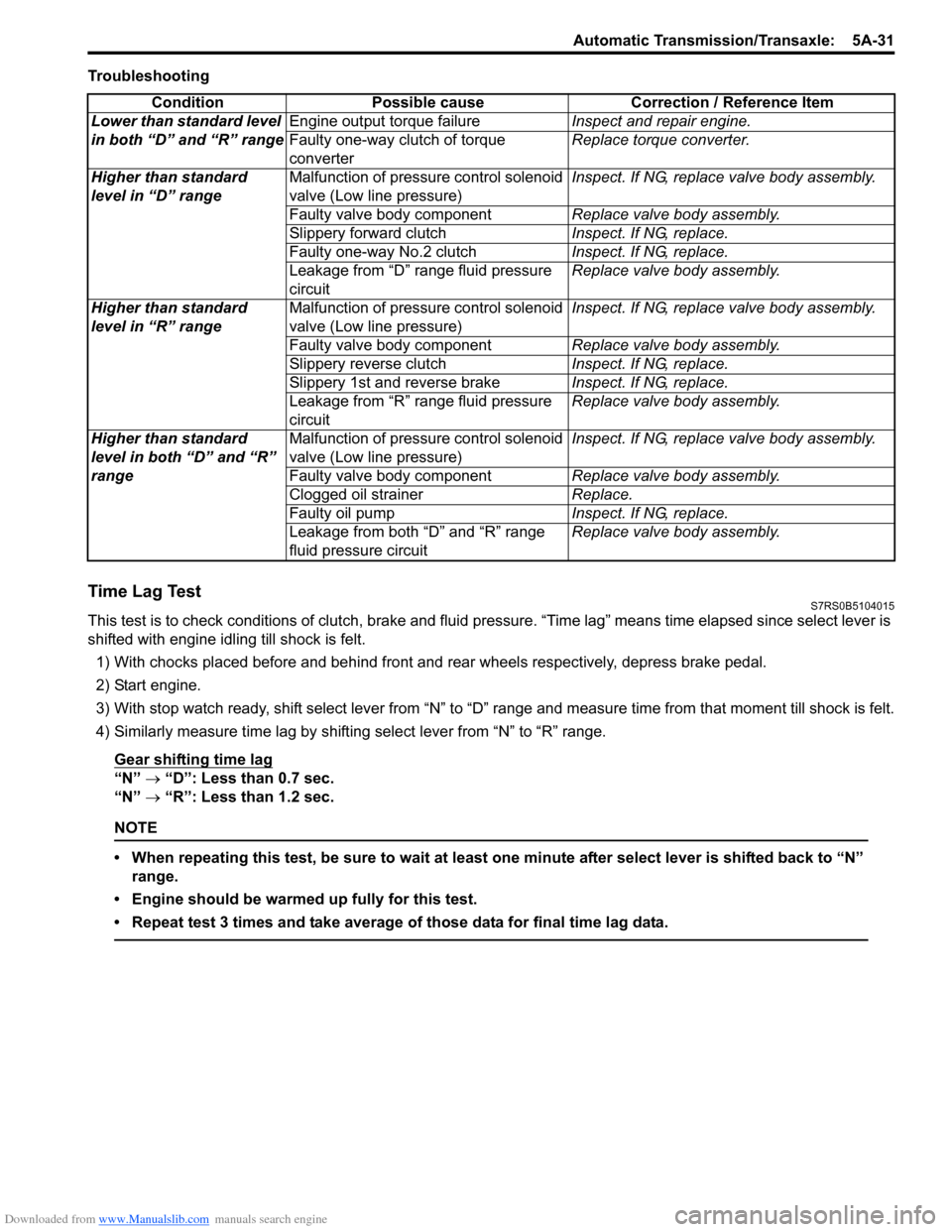
Troubleshooting
Time Lag TestS7RS0B5104015
This test is to check conditions of clutch, brake and fluid pressure. “Time lag” means time elapsed since select lever is
shifted with engine idling till shock is felt.
1) With chocks placed before and behind front and rear wheels respectively, depress brake pedal.
2) Start engine.
3) With stop watch ready, shift select lever from “N” to “D” range an d measure time from that moment till shock is felt.
4) Similarly measure time lag by shifting select lever from “N” to “R” range.
Gear shifting time lag
“N” → “D”: Less than 0.7 sec.
“N” → “R”: Less than 1.2 sec.
NOTE
• When repeating this test, be sure to wait at least one minute after select lever is shifted back to “N”
range.
• Engine should be warmed up fully for this test.
• Repeat test 3 times and take average of those data for final time lag data.
Condition Possible cause Correction / Reference Item
Lower than standard level
in both “D” and “R” range Engine output torque failure
Inspect and repair engine.
Faulty one-way clutch of torque
converter Replace torque converter.
Higher than standard
level in “D” range Malfunction of pressure control solenoid
valve (Low line pressure) Inspect. If NG, replace valve body assembly.
Faulty valve body component Replace valve body assembly.
Slippery forward clutch Inspect. If NG, replace.
Faulty one-way No.2 clutch Inspect. If NG, replace.
Leakage from “D” range fluid pressure
circuit Replace valve body assembly.
Higher than standard
level in “R” range Malfunction of pressure control solenoid
valve (Low line pressure) Inspect. If NG, replace valve body assembly.
Faulty valve body component Replace valve body assembly.
Slippery reverse clutch Inspect. If NG, replace.
Slippery 1st and reverse brake Inspect. If NG, replace.
Leakage from “R” range fluid pressure
circuit Replace valve body assembly.
Higher than standard
level in both “D” and “R”
range Malfunction of pressure control solenoid
valve (Low line pressure)
Inspect. If NG, replace valve body assembly.
Faulty valve body component Replace valve body assembly.
Clogged oil strainer Replace.
Faulty oil pump Inspect. If NG, replace.
Leakage from both “D” and “R” range
fluid pressure circuit Replace valve body assembly.