low SUZUKI SWIFT 2007 2.G Service Workshop Manual
[x] Cancel search | Manufacturer: SUZUKI, Model Year: 2007, Model line: SWIFT, Model: SUZUKI SWIFT 2007 2.GPages: 1496, PDF Size: 34.44 MB
Page 692 of 1496
Downloaded from www.Manualslib.com manuals search engine 5A-48 Automatic Transmission/Transaxle:
Table for Step 4
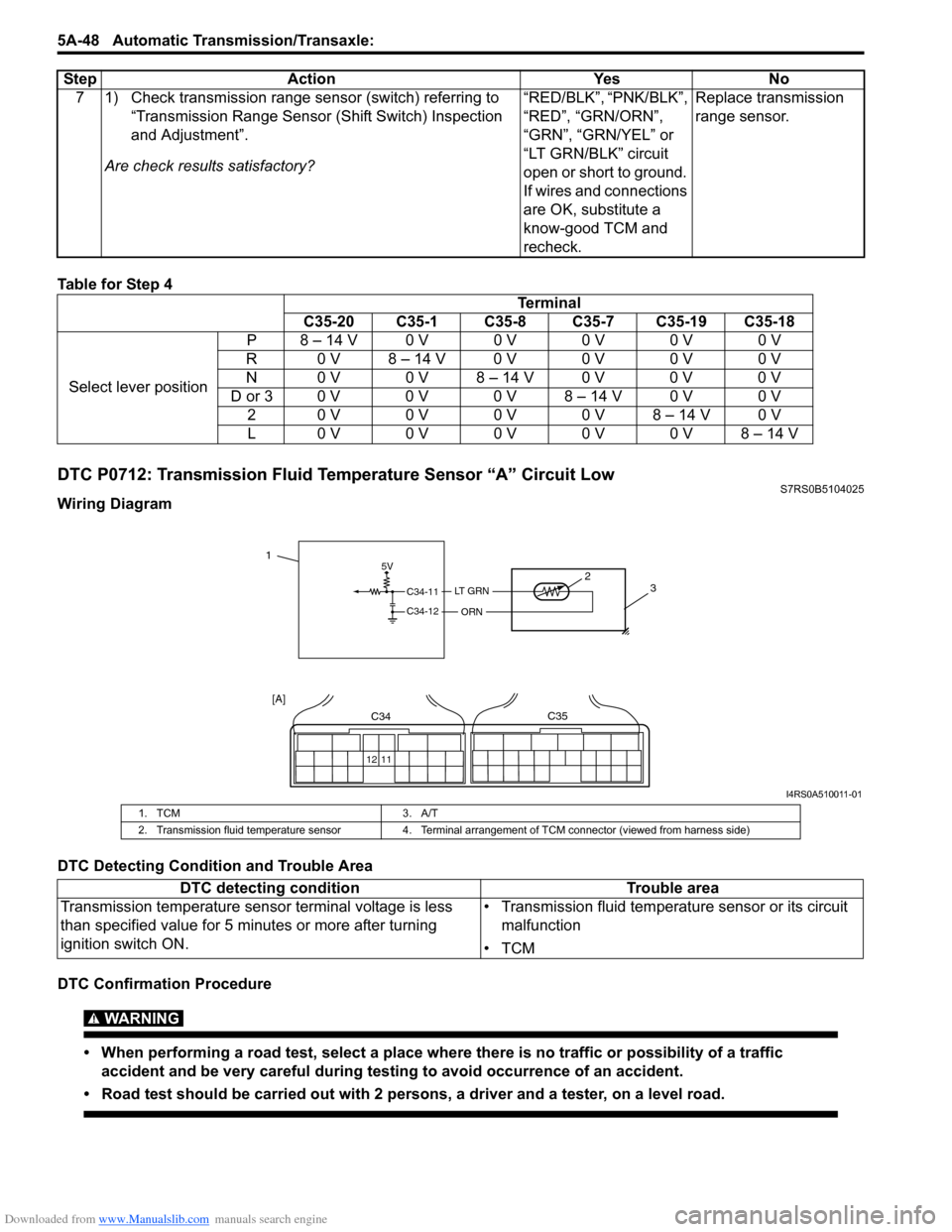
DTC P0712: Transmission Fluid Temperature Sensor “A” Circuit LowS7RS0B5104025
Wiring Diagram
DTC Detecting Condition and Trouble Area
DTC Confirmation Procedure
WARNING!
• When performing a road test, select a place where there is no traffic or possibility of a traffic
accident and be very careful during testing to avoid occurrence of an accident.
• Road test should be carried out with 2 persons, a driver and a tester, on a level road.
7 1) Check transmission range sensor (switch) referring to “Transmission Range Sensor (Shift Switch) Inspection
and Adjustment”.
Are check results satisfactory? “RED/BLK”, “PNK/BLK”,
“RED”, “GRN/ORN”,
“GRN”, “GRN/YEL” or
“LT GRN/BLK” circuit
open or short to ground.
If wires and connections
are OK, substitute a
know-good TCM and
recheck.Replace transmission
range sensor.
Step Action Yes No
Terminal
C35-20 C35-1 C35-8 C35-7 C35-19 C35-18
Select lever position P8 – 14 V0 V0 V0 V0 V0 V
R 0 V 8 – 14 V 0 V 0 V 0 V 0 V
N 0 V 0 V 8 – 14 V 0 V 0 V 0 V
D or 3 0 V 0 V 0 V 8 – 14 V 0 V 0 V 20 V0 V0 V0 V8 – 14 V0 V
L0 V0 V0 V0 V0 V8 – 14 V
5V
C34-11
C34-12
LT GRN
ORN
2 3
12 11
C34C35
[A]
1
I4RS0A510011-01
1. TCM 3. A/T
2. Transmission fluid temperature sensor 4. Terminal arrangement of TCM connector (viewed from harness side)
DTC detecting condition Trouble area
Transmission temperature sensor terminal voltage is less
than specified value for 5 minutes or more after turning
ignition switch ON. • Transmission fluid temperature sensor or its circuit
malfunction
•TCM
Page 696 of 1496
Downloaded from www.Manualslib.com manuals search engine 5A-52 Automatic Transmission/Transaxle:
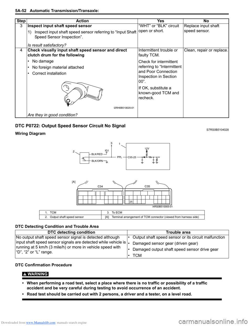
DTC P0722: Output Speed Sensor Circuit No SignalS7RS0B5104028
Wiring Diagram
DTC Detecting Condition and Trouble Area
DTC Confirmation Procedure
WARNING!
• When performing a road test, select a place where there is no traffic or possibility of a traffic
accident and be very careful during testing to avoid occurrence of an accident.
• Road test should be carried out with 2 persons, a driver and a tester, on a level road.
3 Inspect input shaft speed sensor
1) Inspect input shaft speed sensor referring to “Input Shaft
Speed Sensor Inspection”.
Is result satisfactory? “WHT” or “BLK” circuit
open or short.
Replace input shaft
speed sensor.
4 Check visually input shaft speed sensor and direct
clutch drum for the following
• No damage
• No foreign material attached
• Correct installation
Are they in good condition? Intermittent trouble or
faulty TCM.
Check for intermittent
referring to “Intermittent
and Poor Connection
Inspection in Section
00”.
If OK, substitute a
known-good TCM and
recheck.
Clean, repair or replace.
Step Action Yes No
I2RH0B510020-01
1. TCM
3. To ECM
2. Output shaft speed sensor [A]: Terminal arrangement of TCM connector (viewed from harness side)
DTC detecting condition Trouble area
No output shaft speed sensor signal is detected although
input shaft speed sensor signal s are detected while vehicle is
running at 5 km/h (3 mile/h) or more in vehicle speed with
“D”, “2” or “L” range. • Output shaft speed sensor or its circuit malfunction
• Damaged sensor gear (driven gear)
• Damaged output shaft speed sensor drive gear
•TCM
IG112V
PPLC35-25
2
C34
25
C35
[A]
1
BLK/RED
BLK/ORN
3
I4RS0B510005-01
Page 697 of 1496
Downloaded from www.Manualslib.com manuals search engine Automatic Transmission/Transaxle: 5A-53
1) Connect scan tool to DLC with ignition switch OFF, if available.
2) Clear DTC in TCM memory and start engine.
3) Shift select lever to “D” range and drive vehicle at 50 km /h (31 mile/h) or more vehicle speed at least for 3 minutes.
4) Stop vehicle and check DTC.
DTC Troubleshooting Step Action Yes No 1 Was “A/T System Check” performed? Go to Step 2. Go to “A/T System
Check”.
2 Check output shaft speed sensor power circuit
1) Turn ignition switch OFF.
2) Disconnect output shaft speed sensor connector.
3) Turn ignition switch ON.
4) Measure voltage between “BLK/RED” wire terminal of
disconnected output shaft speed sensor harness side
connector and ground.
Is it 10 – 14 V? Go to Step 3. “BLK/RED” wire open or
shorted to ground.
3 Check output shaft speed sensor ground circuit
1) Turn ignition switch OFF.
2) Check continuity between “BLK/ORN” wire terminal of
disconnected output shaft speed sensor harness side
connector and ground.
Is continuity indicated? Go to Step 4. “BLK/ORN” wire open.
4 Check output shaft speed sensor signal circuit for short
1) Disconnect TCM connectors.
2) Check continuity between “PPL” wire terminal of
disconnected output shaft speed sensor harness side
connector and ground.
Is continuity indicated? “PPL” wire shorted to
ground.
Go to Step 5.
5 Check output shaft speed sensor signal circuit for open
1) Check continuity between “PPL” wire terminal of
disconnected output shaft speed sensor harness side
connector and terminal “C35-25” of disconnected
harness side TCM connector.
Is continuity indicated? Go to Step 6. “PPL” wire open.
6 Inspect output shaft speed sensor
1) Inspect output shaft speed sensor referring to “Output
Shaft Speed Sensor Inspection”.
Is check result satisfactory? Go to Step 7. Replace output shaft
speed sensor.
7 Check output shaft speed sensor gears visually
1) Check output shaft speed sensor gears for the
followings.
• No damage in drive gear on differential case
• No damage in driven gear in output shaft speed sensor
Is result satisfactory? Intermittent trouble or
faulty TCM.
Check for intermittent
referring to “Intermittent
and Poor Connection
Inspection in Section
00”.
If OK, substitute a
known-good TCM and
recheck.Replace drive gear and/
or driven gear of output
shaft speed sensor.
Page 698 of 1496
Downloaded from www.Manualslib.com manuals search engine 5A-54 Automatic Transmission/Transaxle:
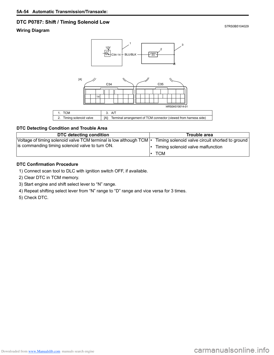
DTC P0787: Shift / Timing Solenoid LowS7RS0B5104029
Wiring Diagram
DTC Detecting Condition and Trouble Area
DTC Confirmation Procedure
1) Connect scan tool to DLC with ig nition switch OFF, if available.
2) Clear DTC in TCM memory.
3) Start engine and shift select lever to “N” range.
4) Repeat shifting select lever from “N” range to “D” range and vice versa for 3 times.
5) Check DTC.
1. TCM 3. A/T
2. Timing solenoid valve [A]: Terminal arrangement of TCM connector (viewed from harness side)
12V
C34-14BLU/BLK
31
2
14
C34C35
[A]
I4RS0A510014-01
DTC detecting condition Trouble area
Voltage of timing solenoid valve TCM terminal is low although TCM
is commanding timing sole noid valve to turn ON. • Timing solenoid valve circuit shorted to ground
• Timing solenoid valve malfunction
•TCM
Page 703 of 1496
Downloaded from www.Manualslib.com manuals search engine Automatic Transmission/Transaxle: 5A-59
DTC TroubleshootingStep Action Yes No 1 Was “A/T System Check” performed? Go to Step 2. Go to “A/T System
Check”.
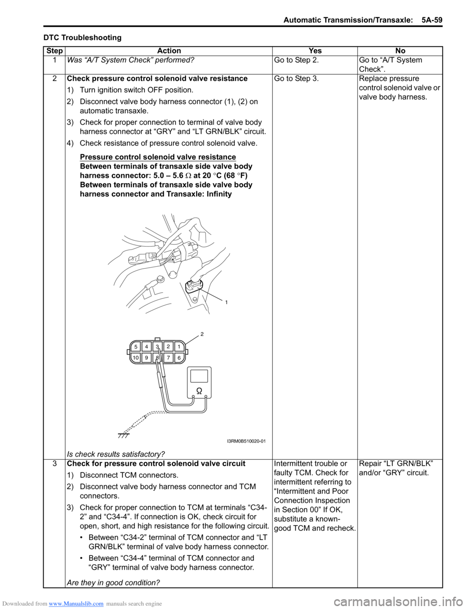
2 Check pressure control solenoid valve resistance
1) Turn ignition switch OFF position.
2) Disconnect valve body harness connector (1), (2) on
automatic transaxle.
3) Check for proper connection to terminal of valve body harness connector at “GRY” and “LT GRN/BLK” circuit.
4) Check resistance of pressure control solenoid valve.
Pressure control solenoid valve resistance
Between terminals of transaxle side valve body
harness connector: 5.0 – 5.6 Ω at 20 °C (68 °F)
Between terminals of transaxle side valve body
harness connector and Transaxle: Infinity
Is check results satisfactory? Go to Step 3. Replace pressure
control solenoid valve or
valve body harness.
3 Check for pressure control solenoid valve circuit
1) Disconnect TCM connectors.
2) Disconnect valve body harness connector and TCM
connectors.
3) Check for proper connection to TCM at terminals “C34- 2” and “C34-4”. If connection is OK, check circuit for
open, short, and high resistance for the following circuit.
• Between “C34-2” terminal of TCM connector and “LT GRN/BLK” terminal of valve body harness connector.
• Between “C34-4” terminal of TCM connector and “GRY” terminal of valve body harness connector.
Are they in good condition? Intermittent trouble or
faulty TCM. Check for
intermittent referring to
“Intermittent and Poor
Connection Inspection
in Section 00” If OK,
substitute a known-
good TCM and recheck.
Repair “LT GRN/BLK”
and/or “GRY” circuit.
1
6
7
89
10 5
43 2
1
2
I3RM0B510020-01
Page 704 of 1496
Downloaded from www.Manualslib.com manuals search engine 5A-60 Automatic Transmission/Transaxle:
DTC P0962: Pressure Control Solenoid “A” Control Circuit LowS7RS0B5104031
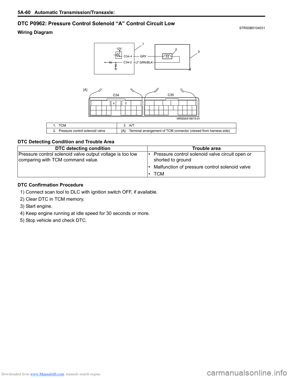
Wiring Diagram
DTC Detecting Condition and Trouble Area
DTC Confirmation Procedure
1) Connect scan tool to DLC with ig nition switch OFF, if available.
2) Clear DTC in TCM memory.
3) Start engine.
4) Keep engine running at idle speed for 30 seconds or more.
5) Stop vehicle and check DTC.
1. TCM 3. A/T
2. Pressure control solenoid valve [A]: Terminal arrangement of TCM connector (viewed from harness side)
DTC detecting condition Trouble area
Pressure control solenoid valv e output voltage is too low
comparing with TCM command value. • Pressure control solenoid valve circuit open or
shorted to ground
• Malfunction of pressure control solenoid valve
•TCM
12V
C34-4
C34-2
GRY
LT GRN/BLK
3
1
2
42
C34C35
[A]
I4RS0A510015-01
Page 708 of 1496
Downloaded from www.Manualslib.com manuals search engine 5A-64 Automatic Transmission/Transaxle:
DTC P0973 / P0976: Shift Solenoid “A” Control Circuit Low / Shift Solenoid “B” Control Circuit LowS7RS0B5104033
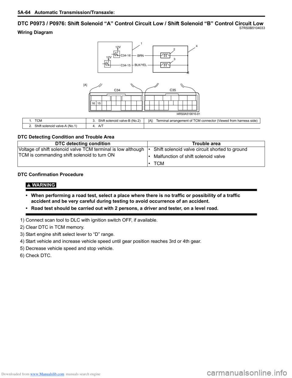
Wiring Diagram
DTC Detecting Condition and Trouble Area
DTC Confirmation Procedure
WARNING!
• When performing a road test, select a place where there is no traffic or possibility of a traffic
accident and be very careful during testing to avoid occurrence of an accident.
• Road test should be carried out with 2 persons, a driver and tester, on a level road.
1) Connect scan tool to DLC with ig nition switch OFF, if available.
2) Clear DTC in TCM memory.
3) Start engine shift select lever to “D” range.
4) Start vehicle and increase vehicle speed until gear position reaches 3rd or 4th gear.
5) Decrease vehicle sp eed and stop vehicle.
6) Check DTC.
1. TCM 3. Shift solenoid valve-B (No.2) [A]: Terminal arr angement of TCM connector (Viewed from harness side)
2. Shift solenoid valve-A (No.1) 4. A/T
DTC detecting condition Trouble area
Voltage of shift solenoid valv e TCM terminal is low although
TCM is commanding shift solenoid to turn ON • Shift solenoid valve circuit shorted to ground
• Malfunction of shift solenoid valve
•TCM
12V
12VBRNC34-16
C34-15BLK/YEL
41
2
3
16 15
C34C35
[A]
I4RS0A510016-01
Page 709 of 1496
Downloaded from www.Manualslib.com manuals search engine Automatic Transmission/Transaxle: 5A-65
DTC TroubleshootingStep Action Yes No 1 Was “Automatic Transaxle Diagnostic Flow Table”
performed? Go to Step 2. Go to “A/T System
Check”.
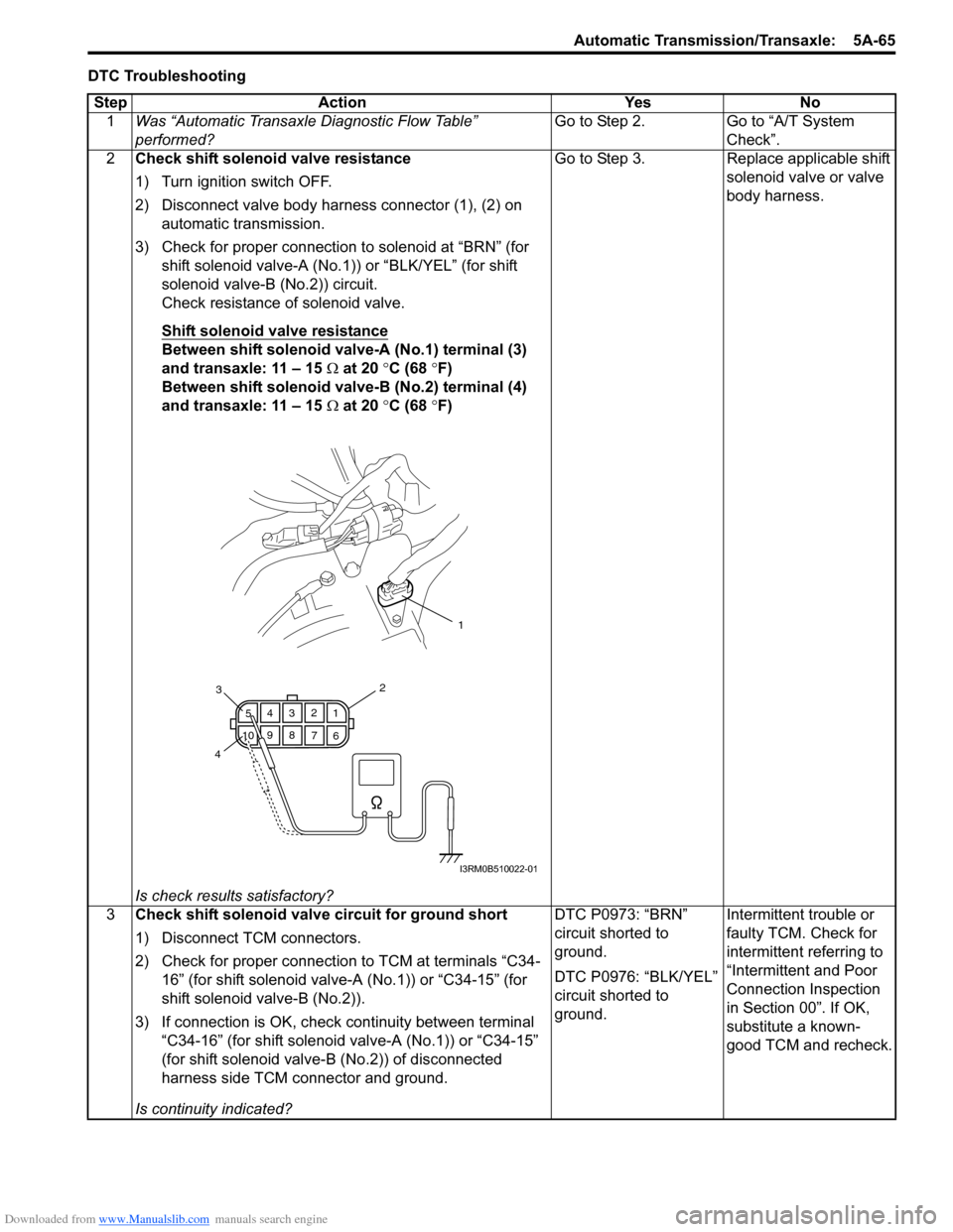
2 Check shift solenoid valve resistance
1) Turn ignition switch OFF.
2) Disconnect valve body harness connector (1), (2) on
automatic transmission.
3) Check for proper connection to solenoid at “BRN” (for shift solenoid valve-A (No.1)) or “BLK/YEL” (for shift
solenoid valve-B (No.2)) circuit.
Check resistance of solenoid valve.
Shift solenoid valve resistance
Between shift solenoid valve-A (No.1) terminal (3)
and transaxle: 11 – 15 Ω at 20 °C (68 °F)
Between shift solenoid valve-B (No.2) terminal (4)
and transaxle: 11 – 15 Ω at 20 °C (68 °F)
Is check results satisfactory? Go to Step 3. Replace applicable shift
solenoid valve or valve
body harness.
3 Check shift solenoid valve circuit for ground short
1) Disconnect TCM connectors.
2) Check for proper connection to TCM at terminals “C34-
16” (for shift solenoid valve-A (No.1)) or “C34-15” (for
shift solenoid valve-B (No.2)).
3) If connection is OK, check continuity between terminal
“C34-16” (for shift solenoid valve-A (No.1)) or “C34-15”
(for shift solenoid valve-B (No.2)) of disconnected
harness side TCM connector and ground.
Is continuity indicated? DTC P0973: “BRN”
circuit shorted to
ground.
DTC P0976: “BLK/YEL”
circuit shorted to
ground.
Intermittent trouble or
faulty TCM. Check for
intermittent referring to
“Intermittent and Poor
Connection Inspection
in Section 00”. If OK,
substitute a known-
good TCM and recheck.
1
6
7
89
10 5
43 2
1
23
4
I3RM0B510022-01
Page 712 of 1496
Downloaded from www.Manualslib.com manuals search engine 5A-68 Automatic Transmission/Transaxle:
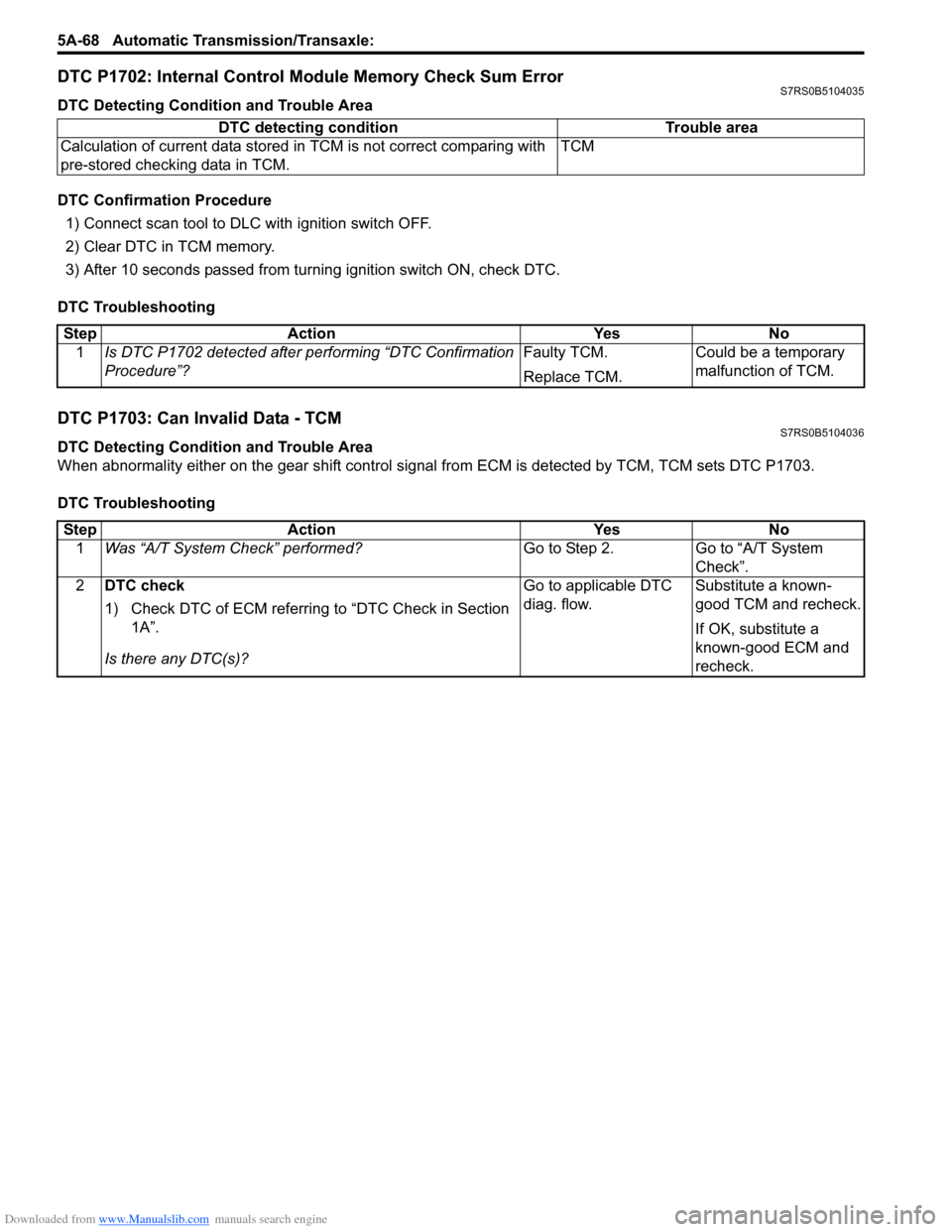
DTC P1702: Internal Control Module Memory Check Sum ErrorS7RS0B5104035
DTC Detecting Condition and Trouble Area
DTC Confirmation Procedure
1) Connect scan tool to DLC with ignition switch OFF.
2) Clear DTC in TCM memory.
3) After 10 seconds passed from turning ignition switch ON, check DTC.
DTC Troubleshooting
DTC P1703: Can Invalid Data - TCMS7RS0B5104036
DTC Detecting Condition and Trouble Area
When abnormality either on the gear shift control signal from ECM is detected by TCM, TCM sets DTC P1703.
DTC Troubleshooting DTC detecting condition Trouble area
Calculation of current data stored in TCM is not correct comparing with
pre-stored checking data in TCM. TCM
Step
Action YesNo
1 Is DTC P1702 detected after performing “DTC Confirmation
Procedure”? Faulty TCM.
Replace TCM.Could be a temporary
malfunction of TCM.
Step
Action YesNo
1 Was “A/T System Check” performed? Go to Step 2.Go to “A/T System
Check”.
2 DTC check
1) Check DTC of ECM referring to “DTC Check in Section
1A”.
Is there any DTC(s)? Go to applicable DTC
diag. flow.
Substitute a known-
good TCM and recheck.
If OK, substitute a
known-good ECM and
recheck.
Page 716 of 1496
Downloaded from www.Manualslib.com manuals search engine 5A-72 Automatic Transmission/Transaxle:
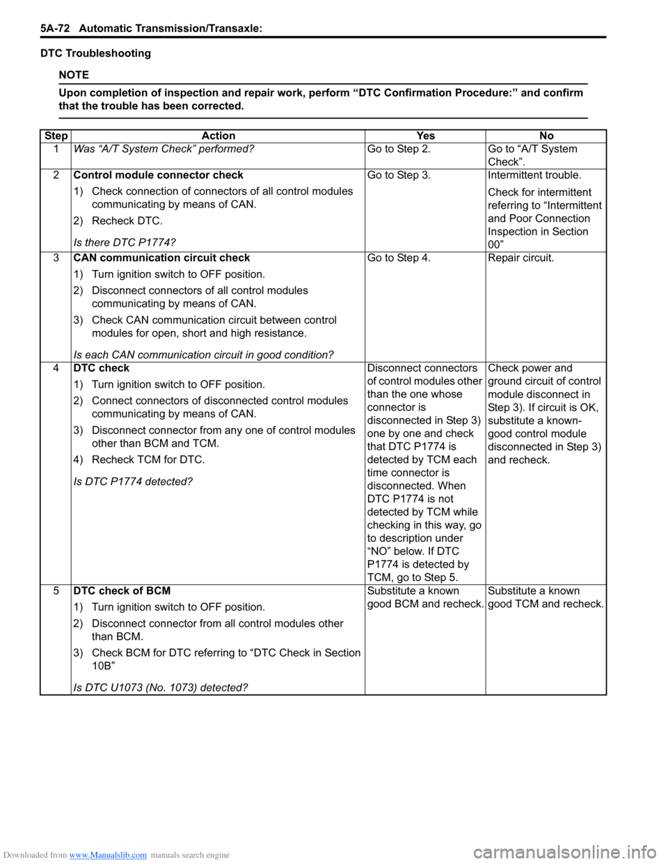
DTC Troubleshooting
NOTE
Upon completion of inspection and repair work, perform “DTC Confirmation Procedure:” and confirm
that the trouble has been corrected.
Step Action YesNo
1 Was “A/T System Check” performed? Go to Step 2.Go to “A/T System
Check”.
2 Control module connector check
1) Check connection of connectors of all control modules
communicating by means of CAN.
2) Recheck DTC.
Is there DTC P1774? Go to Step 3.
Intermittent trouble.
Check for intermittent
referring to “Intermittent
and Poor Connection
Inspection in Section
00”
3 CAN communication circuit check
1) Turn ignition switch to OFF position.
2) Disconnect connectors of all control modules
communicating by means of CAN.
3) Check CAN communication circuit between control modules for open, short and high resistance.
Is each CAN communication circuit in good condition? Go to Step 4.
Repair circuit.
4 DTC check
1) Turn ignition switch to OFF position.
2) Connect connectors of disconnected control modules
communicating by means of CAN.
3) Disconnect connector from any one of control modules other than BCM and TCM.
4) Recheck TCM for DTC.
Is DTC P1774 detected? Disconnect connectors
of control modules other
than the one whose
connector is
disconnected in Step 3)
one by one and check
that DTC P1774 is
detected by TCM each
time connector is
disconnected. When
DTC P1774 is not
detected by TCM while
checking in this way, go
to description under
“NO” below. If DTC
P1774 is detected by
TCM, go to Step 5.Check power and
ground circuit of control
module disconnect in
Step 3). If circuit is OK,
substitute a known-
good control module
disconnected in Step 3)
and recheck.
5 DTC check of BCM
1) Turn ignition switch to OFF position.
2) Disconnect connector from all control modules other
than BCM.
3) Check BCM for DTC referring to “DTC Check in Section 10B”
Is DTC U1073 (No. 1073) detected? Substitute a known
good BCM and recheck.
Substitute a known
good TCM and recheck.