Engine mount bracket SUZUKI SWIFT 2007 2.G Service Service Manual
[x] Cancel search | Manufacturer: SUZUKI, Model Year: 2007, Model line: SWIFT, Model: SUZUKI SWIFT 2007 2.GPages: 1496, PDF Size: 34.44 MB
Page 1041 of 1496
Downloaded from www.Manualslib.com manuals search engine Air Bag System: 8B-3
• Never attempt disassembly of the air bag (inflator) modules.
• If any abnormality is found, be sure to replace it with
new one as an assembly.
• When an abnormality is noted as existing in the live (undeployed) air bag (inflator) module, be sure to
deploy it before discarding it.
• When grease, cleaning agent, oil, water, etc., got on the air bag (inflator) modules (driver, passenger, side
of both sides and curtain of both sides), wipe it off
immediately with a dry cloth.
• If air bag (inflator) module was dropped from a height of 90 cm (3 ft) or more, it should be replaced with a
new one as an assembly.
WARNING!
• For handling and storage of a live air bag (inflator) module, select a place where the
ambient temperature below 65 °C (150 ° F),
without high humidity and away from
electric noise.
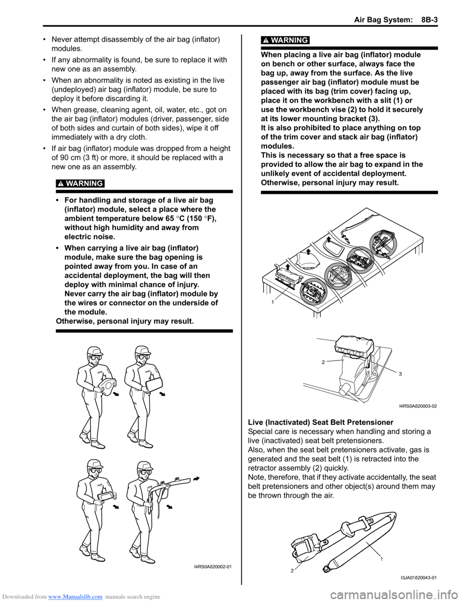
• When carrying a live air bag (inflator) module, make sure the bag opening is
pointed away from you. In case of an
accidental deployment, the bag will then
deploy with minimal chance of injury.
Never carry the air bag (inflator) module by
the wires or connector on the underside of
the module.
Otherwise, personal injury may result.
WARNING!
When placing a live air bag (inflator) module
on bench or other surface, always face the
bag up, away from the surface. As the live
passenger air bag (inflator) module must be
placed with its bag (trim cover) facing up,
place it on the workbench with a slit (1) or
use the workbench vise (2) to hold it securely
at its lower mounting bracket (3).
It is also prohibited to place anything on top
of the trim cover and stack air bag (inflator)
modules.
This is necessary so that a free space is
provided to allow the air bag to expand in the
unlikely event of accidental deployment.
Otherwise, personal injury may result.
Live (Inactivated) Seat Belt Pretensioner
Special care is necessary when handling and storing a
live (inactivated) seat belt pretensioners.
Also, when the seat belt pretensioners activate, gas is
generated and the seat belt (1) is retracted into the
retractor assembly (2) quickly.
Note, therefore, that if they activate accidentally, the seat
belt pretensioners and other object(s) around them may
be thrown through the air.
I4RS0A820002-01
1
2
3
I4RS0A820003-02
I3JA01820043-01
Page 1134 of 1496
Downloaded from www.Manualslib.com manuals search engine 8B-96 Air Bag System:
Repair and Inspection Required after AccidentS7RS0B8204049
CAUTION!
• All air bag system components, including the electrical harness (component
mounting points), must be inspected after
an accident. If any components are
damaged or bent, they must be replaced
even if air bag system activation did not
occur.
• Never use air bag system parts from another vehicle.
• Do not attempt to service the parts below. Service of these parts is by replacement
only.
– Driver / Passenger air bag (inflator) modules
– Driver / Passenger side-air bag (inflator) modules
– Driver / Passenger side curtain-air bag (inflator) modules
– Driver / Passenger seat belt pretensioners
–Forward-sensor
– Driver / Passenger side-sensors
–SDM
– Contact coil and combination switch assembly
– Air bag wire harness in main harness, instrument panel harness and floor
harness.
• Proper operation of the sensors and air bag system requires that any repairs to the
vehicle structure return it to its original
production configuration.
CAUTION!
After detecting one time of such collision as
to meet deployment conditions, the SDM
must not be used.
Refer to “Air Bag Diagnostic System Check”
when checking the SDM.
Accident with Deployment / Activation – Component
Replacement
When driver and passenger air bags are deployed, the
following components must be replaced.
• Driver and passenger air bag (inflator) modules
• Driver and passenger seat belt pretensioners
• SDM after detecting such collision as to meet
deployment conditions
• Forward-sensor
• Instrument panel When side-air bag and side curtain-air bag are deployed,
the following components must be replaced.
• Deployed side-air bag (inflator) module
• Deployed side curtain-air bag (inflator) module
• Side-sensor
•SDM
Accident with or without Deployment / Activation –
Component Inspections
Certain air bag and restraint system components must
be inspected after any crash, whether the air bag system
activated or not. If any faul
ty condition is found in the
following checks, replace faulty part.
Those components are:
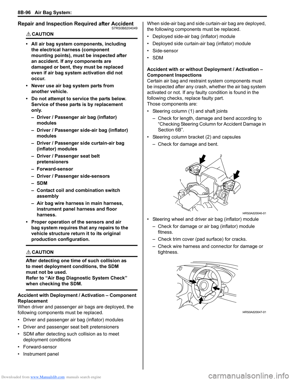
• Steering column (1) and shaft joints
– Check for length, damage and bend according to “Checking Steering Column for Accident Damage in
Section 6B”.
• Steering column bracket (2) and capsules – Check for damage and bent.
• Steering wheel and driver air bag (inflator) module – Check for damage or air bag (inflator) module fitness.
– Check trim cover (pad surface) for cracks.
– Check wire harness and connector for damage or tightness.
2
1
I4RS0A820046-01
I4RS0A820047-01
Page 1142 of 1496
Downloaded from www.Manualslib.com manuals search engine 8B-104 Air Bag System:
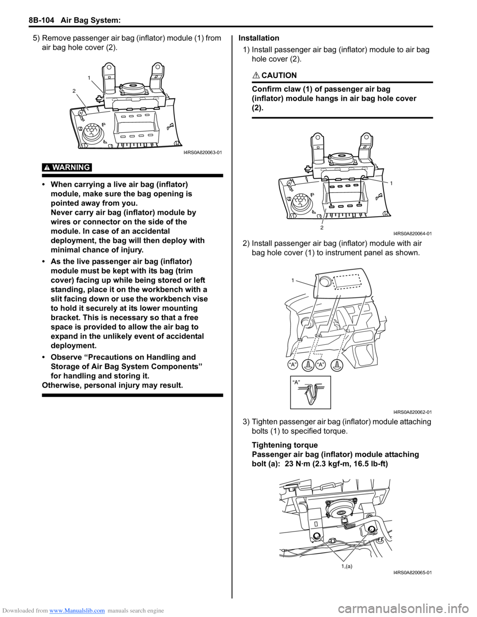
5) Remove passenger air bag (inflator) module (1) from air bag hole cover (2).
WARNING!
• When carrying a live air bag (inflator) module, make sure the bag opening is
pointed away from you.
Never carry air bag (inflator) module by
wires or connector on the side of the
module. In case of an accidental
deployment, the bag will then deploy with
minimal chance of injury.
• As the live passenger air bag (inflator) module must be kept with its bag (trim
cover) facing up while being stored or left
standing, place it on the workbench with a
slit facing down or use the workbench vise
to hold it securely at its lower mounting
bracket. This is necessary so that a free
space is provided to allow the air bag to
expand in the unlikely event of accidental
deployment.
• Observe “Precautions on Handling and Storage of Air Bag System Components”
for handling and storing it.
Otherwise, personal injury may result.
Installation
1) Install passenger air bag (inflator) module to air bag hole cover (2).
CAUTION!
Confirm claw (1) of passenger air bag
(inflator) module hangs in air bag hole cover
(2).
2) Install passenger air bag (inflator) module with air bag hole cover (1) to instrument panel as shown.
3) Tighten passenger air bag (inflator) module attaching bolts (1) to sp ecified torque.
Tightening torque
Passenger air bag (inflator) module attaching
bolt (a): 23 N·m (2.3 kgf-m, 16.5 lb-ft)
1
2
I4RS0A820063-01
2 1I4RS0A820064-01
“A”
“A”“A”
1
I4RS0A820062-01
1,(a)I4RS0A820065-01
Page 1147 of 1496
Downloaded from www.Manualslib.com manuals search engine Air Bag System: 8B-109
Side Curtain-Air Bag (Inflator) Module
Inspection
S7RS0B8206012
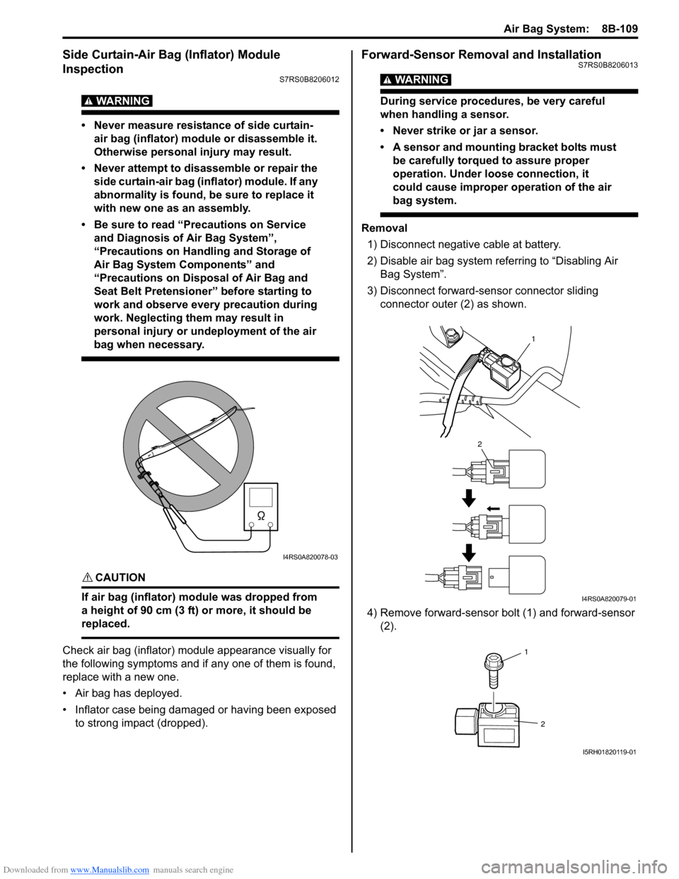
WARNING!
• Never measure resistance of side curtain-air bag (inflator) module or disassemble it.
Otherwise personal injury may result.
• Never attempt to disassemble or repair the side curtain-air bag (inflator) module. If any
abnormality is found, be sure to replace it
with new one as an assembly.
• Be sure to read “Precautions on Service and Diagnosis of Air Bag System”,
“Precautions on Handling and Storage of
Air Bag System Components” and
“Precautions on Disposal of Air Bag and
Seat Belt Pretensioner” before starting to
work and observe every precaution during
work. Neglecting them may result in
personal injury or undeployment of the air
bag when necessary.
CAUTION!
If air bag (inflator) module was dropped from
a height of 90 cm (3 ft) or more, it should be
replaced.
Check air bag (inflator) module appearance visually for
the following symptoms and if any one of them is found,
replace with a new one.
• Air bag has deployed.
• Inflator case being damaged or having been exposed to strong impact (dropped).
Forward-Sensor Removal and InstallationS7RS0B8206013
WARNING!
During service procedures, be very careful
when handling a sensor.
• Never strike or jar a sensor.
• A sensor and mounting bracket bolts must be carefully torqued to assure proper
operation. Under loose connection, it
could cause improper operation of the air
bag system.
Removal
1) Disconnect negative cable at battery.
2) Disable air bag system referring to “Disabling Air Bag System”.
3) Disconnect forward-sensor connector sliding connector outer (2) as shown.
4) Remove forward-sensor bolt (1) and forward-sensor (2).
I4RS0A820078-03
1
2
I4RS0A820079-01
1
2
I5RH01820119-01
Page 1148 of 1496
Downloaded from www.Manualslib.com manuals search engine 8B-110 Air Bag System:
Installation
CAUTION!
Proper operation of forward-sensor requires
sensor be rigidly attached to vehicle
structure and that the arrow on sensor be
pointing toward the front of the vehicle.
1) Check that none of the following faulty conditions exists.
• Bend, deformity or rust of front panel.
• Foreign matter on mating surface of sensor.
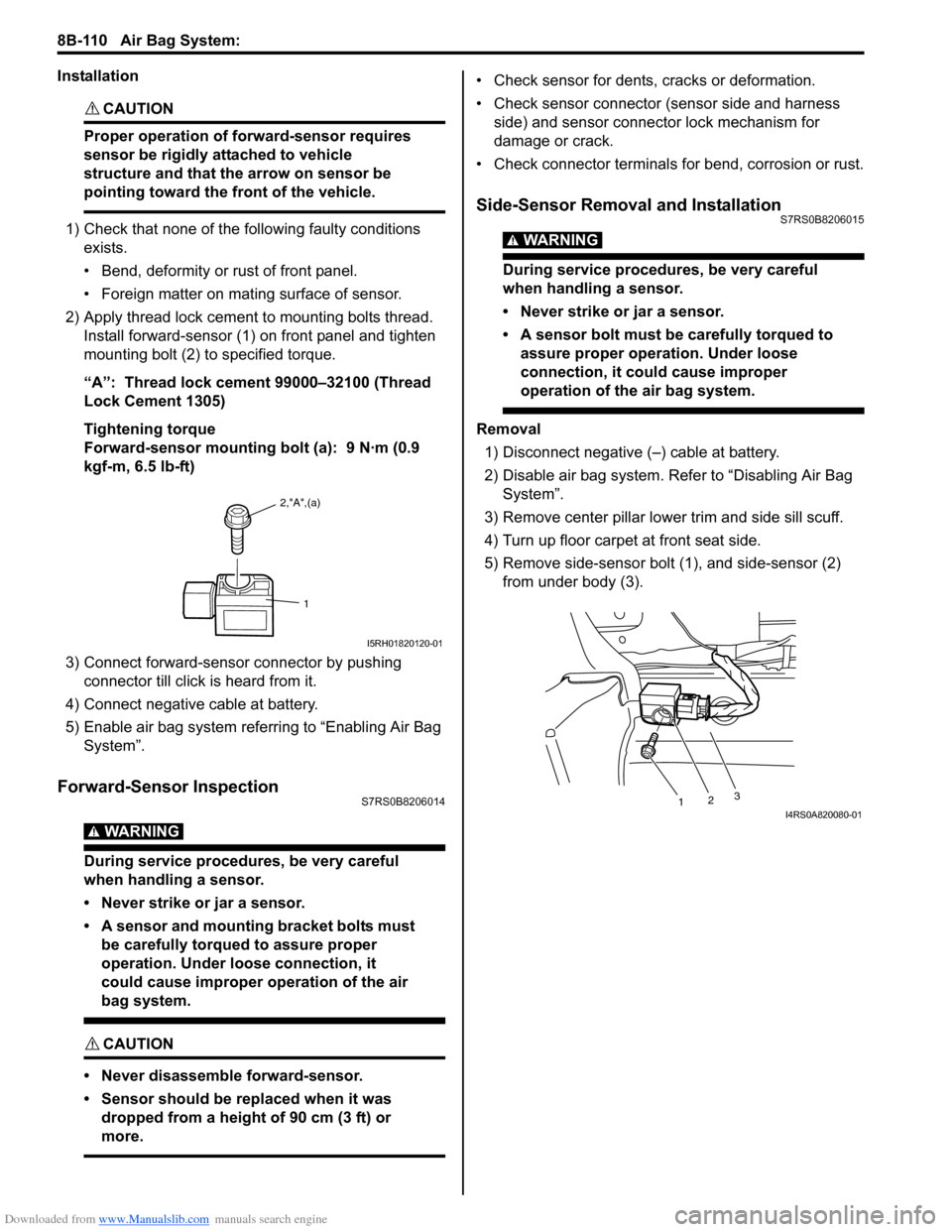
2) Apply thread lock cement to mounting bolts thread. Install forward-sensor (1) on front panel and tighten
mounting bolt (2) to specified torque.
“A”: Thread lock cement 99000–32100 (Thread
Lock Cement 1305)
Tightening torque
Forward-sensor mounting bolt (a): 9 N·m (0.9
kgf-m, 6.5 lb-ft)
3) Connect forward-sensor connector by pushing connector till click is heard from it.
4) Connect negative cable at battery.
5) Enable air bag system referring to “Enabling Air Bag System”.
Forward-Sensor InspectionS7RS0B8206014
WARNING!
During service procedures, be very careful
when handling a sensor.
• Never strike or jar a sensor.
• A sensor and mounting bracket bolts must be carefully torqued to assure proper
operation. Under loose connection, it
could cause improper operation of the air
bag system.
CAUTION!
• Never disassemble forward-sensor.
• Sensor should be replaced when it was dropped from a height of 90 cm (3 ft) or
more.
• Check sensor for dents, cracks or deformation.
• Check sensor connector (sensor side and harness side) and sensor connector lock mechanism for
damage or crack.
• Check connector terminals for bend, corrosion or rust.
Side-Sensor Removal and InstallationS7RS0B8206015
WARNING!
During service procedures, be very careful
when handling a sensor.
• Never strike or jar a sensor.
• A sensor bolt must be carefully torqued to assure proper operation. Under loose
connection, it could cause improper
operation of the air bag system.
Removal
1) Disconnect negative (–) cable at battery.
2) Disable air bag system. Re fer to “Disabling Air Bag
System”.
3) Remove center pillar lowe r trim and side sill scuff.
4) Turn up floor carpet at front seat side.
5) Remove side-sensor bolt (1), and side-sensor (2) from under body (3).
2,"A",(a)
1
I5RH01820120-01
1 23I4RS0A820080-01
Page 1149 of 1496

Downloaded from www.Manualslib.com manuals search engine Air Bag System: 8B-111
6) Disconnect side-sensor connector sliding connector
outer (1) as shown.
Installation
CAUTION!
Proper operation of side-sensor requires
sensor be rigidly attached to specified
position.
1) Check that none of following faulty conditions exists.
• Bend, deformity or rust of under body.
• Foreign matter on mating surface of sensor.
2) Install side-sensor (1) on under body (2) and tighten side-sensor bolt (3) to specified torque.
Tightening torque
Side-sensor bolt (a): 9 N·m (0.9 kgf-m, 6.5 lb-ft) 3) Connect side-sensor connector pushing connector
inner (1) as shown.
4) Connect negative cable at battery.
5) Enable air bag system. Refer to “Enabling Air Bag System”.
Side-Sensor InspectionS7RS0B8206016
WARNING!
During service procedures, be very careful
when handling a sensor.
• Never strike or jar a sensor.
• A sensor and mounting bracket bolts must be carefully torqued to assure proper
operation. Under loose connection, it
could cause improper operation of the air
bag system.
CAUTION!
• Never disassemble side-sensor.
• Sensor should be replaced when it was dropped from a height of 90 cm (3 ft) or
more.
1
1
I4RS0A820109-01
1 2
3, (a)I4RS0A820081-01
1
1
I4RS0A820106-01
Page 1152 of 1496
Downloaded from www.Manualslib.com manuals search engine 8B-114 Air Bag System:
Deployment / Activation Outside of Vehicle
When you intend to return the vehicle to service, deploy
the air bag (inflator) module(s) or activate seat belt
pretensioner(s) outside of the vehicle.1) Turn ignition switch to LOCK position and remove key.
2) Wear safety glasses during this deployment / activation procedure.
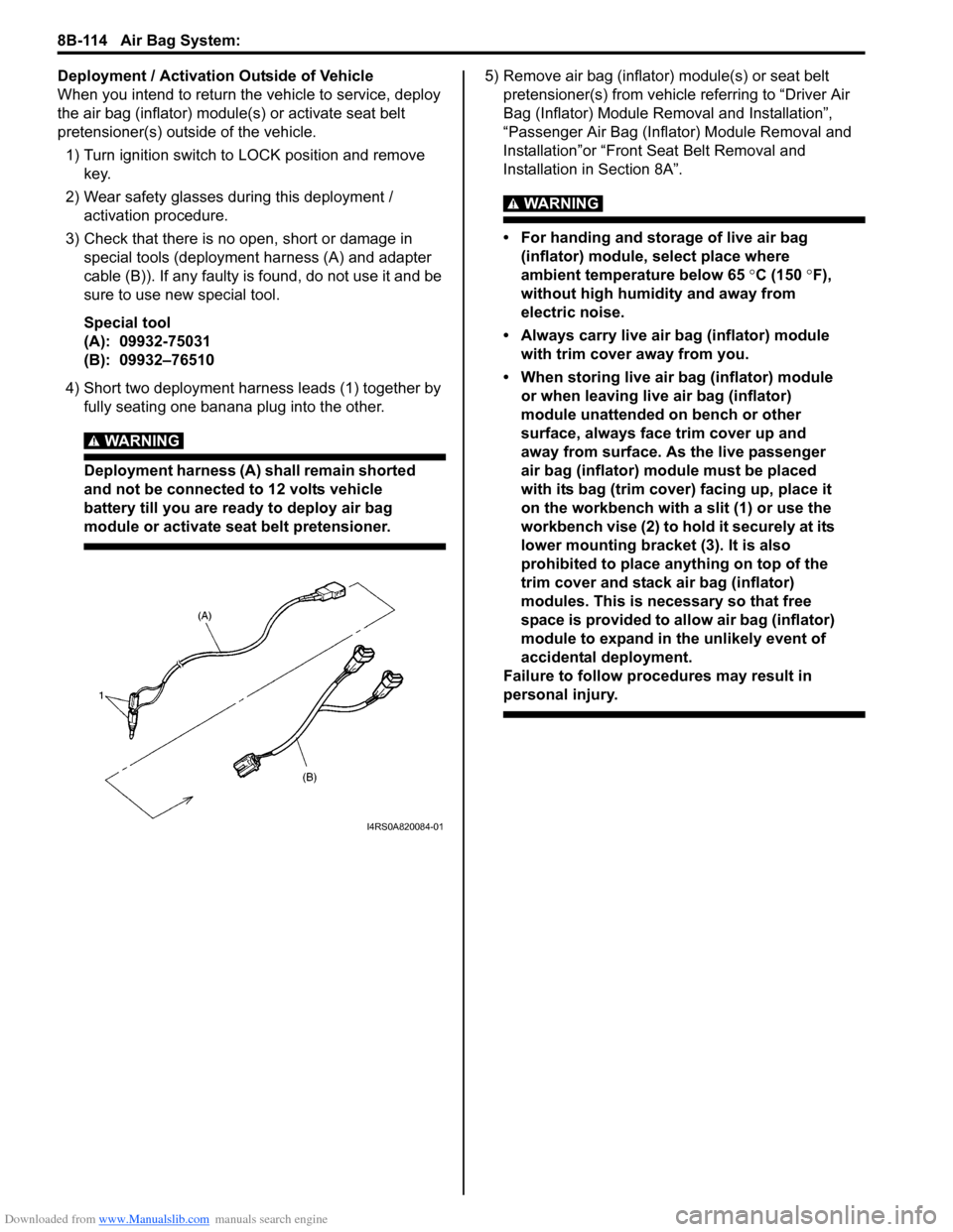
3) Check that there is no open, short or damage in special tools (deployment harness (A) and adapter
cable (B)). If any faulty is found, do not use it and be
sure to use new special tool.
Special tool
(A): 09932-75031
(B): 09932–76510
4) Short two deployment harness leads (1) together by fully seating one banana plug into the other.
WARNING!
Deployment harness (A) shall remain shorted
and not be connected to 12 volts vehicle
battery till you are ready to deploy air bag
module or activate seat belt pretensioner.
5) Remove air bag (inflator) module(s) or seat belt pretensioner(s) from vehicle referring to “Driver Air
Bag (Inflator) Module Re moval and Installation”,
“Passenger Air Bag (Inflator) Module Removal and
Installation”or “Front Seat Belt Removal and
Installation in Section 8A”.
WARNING!
• For handing and storage of live air bag (inflator) module, select place where
ambient temperature below 65 °C (150 °F),
without high humidity and away from
electric noise.
• Always carry live air bag (inflator) module with trim cover away from you.
• When storing live air bag (inflator) module or when leaving live air bag (inflator)
module unattended on bench or other
surface, always face trim cover up and
away from surface. As the live passenger
air bag (inflator) module must be placed
with its bag (trim cover) facing up, place it
on the workbench with a slit (1) or use the
workbench vise (2) to hold it securely at its
lower mounting bracket (3). It is also
prohibited to place anything on top of the
trim cover and stack air bag (inflator)
modules. This is necessary so that free
space is provided to allow air bag (inflator)
module to expand in the unlikely event of
accidental deployment.
Failure to follow procedures may result in
personal injury.
I4RS0A820084-01
Page 1153 of 1496
Downloaded from www.Manualslib.com manuals search engine Air Bag System: 8B-115
WARNING!
• For handling and storage of seat belt pretensioner, select place where ambient
temperature is below 65 °C (150 °F),
without high humidity and away from
electric noise.
• Never carry seat belt pretensioner by webbing.
• When placing seat belt pretensioner on workbench or other surface, be sure to lay
it with its exhaust hole (1) side facing up. It
is also prohibited to put something on seat
belt pretensioner.
Otherwise, personal injury may result.
6) Set air bag (inflator) module or seat belt pretensioner
as follows.
• For driver air bag (inflator) module
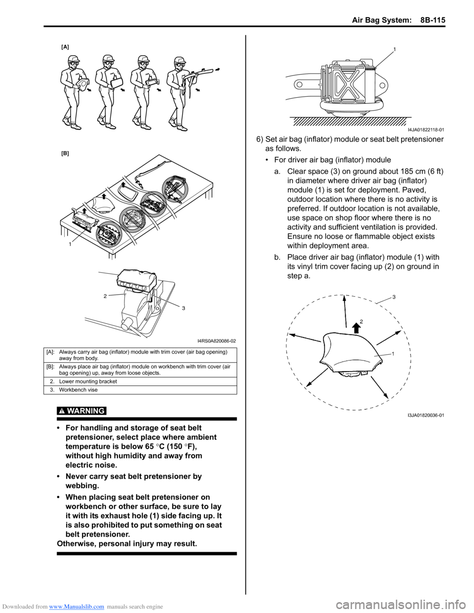
a. Clear space (3) on ground about 185 cm (6 ft) in diameter where driver air bag (inflator)
module (1) is set for deployment. Paved,
outdoor location where there is no activity is
preferred. If outdoor location is not available,
use space on shop floor where there is no
activity and sufficient ventilation is provided.
Ensure no loose or flammable object exists
within deployment area.
b. Place driver air bag (inflator) module (1) with its vinyl trim cover facing up (2) on ground in
step a.
[A]: Always carry air bag (inflator) module with trim cover (air bag opening) away from body.
[B]: Always place air bag (inflator) module on workbench with trim cover (air bag opening) up, away from loose objects.
2. Lower mounting bracket
3. Workbench vise
1
2
3
[A]
[B]
I4RS0A820086-02
1
I4JA01822118-01
I3JA01820036-01
Page 1313 of 1496
Downloaded from www.Manualslib.com manuals search engine Instrumentation / Driver Info. / Horn: 9C-18
Instrument Panel Removal and InstallationS7RS0B9306015
WARNING!
Refer to “Air Bag Warning in Section 00”
before starting service work.
Removal
1) Disconnect negative (–) cable at battery.
2) Disable air bag system referring to “Disabling Air Bag System in Section 8B”.
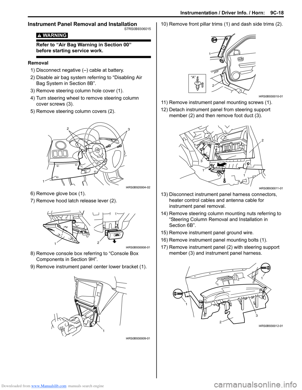
3) Remove steering column hole cover (1).
4) Turn steering wheel to remove steering column cover screws (3).
5) Remove steering column covers (2).
6) Remove glove box (1).
7) Remove hood latch release lever (2).
8) Remove console box referring to “Console Box Components in Section 9H”.
9) Remove instrument panel center lower bracket (1). 10) Remove front pillar trims
(1) and dash side trims (2).
11) Remove instrument panel mounting screws (1).
12) Detach instrument panel from steering support member (2) and then remove foot duct (3).
13) Disconnect instrument panel harness connectors, heater control cables and antenna cable for
instrument panel removal.
14) Remove steering column mounting nuts referring to “Steering Column Remova l and Installation in
Section 6B”.
15) Remove instrument panel ground wire.
16) Remove instrument panel mounting bolts (1).
17) Remove instrument panel (2) with steering support member (3) and instrument panel harness.
1
32
I4RS0B920004-02
2
1I4RS0B930008-01
1
I4RS0B930009-01
“A”
“A”
1
2
I4RS0B930010-01
1
1 2
3
I4RS0B930011-01
1 1
2
3I4RS0B930012-01
Page 1335 of 1496
Downloaded from www.Manualslib.com manuals search engine Glass / Windows / Mirrors: 9E-8
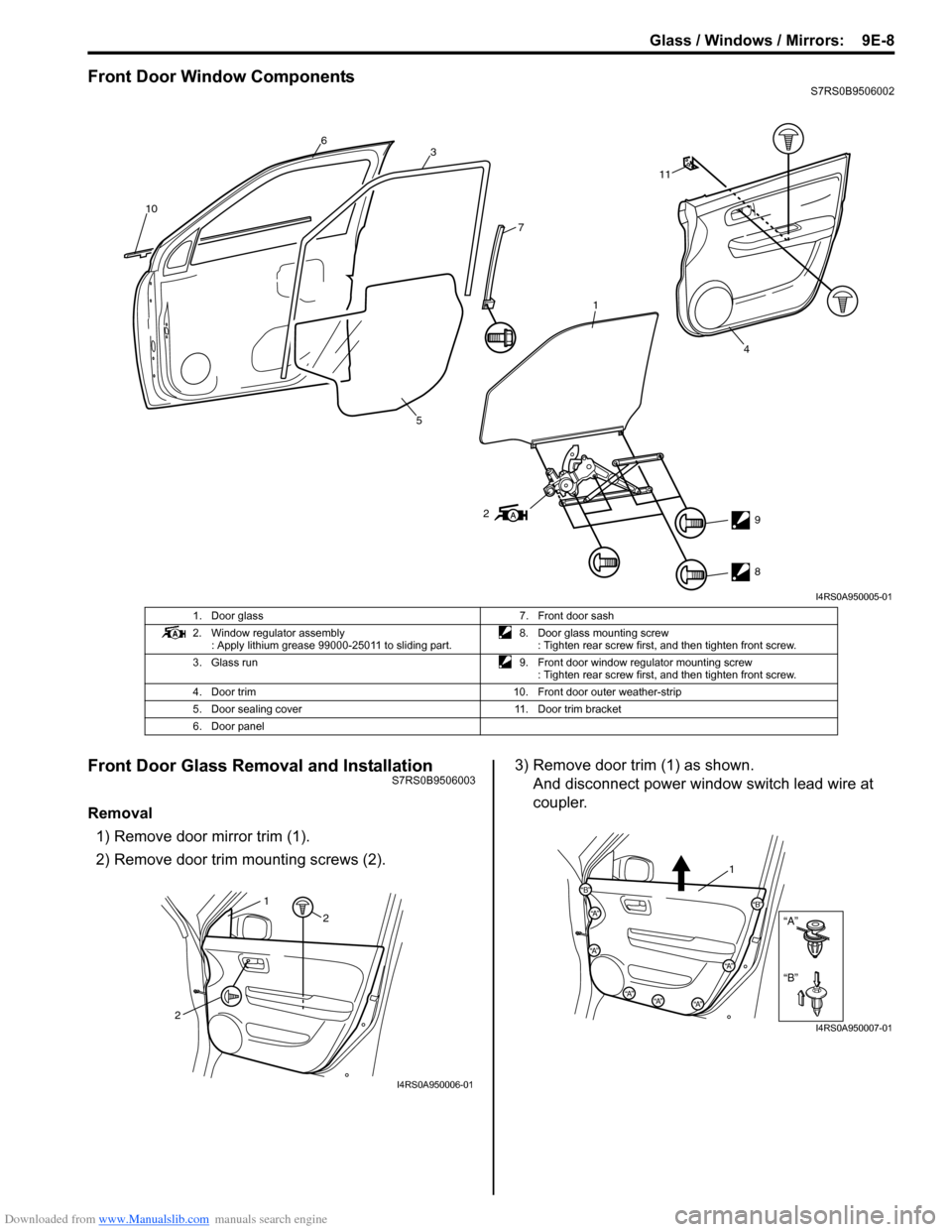
Front Door Window ComponentsS7RS0B9506002
Front Door Glass Removal and InstallationS7RS0B9506003
Removal1) Remove door mirror trim (1).
2) Remove door trim mounting screws (2). 3) Remove door trim (1) as shown.
And disconnect power window switch lead wire at
coupler.
10 6
3
1
7
11
5
2 9
8
4
I4RS0A950005-01
1. Door glass 7. Front door sash
2. Window regulator assembly : Apply lithium grease 99000-25011 to sliding part. 8. Door glass mounting screw
: Tighten rear screw first, and then tighten front screw.
3. Glass run 9. Front door window regulator mounting screw
: Tighten rear screw first, and then tighten front screw.
4. Door trim 10. Front door outer weather-strip
5. Door sealing cover 11. Door trim bracket
6. Door panel
2 2
1
I4RS0A950006-01
“B”
“A”
“B”
“A”
“B”“A”
“A”
“A”“A”“A”
1
I4RS0A950007-01