Engine mount bracket SUZUKI SWIFT 2007 2.G Service Repair Manual
[x] Cancel search | Manufacturer: SUZUKI, Model Year: 2007, Model line: SWIFT, Model: SUZUKI SWIFT 2007 2.GPages: 1496, PDF Size: 34.44 MB
Page 1336 of 1496
Downloaded from www.Manualslib.com manuals search engine 9E-9 Glass / Windows / Mirrors:
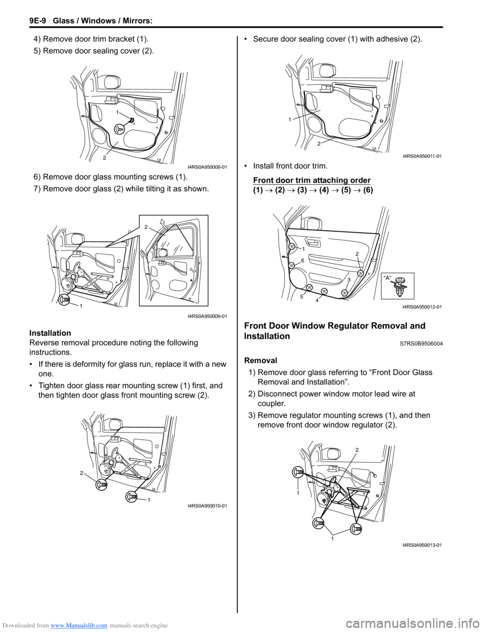
4) Remove door trim bracket (1).
5) Remove door sealing cover (2).
6) Remove door glass mounting screws (1).
7) Remove door glass (2) while tilting it as shown.
Installation
Reverse removal procedure noting the following
instructions.
• If there is deformity for glass run, replace it with a new one.
• Tighten door glass rear mounting screw (1) first, and then tighten door glass front mounting screw (2). • Secure door sealing cover (1) with adhesive (2).
• Install front door trim.
Front door trim attaching order
(1) → (2) → (3) → (4) → (5) → (6)
Front Door Window Regulator Removal and
Installation
S7RS0B9506004
Removal
1) Remove door glass referring to “Front Door Glass Removal and Installation”.
2) Disconnect power window motor lead wire at coupler.
3) Remove regulator mounting screws (1), and then remove front door window regulator (2).
1
2
I4RS0A950008-01
2
1
I4RS0A950009-01
1
2
I4RS0A950010-01
2
1
I4RS0A950011-01
“A”“A”
“A”
“A”
“A”“A”“A”
1 2
3
4
5 6
I4RS0A950012-01
1
1
2
I4RS0A950013-01
Page 1337 of 1496
Downloaded from www.Manualslib.com manuals search engine Glass / Windows / Mirrors: 9E-10
Installation
Reverse removal procedure noting the following
instruction.
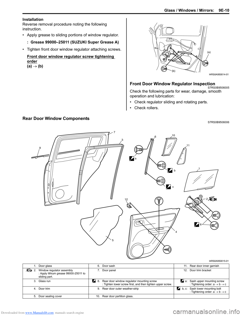
• Apply grease to sliding portions of window regulator.: Grease 99000–25011 (SUZUKI Super Grease A)
• Tighten front door window regulator attaching screws. Front door window regulator screw tightening
order
(a) → (b)
Front Door Window Regulator InspectionS7RS0B9506005
Check the following parts for wear, dama ge, smooth
operation and lubrication:
• Check regulator sliding and rotating parts.
• Check rollers.
Rear Door Window ComponentsS7RS0B9506006
(a)
(b)
I4RS0A950014-01
9
7
3610
11
b
c
12
5 2
8
4
a
1
I4RS0A950015-01
1. Door glass
6. Door sash 11. Rear door inner garnish
2. Window regulator assembly : Apply lithium grease 99000-25011 to
sliding part. 7. Door panel
12. Door trim bracket
3. Glass run 8. Rear door window regulator mounting screw
: Tighten lower screw first, and then tighten upper screw. a: Sash upper mounting screw
: Tightening order: a → b → c
4. Door trim 9. Rear door outer weather-strip b, c: Sash lower mounting bolt
: Tightening order: a → b → c
5. Door sealing cover 10. Rear door partition glass.
Page 1338 of 1496
Downloaded from www.Manualslib.com manuals search engine 9E-11 Glass / Windows / Mirrors:
Rear Door Glass Removal and InstallationS7RS0B9506007
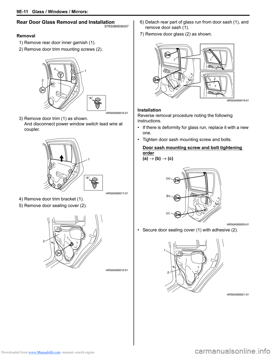
Removal1) Remove rear door inner garnish (1).
2) Remove door trim mounting screws (2).
3) Remove door trim (1) as shown. And disconnect power wi ndow switch lead wire at
coupler.
4) Remove door trim bracket (1).
5) Remove door sealing cover (2). 6) Detach rear part of glass run from door sash (1), and
remove door sash (1).
7) Remove door glass (2) as shown.
Installation
Reverse removal procedure noting the following
instructions.
• If there is deformity for glass run, replace it with a new one.
• Tighten door sash mounting screw and bolts.
Door sash mounting screw and bolt tightening
order
(a) → (b) → (c)
• Secure door sealing cover (1) with adhesive (2).
“A”
“A”
“A”
2
2 1
I4RS0A950016-01
“A”
“A”
“A”
“A”“A”
“A”
“A”
1
I4RS0A950017-01
1
2
I4RS0A950018-01
1
1
2
I4RS0A950019-01
(a)
(b)
(c)
I4RS0A950020-01
1
2
I4RS0A950021-01
Page 1365 of 1496
Downloaded from www.Manualslib.com manuals search engine Seats: 9G-3
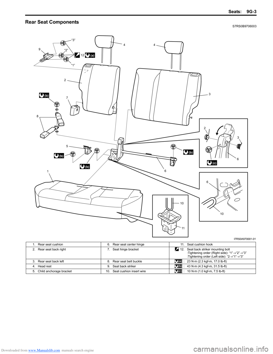
Rear Seat ComponentsS7RS0B9706003
1
5
(b)
(b)
(b)
8
7
9
2
4
4
3
(b)
6
6(c)
2
3
10
6
(a)
10
11
12
“1”
“2”
“3”
I7RS0A970001-01
1. Rear seat cushion
6. Rear seat center hinge11. Seat cushion hook
2. Rear seat back right 7. Seat hinge bracket12. Seat back striker mounting bolt
:Tightening order (Right side): “1” →“2” →“3”
:Tightening order (Left side): “2 →“1” →“3”
3. Rear seat back left 8. Rear seat belt buckle : 23 N⋅m (2.3 kgf-m, 17.0 lb-ft)
4. Head rest 9. Seat back striker : 43 N⋅m (4.3 kgf-m, 31.5 lb-ft)
5. Child anchorage bracket 10. Seat cushion insert wire : 10 N⋅m (1.0 kgf-m, 7.5 lb-ft)
Page 1366 of 1496
Downloaded from www.Manualslib.com manuals search engine 9G-4 Seats:
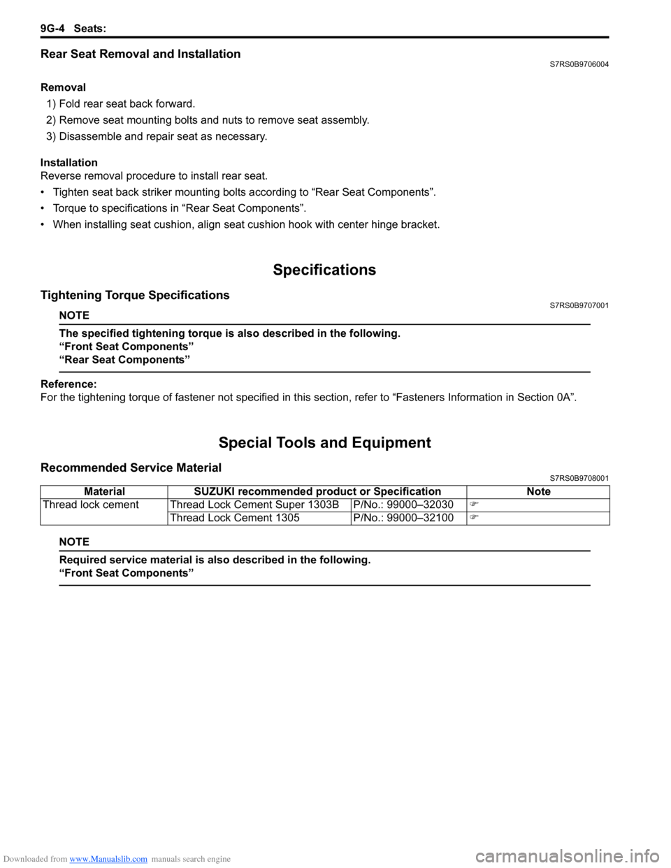
Rear Seat Removal and InstallationS7RS0B9706004
Removal1) Fold rear seat back forward.
2) Remove seat mounting bolts and nuts to remove seat assembly.
3) Disassemble and repair seat as necessary.
Installation
Reverse removal procedure to install rear seat.
• Tighten seat back striker mounting bolts according to “Rear Seat Components”.
• Torque to specifications in “Rear Seat Components”.
• When installing seat cushion, align seat cushion hook with center hinge bracket.
Specifications
Tightening Torque SpecificationsS7RS0B9707001
NOTE
The specified tightening torque is also described in the following.
“Front Seat Components”
“Rear Seat Components”
Reference:
For the tightening torque of fastener not specified in this section, refer to “Fasteners Information in Section 0A”.
Special Tools and Equipment
Recommended Service MaterialS7RS0B9708001
NOTE
Required service material is also described in the following.
“Front Seat Components”
Material SUZUKI recommended product or Specification Note
Thread lock cement Thread Lock Cement Super 1303B P/No.: 99000–32030 )
Thread Lock Cement 1305 P/No.: 99000–32100 )