shift lock SUZUKI SWIFT 2007 2.G Service Service Manual
[x] Cancel search | Manufacturer: SUZUKI, Model Year: 2007, Model line: SWIFT, Model: SUZUKI SWIFT 2007 2.GPages: 1496, PDF Size: 34.44 MB
Page 783 of 1496
Downloaded from www.Manualslib.com manuals search engine Automatic Transmission/Transaxle: 5A-139
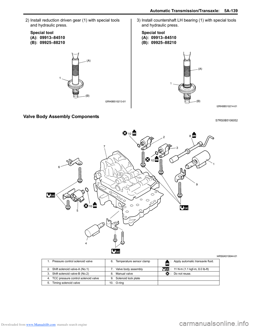
2) Install reduction driven gear (1) with special tools and hydraulic press.
Special tool
(A): 09913–84510
(B): 09925–88210 3) Install countershaft LH bearing (1) with special tools
and hydraulic press.
Special tool
(A): 09913–84510
(B): 09925–88210
Valve Body Assembly ComponentsS7RS0B5106052
I2RH0B510213-01
I2RH0B510214-01
I4RS0A510044-01
1. Pressure control solenoid valve 6. Temperature sensor clamp : Apply automatic transaxle fluid.
2. Shift solenoid valve-A (No.1) 7. Valve body assembly: 11 N⋅m (1.1 kgf-m, 8.0 lb-ft)
3. Shift solenoid valve-B (No.2) 8. Manual valve: Do not reuse.
4. TCC pressure control solenoid valve 9. Solenoid lock plate
5. Timing solenoid valve 10. O-ring
Page 784 of 1496
Downloaded from www.Manualslib.com manuals search engine 5A-140 Automatic Transmission/Transaxle:
Valve Body Assembly Disassembly and
Reassembly
S7RS0B5106053
CAUTION!
When replacing pressure control solenoid
valve and/or TCC pressure control solenoid
valve, it is strictly required to replace it
together with valve body assembly as a set.
Replacing pressure control solenoid valve
and/or TCC pressure control solenoid valve
independently may cause excessive shift
shock.
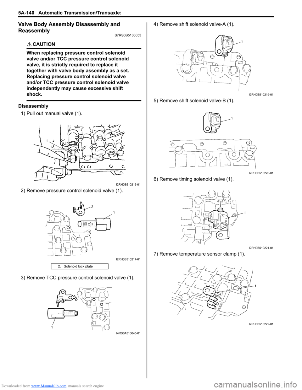
Disassembly1) Pull out manual valve (1).
2) Remove pressure cont rol solenoid valve (1).
3) Remove TCC pressure control solenoid valve (1). 4) Remove shift solenoid valve-A (1).
5) Remove shift solenoid valve-B (1).
6) Remove timing solenoid valve (1).
7) Remove temperature sensor clamp (1).
2. Solenoid lock plate
I2RH0B510216-01
I2RH0B510217-01
1
I4RS0A510045-01
I2RH0B510219-01
I2RH0B510220-01
I2RH0B510221-01
I2RH0B510222-01
Page 794 of 1496
Downloaded from www.Manualslib.com manuals search engine 5A-150 Automatic Transmission/Transaxle:
Automatic Transaxle Unit AssemblyS7RS0B5106060
CAUTION!
• Automatic transaxle consists of highly precise parts. As even flaw in small part
may cause oil leakage or decrease in
function, check each part carefully before
installation.
• Clean all parts with compressed air. Never use wiping cloths or rags.
• Before assembling new clutch or brake discs, soak them in automatic transaxle
fluid for at least 2 hours.
• Be sure to use new gaskets and O-rings.
• Lubricate O-rings with automatic transaxle
fluid.
• Apply automatic transaxle fluid on sliding or rotating surfaces of the parts before
assembly.
• Use Suzuki Super Grease “C” to retain parts in place.
• Be sure to install thrust bearings and races in correct direction and position.
• Make sure that snap ring ends are not aligned with one of cut outs and are
installed in groove correctly.
• Do not use adhesive cements on gaskets and similar parts.
• Be sure to torque each bolt and nut to specification.
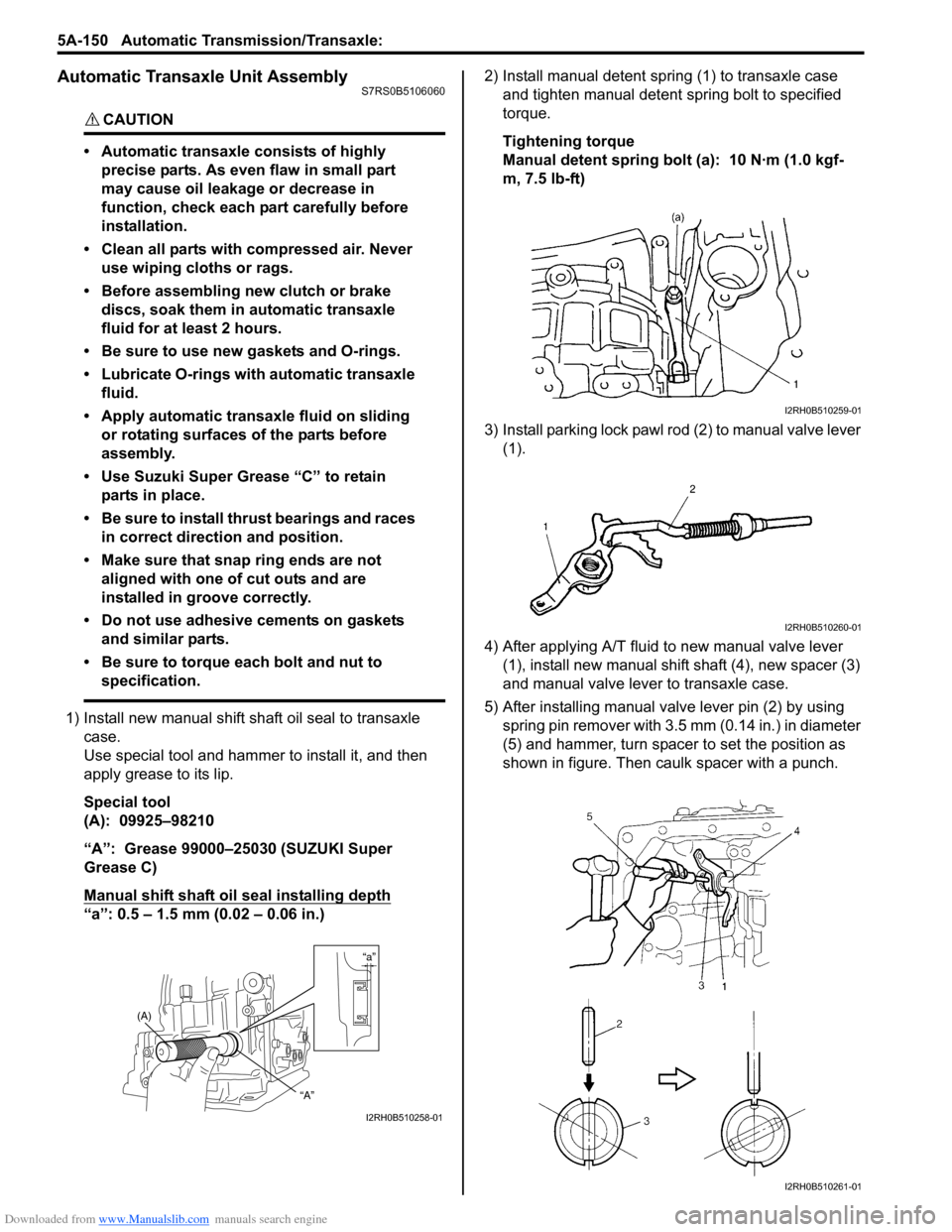
1) Install new manual shift sh aft oil seal to transaxle
case.
Use special tool and hammer to install it, and then
apply grease to its lip.
Special tool
(A): 09925–98210
“A”: Grease 99000–25030 (SUZUKI Super
Grease C)
Manual shift shaft oil seal installing depth
“a”: 0.5 – 1.5 mm (0.02 – 0.06 in.) 2) Install manual detent spring (1) to transaxle case
and tighten manual detent spring bolt to specified
torque.
Tightening torque
Manual detent spring bolt (a): 10 N·m (1.0 kgf-
m, 7.5 lb-ft)
3) Install parking lock pawl ro d (2) to manual valve lever
(1).
4) After applying A/T fluid to new manual valve lever (1), install new manual shift shaft (4), new spacer (3)
and manual valve lever to transaxle case.
5) After installing manual valve lever pin (2) by using spring pin remover with 3.5 mm (0.14 in.) in diameter
(5) and hammer, turn spacer to set the position as
shown in figure. Then caulk spacer with a punch.
“a”
(A)
“A”
I2RH0B510258-01
I2RH0B510259-01
I2RH0B510260-01
I2RH0B510261-01
Page 809 of 1496
Downloaded from www.Manualslib.com manuals search engine Automatic Transmission/Transaxle: 5A-165
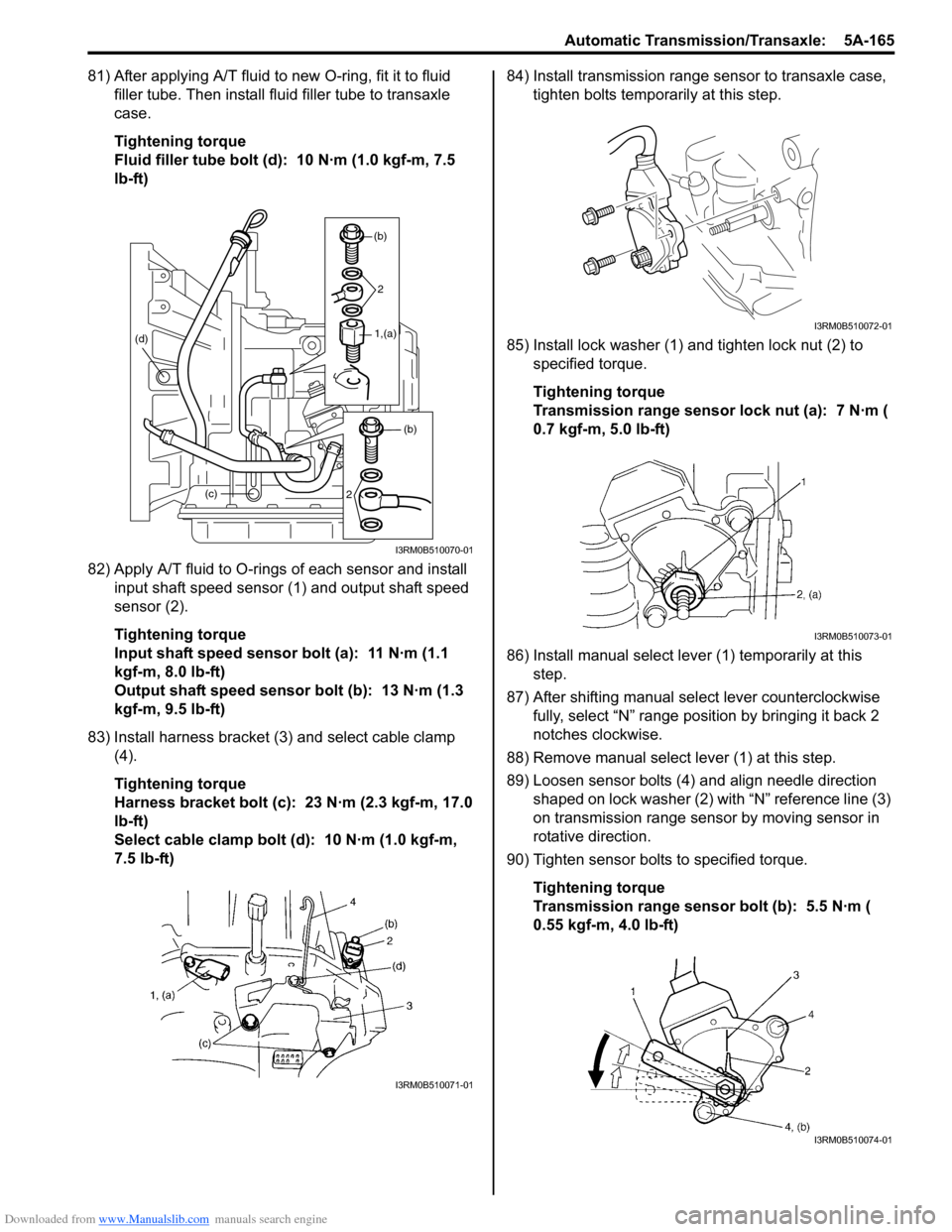
81) After applying A/T fluid to new O-ring, fit it to fluid filler tube. Then install fl uid filler tube to transaxle
case.
Tightening torque
Fluid filler tube bolt (d): 10 N·m (1.0 kgf-m, 7.5
lb-ft)
82) Apply A/T fluid to O-rings of each sensor and install input shaft speed sensor (1) and output shaft speed
sensor (2).
Tightening torque
Input shaft speed sensor bolt (a): 11 N·m (1.1
kgf-m, 8.0 lb-ft)
Output shaft speed sensor bolt (b): 13 N·m (1.3
kgf-m, 9.5 lb-ft)
83) Install harness bracket (3) and select cable clamp (4).
Tightening torque
Harness bracket bolt (c): 23 N·m (2.3 kgf-m, 17.0
lb-ft)
Select cable clamp bolt (d): 10 N·m (1.0 kgf-m,
7.5 lb-ft) 84) Install transmission range sensor to transaxle case,
tighten bolts temporarily at this step.
85) Install lock washer (1) and tighten lock nut (2) to specified torque.
Tightening torque
Transmission range sensor lock nut (a): 7 N·m (
0.7 kgf-m, 5.0 lb-ft)
86) Install manual select leve r (1) temporarily at this
step.
87) After shifting manual se lect lever counterclockwise
fully, select “N” range position by bringing it back 2
notches clockwise.
88) Remove manual select lever (1) at this step.
89) Loosen sensor bolts (4) and align needle direction shaped on lock washer (2) with “N” reference line (3)
on transmission range sensor by moving sensor in
rotative direction.
90) Tighten sensor bolts to specified torque.
Tightening torque
Transmission range sensor bolt (b): 5.5 N·m (
0.55 kgf-m, 4.0 lb-ft)
(c)
(d)
(b)
2
1,(a)
(b)
2
I3RM0B510070-01
I3RM0B510071-01
I3RM0B510072-01
I3RM0B510073-01
I3RM0B510074-01
Page 811 of 1496

Downloaded from www.Manualslib.com manuals search engine Automatic Transmission/Transaxle: 5A-167
Specifications
Tightening Torque SpecificationsS7RS0B5107001
NOTE
The specified tightening torque is also described in the following.
“Select Cable Components”
“Automatic Transaxle Unit Components”
“Automatic Transaxle Assembly Components”
“Oil Pump Assembly Components”
“Transaxle Rear Cover (O/D and 2nd Coast Brake Piston) Assembly Components”
“Valve Body Assembly Components”
“Differential Assembly Components”
Reference:
For the tightening torque of fastener not specified in this section, refer to “Fasteners Information in Section 0A”.
Fastening part
Tightening torque
Note
N ⋅mkgf-mlb-ft
A/T fluid drain plug 171.7 12.5 �) / �) / �)
Transmission range sensor bolt 5.5 0.55 4.0�) / �)
Output shaft speed sensor bolt 131.3 9.5 �) / �)
Input shaft speed sensor bolt 5.5 0.55 4.0�)
Valve body harness connector bolt 7.00.7 5.0 �)
Shift solenoid bolt 111.1 8.0 �)
Oil strainer bolt 101.0 7.5 �) / �)
Oil pan bolt 7.00.7 5.0 �) / �)
Transaxle and engine fastening bolt and nut 85 8.5 61.5�)
Drive plate to torque converter bolt 252.5 18.0 �)
Transaxle stiffener bolt 555.5 40�)
Starter motor bolt and nut 505.0 36.5 �)
Oil pump subassembly bolt 101.0 7.5 �)
Rear cover plug 7.5 0.75 5.5�)
Solenoid valve bolt 111.1 8.0 �)
Final gear bolt 787.8 56.5 �)
Torque converter housing plug 7.5 0.75 5.5�)
Lubrication tube clamp bolt 5.5 0.55 4.0�)
Fluid reservoir RH plate bolt 5.5 0.55 4.0�)
Torque converter housing bolt 292.9 21�) / �) / �)
Manual detent spring bolt 101.0 7.5 �)
Parking lock pawl bracket bolt 7.5 0.75 5.5�)
Rear cover bolt 252.5 18.0 �)
Fluid reservoir LH plate bolt 101.0 7.5 �)
Oil pump assembly bolt 252.5 18.0 �)
Transaxle case plug 7.5 0.75 5.5�)
Valve body harness connector bolt 5.5 0.55 4.0�)
Valve body bolt 111.1 8.0 �)
Fluid outlet union 252.5 18.0 �)
Fluid cooler pipe union bolt 222.2 16.0 �)
Fluid cooler pipe bracket bolt 101.0 7.5 �)
Fluid filler tube bolt 101.0 7.5 �)
Input shaft speed sensor bolt 111.1 8.0 �)
Harness bracket bolt 232.3 17.0 �)
Select cable clamp bolt 101.0 7.5 �)
Transmission range sensor lock nut 70.7 5.0 �)
Manual select lever nut 131.3 9.5 �)
Engine mounting LH bracket bolt 555.5 40.0
�)
Page 820 of 1496
Downloaded from www.Manualslib.com manuals search engine 5B-6 Manual Transmission/Transaxle:
Gear Shift Control Lever and Cable Removal
and Installation
S7RS0B5206004
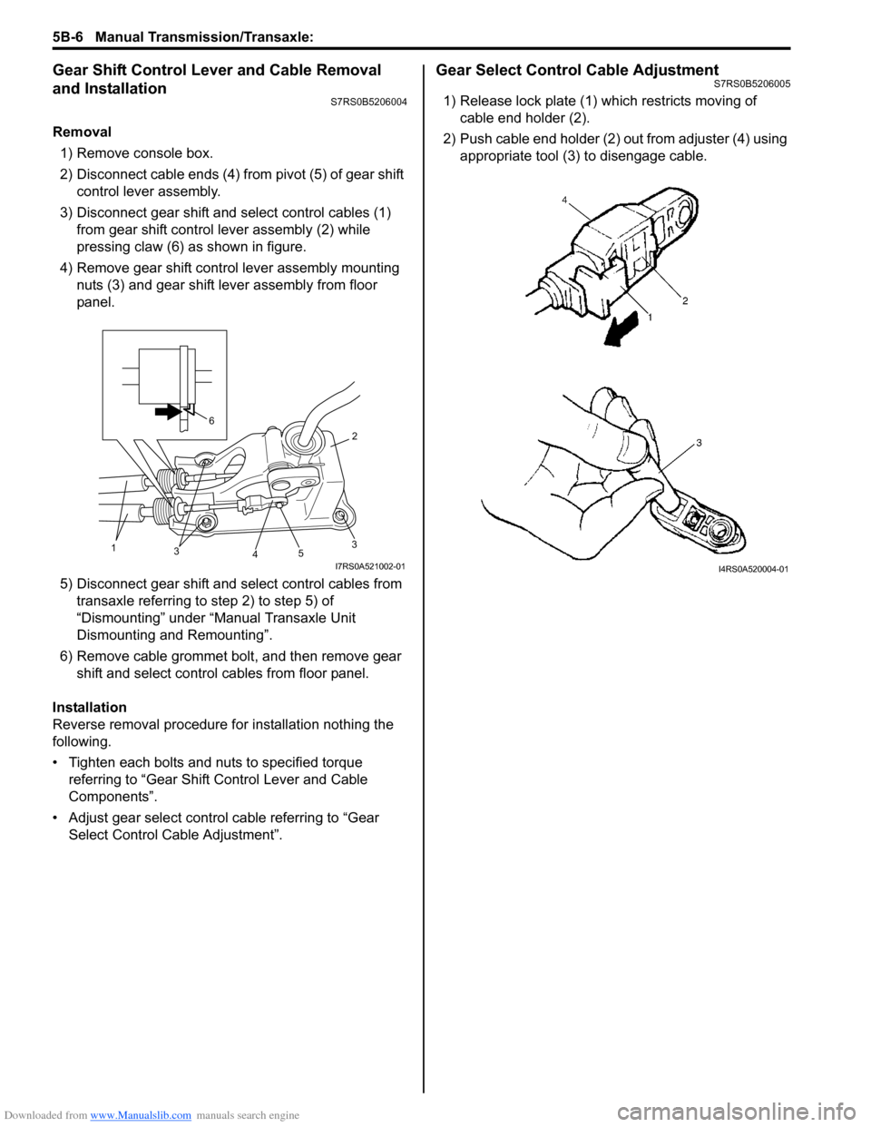
Removal1) Remove console box.
2) Disconnect cable ends (4) from pivot (5) of gear shift control lever assembly.
3) Disconnect gear shift and select control cables (1) from gear shift control lever assembly (2) while
pressing claw (6) as shown in figure.
4) Remove gear shift control lever assembly mounting nuts (3) and gear shift lever assembly from floor
panel.
5) Disconnect gear shift and select control cables from transaxle referring to step 2) to step 5) of
“Dismounting” under “Manual Transaxle Unit
Dismounting and Remounting”.
6) Remove cable grommet bolt, and then remove gear shift and select control cables from floor panel.
Installation
Reverse removal procedure for installation nothing the
following.
• Tighten each bolts and nuts to specified torque referring to “Gear Shift Control Lever and Cable
Components”.
• Adjust gear select control cable referring to “Gear Select Control Cable Adjustment”.
Gear Select Control Cable AdjustmentS7RS0B5206005
1) Release lock plate (1) which restricts moving of cable end holder (2).
2) Push cable end holder (2) out from adjuster (4) using appropriate tool (3) to disengage cable.
35
4
2
31
6
I7RS0A521002-01I4RS0A520004-01
Page 821 of 1496
Downloaded from www.Manualslib.com manuals search engine Manual Transmission/Transaxle: 5B-7
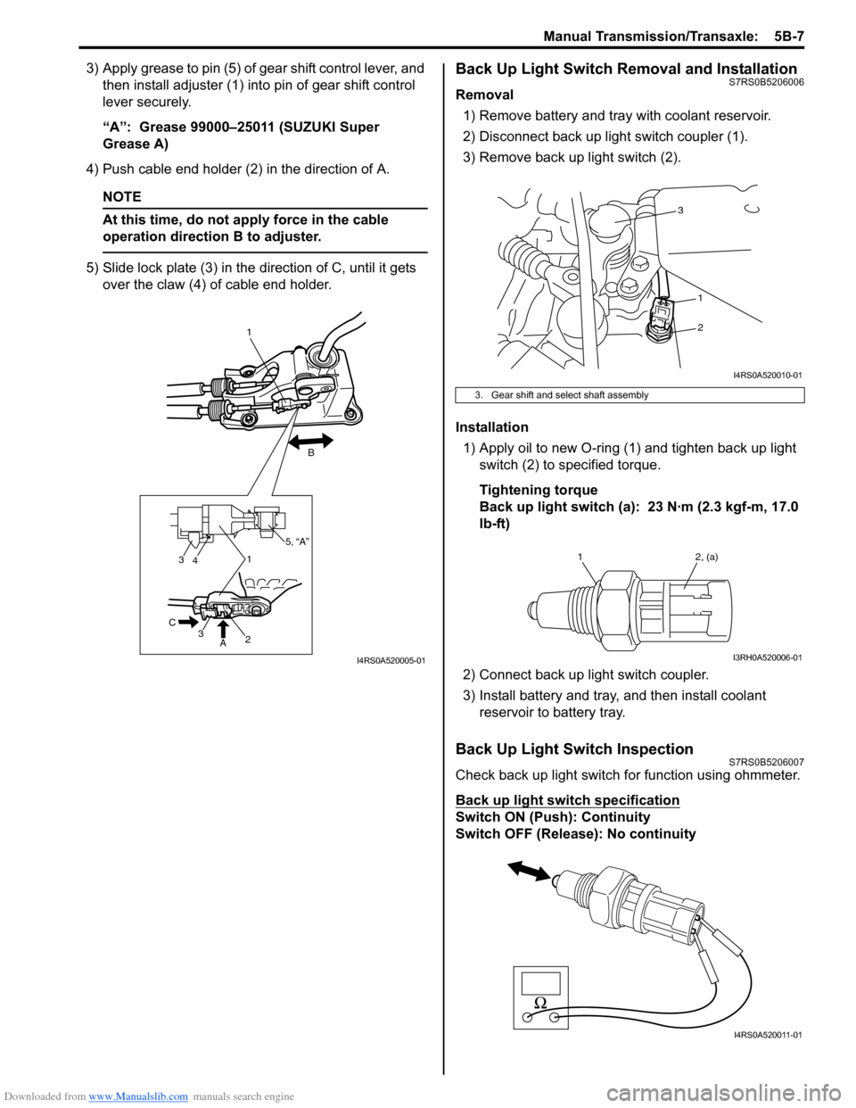
3) Apply grease to pin (5) of gear shift control lever, and then install adjuster (1) into pin of gear shift control
lever securely.
“A”: Grease 99000–25011 (SUZUKI Super
Grease A)
4) Push cable end holder (2) in the direction of A.
NOTE
At this time, do not a pply force in the cable
operation direction B to adjuster.
5) Slide lock plate (3) in the direction of C, until it gets over the claw (4) of cable end holder.
Back Up Light Switch Removal and InstallationS7RS0B5206006
Removal
1) Remove battery and tray with coolant reservoir.
2) Disconnect back up light switch coupler (1).
3) Remove back up light switch (2).
Installation 1) Apply oil to new O-ring (1) and tighten back up light switch (2) to specified torque.
Tightening torque
Back up light switch (a): 23 N·m (2.3 kgf-m, 17.0
lb-ft)
2) Connect back up light switch coupler.
3) Install battery and tray, and then install coolant reservoir to battery tray.
Back Up Light Switch InspectionS7RS0B5206007
Check back up light switch for function using ohmmeter.
Back up light switch specification
Switch ON (Push): Continuity
Switch OFF (Release ): No continuity
3
3
41
2
A
C
1
B
5, “A”
I4RS0A520005-01
3. Gear shift and select shaft assembly
3
1
2
I4RS0A520010-01
1 2, (a)
I3RH0A520006-01
I4RS0A520011-01
Page 825 of 1496
Downloaded from www.Manualslib.com manuals search engine Manual Transmission/Transaxle: 5B-11
Gear Shift and Select Shaft Assembly ComponentsS7RS0B5206010
Gear Shift and Select Shaft Assembly Removal
and Installation
S7RS0B5206011
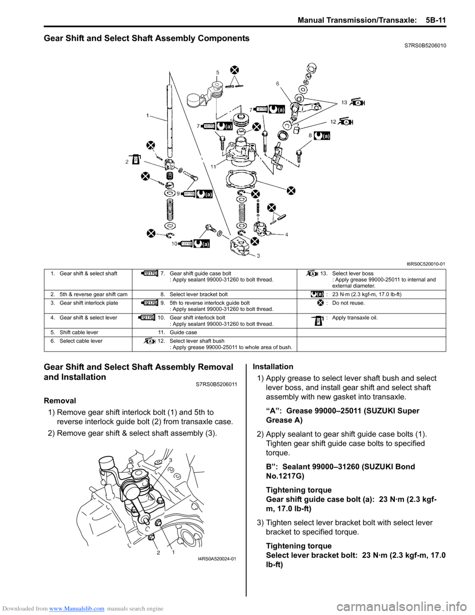
Removal1) Remove gear shift interlock bolt (1) and 5th to reverse interlock guide bolt (2) from transaxle case.
2) Remove gear shift & select shaft assembly (3). Installation
1) Apply grease to select lever shaft bush and select lever boss, and install gear shift and select shaft
assembly with new gasket into transaxle.
“A”: Grease 99000–25011 (SUZUKI Super
Grease A)
2) Apply sealant to gear shift guide case bolts (1). Tighten gear shift guide case bolts to specified
torque.
B”: Sealant 99000–31260 (SUZUKI Bond
No.1217G)
Tightening torque
Gear shift guide case bolt (a): 23 N·m (2.3 kgf-
m, 17.0 lb-ft)
3) Tighten select lever brac ket bolt with select lever
bracket to specified torque.
Tightening torque
Select lever bracket bolt: 23 N·m (2.3 kgf-m, 17.0
lb-ft)
I6RS0C520010-01
1. Gear shift & select shaft 7. Gear shift guide case bolt
: Apply sealant 99000-31260 to bolt thread. 13. Select lever boss
: Apply grease 99000-25011 to internal and
external diameter.
2. 5th & reverse gear shift cam 8. Select lever bracket bolt : 23 N⋅m (2.3 kgf-m, 17.0 lb-ft)
3. Gear shift interlock plate 9. 5th to reverse interlock guide bolt
: Apply sealant 99000-31260 to bolt thread. : Do not reuse.
4. Gear shift & select lever 10. Gear shift interlock bolt
: Apply sealant 99000-31260 to bolt thread. : Apply transaxle oil.
5. Shift cable lever 11. Guide case
6. Select cable lever 12. Select lever shaft bush
: Apply grease 99000-25011 to whole area of bush.
3
12I4RS0A520024-01
Page 826 of 1496
Downloaded from www.Manualslib.com manuals search engine 5B-12 Manual Transmission/Transaxle:
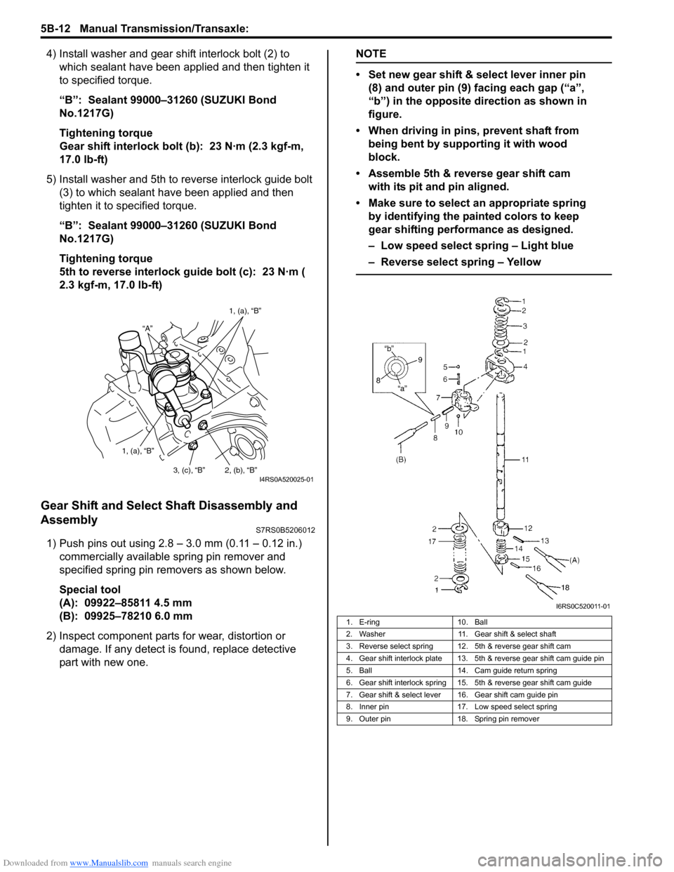
4) Install washer and gear shift interlock bolt (2) to which sealant have been app lied and then tighten it
to specified torque.
“B”: Sealant 99000–31260 (SUZUKI Bond
No.1217G)
Tightening torque
Gear shift interlock bolt (b): 23 N·m (2.3 kgf-m,
17.0 lb-ft)
5) Install washer and 5th to reverse interlock guide bolt (3) to which sealant have been applied and then
tighten it to specified torque.
“B”: Sealant 99000–31260 (SUZUKI Bond
No.1217G)
Tightening torque
5th to reverse interlock guide bolt (c): 23 N·m (
2.3 kgf-m, 17.0 lb-ft)
Gear Shift and Select Shaft Disassembly and
Assembly
S7RS0B5206012
1) Push pins out using 2.8 – 3.0 mm (0.11 – 0.12 in.) commercially available spring pin remover and
specified spring pin removers as shown below.
Special tool
(A): 09922–85811 4.5 mm
(B): 09925–78210 6.0 mm
2) Inspect component parts for wear, distortion or
damage. If any detect is found, replace detective
part with new one.
NOTE
• Set new gear shift & select lever inner pin (8) and outer pin (9) facing each gap (“a”,
“b”) in the opposite direction as shown in
figure.
• When driving in pins, prevent shaft from being bent by supporting it with wood
block.
• Assemble 5th & reverse gear shift cam with its pit and pin aligned.
• Make sure to select an appropriate spring by identifying the painted colors to keep
gear shifting performance as designed.
– Low speed select spring – Light blue
– Reverse select spring – Yellow
“A” 1, (a), “B”
1, (a), “B” 2, (b), “B”
3, (c), “B”
I4RS0A520025-01
1. E-ring 10. Ball
2. Washer 11. Gear shift & select shaft
3. Reverse select spring 12. 5th & reverse gear shift cam
4. Gear shift interlock plate 13. 5th & reverse gear shift cam guide pin
5. Ball 14. Cam guide return spring
6. Gear shift interlock spring 15. 5th & reverse gear shift cam guide
7. Gear shift & select lever 16. Gear shift cam guide pin
8. Inner pin 17. Low speed select spring
9. Outer pin 18. Spring pin remover
I6RS0C520011-01
Page 827 of 1496
Downloaded from www.Manualslib.com manuals search engine Manual Transmission/Transaxle: 5B-13
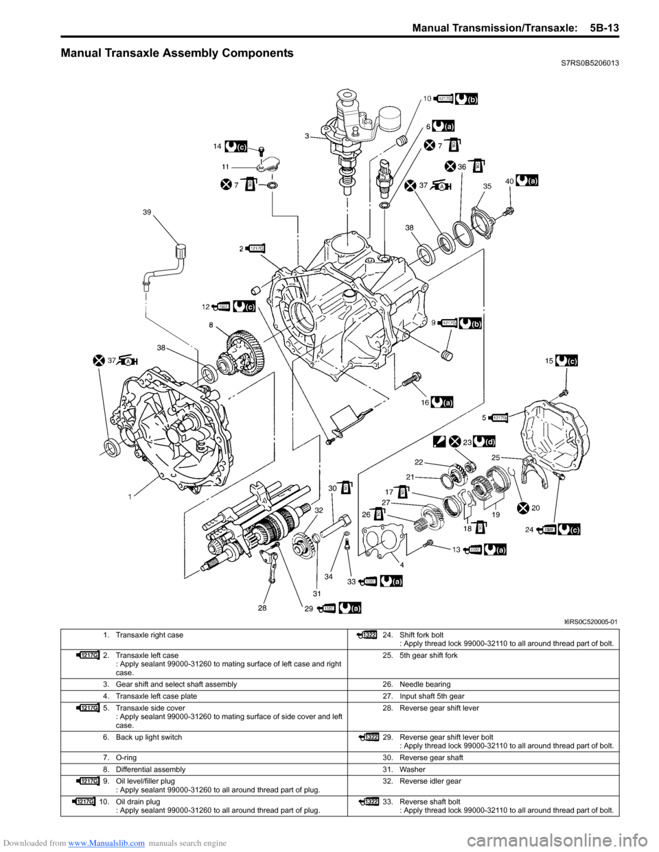
Manual Transaxle Assembly ComponentsS7RS0B5206013
I6RS0C520005-01
1. Transaxle right case 24. Shift fork bolt
: Apply thread lock 99000-32110 to all around thread part of bolt.
2. Transaxle left case : Apply sealant 99000-31260 to mating surface of left case and right
case. 25. 5th gear shift fork
3. Gear shift and select shaft assembly 26. Needle bearing
4. Transaxle left case plate 27. Input shaft 5th gear
5. Transaxle side cover : Apply sealant 99000-31260 to mating surface of side cover and left
case. 28. Reverse gear shift lever
6. Back up light switch 29. Reverse gear shift lever bolt
: Apply thread lock 99000-32110 to all around thread part of bolt.
7. O-ring 30. Reverse gear shaft
8. Differential assembly 31. Washer
9. Oil level/filler plug : Apply sealant 99000-31260 to all around thread part of plug. 32. Reverse idler gear
10. Oil drain plug : Apply sealant 99000-31260 to all around thread part of plug. 33. Reverse shaft bolt
: Apply thread lock 99000-32110 to all around thread part of bolt.